EP0049154B2 - Nettoyage de diffuseurs in situ utilisant du gaz - Google Patents
Nettoyage de diffuseurs in situ utilisant du gaz Download PDFInfo
- Publication number
- EP0049154B2 EP0049154B2 EP19810304493 EP81304493A EP0049154B2 EP 0049154 B2 EP0049154 B2 EP 0049154B2 EP 19810304493 EP19810304493 EP 19810304493 EP 81304493 A EP81304493 A EP 81304493A EP 0049154 B2 EP0049154 B2 EP 0049154B2
- Authority
- EP
- European Patent Office
- Prior art keywords
- elements
- pressure
- cleaning
- gas
- diffusion
- Prior art date
- Legal status (The legal status is an assumption and is not a legal conclusion. Google has not performed a legal analysis and makes no representation as to the accuracy of the status listed.)
- Expired - Lifetime
Links
- 238000009792 diffusion process Methods 0.000 title claims description 321
- 238000004140 cleaning Methods 0.000 title claims description 308
- 239000007789 gas Substances 0.000 claims description 451
- 238000000034 method Methods 0.000 claims description 117
- 239000007788 liquid Substances 0.000 claims description 104
- XLYOFNOQVPJJNP-UHFFFAOYSA-N water Substances O XLYOFNOQVPJJNP-UHFFFAOYSA-N 0.000 claims description 93
- 239000011148 porous material Substances 0.000 claims description 75
- 239000012530 fluid Substances 0.000 claims description 69
- 230000008569 process Effects 0.000 claims description 63
- 230000006835 compression Effects 0.000 claims description 57
- 238000007906 compression Methods 0.000 claims description 57
- 239000000463 material Substances 0.000 claims description 55
- 238000005273 aeration Methods 0.000 claims description 47
- 230000002093 peripheral effect Effects 0.000 claims description 46
- 238000009826 distribution Methods 0.000 claims description 41
- 239000000203 mixture Substances 0.000 claims description 39
- 230000009467 reduction Effects 0.000 claims description 37
- 230000001105 regulatory effect Effects 0.000 claims description 30
- 239000010865 sewage Substances 0.000 claims description 24
- 230000001965 increasing effect Effects 0.000 claims description 21
- 239000000919 ceramic Substances 0.000 claims description 19
- 230000002706 hydrostatic effect Effects 0.000 claims description 18
- QVGXLLKOCUKJST-UHFFFAOYSA-N atomic oxygen Chemical compound [O] QVGXLLKOCUKJST-UHFFFAOYSA-N 0.000 claims description 17
- 239000001301 oxygen Substances 0.000 claims description 17
- 229910052760 oxygen Inorganic materials 0.000 claims description 17
- 230000002829 reductive effect Effects 0.000 claims description 16
- 230000004907 flux Effects 0.000 claims description 10
- 238000009530 blood pressure measurement Methods 0.000 claims description 9
- 238000004891 communication Methods 0.000 claims description 9
- 230000008859 change Effects 0.000 claims description 8
- 230000001276 controlling effect Effects 0.000 claims description 6
- VNWKTOKETHGBQD-UHFFFAOYSA-N methane Natural products C VNWKTOKETHGBQD-UHFFFAOYSA-N 0.000 claims description 6
- 229920006395 saturated elastomer Polymers 0.000 claims description 6
- 239000007864 aqueous solution Substances 0.000 claims description 5
- 230000008021 deposition Effects 0.000 claims description 5
- 238000007599 discharging Methods 0.000 claims description 5
- 230000000977 initiatory effect Effects 0.000 claims description 5
- 150000001875 compounds Chemical class 0.000 claims description 4
- 239000004094 surface-active agent Substances 0.000 claims description 4
- OKKJLVBELUTLKV-UHFFFAOYSA-N Methanol Chemical compound OC OKKJLVBELUTLKV-UHFFFAOYSA-N 0.000 claims description 2
- 239000003929 acidic solution Substances 0.000 claims description 2
- OSVXSBDYLRYLIG-UHFFFAOYSA-N chlorine dioxide Inorganic materials O=Cl=O OSVXSBDYLRYLIG-UHFFFAOYSA-N 0.000 claims description 2
- 235000019398 chlorine dioxide Nutrition 0.000 claims description 2
- QBWCMBCROVPCKQ-UHFFFAOYSA-N chlorous acid Chemical compound OCl=O QBWCMBCROVPCKQ-UHFFFAOYSA-N 0.000 claims description 2
- 230000003247 decreasing effect Effects 0.000 claims description 2
- 239000010842 industrial wastewater Substances 0.000 claims description 2
- 238000012544 monitoring process Methods 0.000 claims 2
- 239000002574 poison Substances 0.000 claims 1
- 231100000614 poison Toxicity 0.000 claims 1
- 239000002245 particle Substances 0.000 description 43
- 238000007789 sealing Methods 0.000 description 43
- 230000035699 permeability Effects 0.000 description 36
- 238000012360 testing method Methods 0.000 description 31
- VEXZGXHMUGYJMC-UHFFFAOYSA-N Hydrochloric acid Chemical compound Cl VEXZGXHMUGYJMC-UHFFFAOYSA-N 0.000 description 25
- CURLTUGMZLYLDI-UHFFFAOYSA-N Carbon dioxide Chemical compound O=C=O CURLTUGMZLYLDI-UHFFFAOYSA-N 0.000 description 24
- IXCSERBJSXMMFS-UHFFFAOYSA-N hydrogen chloride Substances Cl.Cl IXCSERBJSXMMFS-UHFFFAOYSA-N 0.000 description 23
- 229910000041 hydrogen chloride Inorganic materials 0.000 description 23
- 238000003825 pressing Methods 0.000 description 22
- 230000000694 effects Effects 0.000 description 20
- 239000007787 solid Substances 0.000 description 15
- 230000008901 benefit Effects 0.000 description 12
- 229910002092 carbon dioxide Inorganic materials 0.000 description 12
- 230000007423 decrease Effects 0.000 description 12
- 238000000576 coating method Methods 0.000 description 11
- 239000000523 sample Substances 0.000 description 11
- KZBUYRJDOAKODT-UHFFFAOYSA-N Chlorine Chemical compound ClCl KZBUYRJDOAKODT-UHFFFAOYSA-N 0.000 description 10
- 239000000243 solution Substances 0.000 description 10
- 230000001464 adherent effect Effects 0.000 description 9
- 230000009286 beneficial effect Effects 0.000 description 9
- 230000015572 biosynthetic process Effects 0.000 description 9
- 239000011236 particulate material Substances 0.000 description 9
- 239000011248 coating agent Substances 0.000 description 8
- 238000001802 infusion Methods 0.000 description 8
- 238000004519 manufacturing process Methods 0.000 description 8
- 239000004033 plastic Substances 0.000 description 8
- 229920003023 plastic Polymers 0.000 description 8
- 239000010802 sludge Substances 0.000 description 8
- 239000002253 acid Substances 0.000 description 7
- 230000008093 supporting effect Effects 0.000 description 7
- ZAMOUSCENKQFHK-UHFFFAOYSA-N Chlorine atom Chemical compound [Cl] ZAMOUSCENKQFHK-UHFFFAOYSA-N 0.000 description 6
- 241000405070 Percophidae Species 0.000 description 6
- VYPSYNLAJGMNEJ-UHFFFAOYSA-N Silicium dioxide Chemical compound O=[Si]=O VYPSYNLAJGMNEJ-UHFFFAOYSA-N 0.000 description 6
- 239000000460 chlorine Substances 0.000 description 6
- 229910052801 chlorine Inorganic materials 0.000 description 6
- 238000013461 design Methods 0.000 description 6
- 238000012986 modification Methods 0.000 description 6
- 230000004048 modification Effects 0.000 description 6
- SVKQEADHBGJMJB-FHLIZLRMSA-N ram-317 Chemical compound C1CCC[C@@]2(O)[C@H]3CC4=CC=C(OC)C(O)=C4[C@]21CCN3C SVKQEADHBGJMJB-FHLIZLRMSA-N 0.000 description 6
- PNEYBMLMFCGWSK-UHFFFAOYSA-N aluminium oxide Inorganic materials [O-2].[O-2].[O-2].[Al+3].[Al+3] PNEYBMLMFCGWSK-UHFFFAOYSA-N 0.000 description 5
- 230000008878 coupling Effects 0.000 description 5
- 238000010168 coupling process Methods 0.000 description 5
- 238000005859 coupling reaction Methods 0.000 description 5
- 238000002474 experimental method Methods 0.000 description 5
- 230000004044 response Effects 0.000 description 5
- 238000007493 shaping process Methods 0.000 description 5
- 238000011144 upstream manufacturing Methods 0.000 description 5
- XEEYBQQBJWHFJM-UHFFFAOYSA-N Iron Chemical compound [Fe] XEEYBQQBJWHFJM-UHFFFAOYSA-N 0.000 description 4
- RAHZWNYVWXNFOC-UHFFFAOYSA-N Sulphur dioxide Chemical compound O=S=O RAHZWNYVWXNFOC-UHFFFAOYSA-N 0.000 description 4
- 239000001569 carbon dioxide Substances 0.000 description 4
- 230000001427 coherent effect Effects 0.000 description 4
- 229910010272 inorganic material Inorganic materials 0.000 description 4
- 239000011147 inorganic material Substances 0.000 description 4
- 230000001788 irregular Effects 0.000 description 4
- QSHDDOUJBYECFT-UHFFFAOYSA-N mercury Chemical compound [Hg] QSHDDOUJBYECFT-UHFFFAOYSA-N 0.000 description 4
- 229910052753 mercury Inorganic materials 0.000 description 4
- 239000004800 polyvinyl chloride Substances 0.000 description 4
- 238000005245 sintering Methods 0.000 description 4
- 238000003860 storage Methods 0.000 description 4
- 238000012546 transfer Methods 0.000 description 4
- 235000019738 Limestone Nutrition 0.000 description 3
- 239000000853 adhesive Substances 0.000 description 3
- 230000001070 adhesive effect Effects 0.000 description 3
- 239000011230 binding agent Substances 0.000 description 3
- 239000007767 bonding agent Substances 0.000 description 3
- 238000006243 chemical reaction Methods 0.000 description 3
- 238000005056 compaction Methods 0.000 description 3
- 238000010276 construction Methods 0.000 description 3
- 238000010586 diagram Methods 0.000 description 3
- 230000002708 enhancing effect Effects 0.000 description 3
- 238000011049 filling Methods 0.000 description 3
- 238000001595 flow curve Methods 0.000 description 3
- 239000011521 glass Substances 0.000 description 3
- 239000006028 limestone Substances 0.000 description 3
- 230000000670 limiting effect Effects 0.000 description 3
- 230000014759 maintenance of location Effects 0.000 description 3
- 238000005259 measurement Methods 0.000 description 3
- 229910052751 metal Inorganic materials 0.000 description 3
- 239000002184 metal Substances 0.000 description 3
- 230000036961 partial effect Effects 0.000 description 3
- -1 polyethylene Polymers 0.000 description 3
- 229920000915 polyvinyl chloride Polymers 0.000 description 3
- 230000002265 prevention Effects 0.000 description 3
- 230000000750 progressive effect Effects 0.000 description 3
- 238000010926 purge Methods 0.000 description 3
- 230000000452 restraining effect Effects 0.000 description 3
- 150000003839 salts Chemical class 0.000 description 3
- 239000000377 silicon dioxide Substances 0.000 description 3
- 238000005406 washing Methods 0.000 description 3
- 239000002699 waste material Substances 0.000 description 3
- 239000002351 wastewater Substances 0.000 description 3
- OYPRJOBELJOOCE-UHFFFAOYSA-N Calcium Chemical compound [Ca] OYPRJOBELJOOCE-UHFFFAOYSA-N 0.000 description 2
- VTYYLEPIZMXCLO-UHFFFAOYSA-L Calcium carbonate Chemical compound [Ca+2].[O-]C([O-])=O VTYYLEPIZMXCLO-UHFFFAOYSA-L 0.000 description 2
- 238000004026 adhesive bonding Methods 0.000 description 2
- 238000004458 analytical method Methods 0.000 description 2
- 238000003491 array Methods 0.000 description 2
- 239000011324 bead Substances 0.000 description 2
- 230000005587 bubbling Effects 0.000 description 2
- 239000011575 calcium Substances 0.000 description 2
- 229910052791 calcium Inorganic materials 0.000 description 2
- 239000012459 cleaning agent Substances 0.000 description 2
- 230000007797 corrosion Effects 0.000 description 2
- 238000005260 corrosion Methods 0.000 description 2
- 230000000994 depressogenic effect Effects 0.000 description 2
- 230000001627 detrimental effect Effects 0.000 description 2
- 230000003292 diminished effect Effects 0.000 description 2
- KZHJGOXRZJKJNY-UHFFFAOYSA-N dioxosilane;oxo(oxoalumanyloxy)alumane Chemical compound O=[Si]=O.O=[Si]=O.O=[Al]O[Al]=O.O=[Al]O[Al]=O.O=[Al]O[Al]=O KZHJGOXRZJKJNY-UHFFFAOYSA-N 0.000 description 2
- 239000000428 dust Substances 0.000 description 2
- 229920001971 elastomer Polymers 0.000 description 2
- 238000005516 engineering process Methods 0.000 description 2
- 238000011156 evaluation Methods 0.000 description 2
- 230000002349 favourable effect Effects 0.000 description 2
- 239000008187 granular material Substances 0.000 description 2
- 230000006872 improvement Effects 0.000 description 2
- 229910052742 iron Inorganic materials 0.000 description 2
- BAUYGSIQEAFULO-UHFFFAOYSA-L iron(2+) sulfate (anhydrous) Chemical compound [Fe+2].[O-]S([O-])(=O)=O BAUYGSIQEAFULO-UHFFFAOYSA-L 0.000 description 2
- 229910000359 iron(II) sulfate Inorganic materials 0.000 description 2
- JEIPFZHSYJVQDO-UHFFFAOYSA-N iron(III) oxide Inorganic materials O=[Fe]O[Fe]=O JEIPFZHSYJVQDO-UHFFFAOYSA-N 0.000 description 2
- 244000005700 microbiome Species 0.000 description 2
- 238000013508 migration Methods 0.000 description 2
- 230000005012 migration Effects 0.000 description 2
- 238000002156 mixing Methods 0.000 description 2
- 229910052863 mullite Inorganic materials 0.000 description 2
- 238000009828 non-uniform distribution Methods 0.000 description 2
- 239000011368 organic material Substances 0.000 description 2
- 239000003960 organic solvent Substances 0.000 description 2
- 230000000737 periodic effect Effects 0.000 description 2
- 231100000572 poisoning Toxicity 0.000 description 2
- 230000000607 poisoning effect Effects 0.000 description 2
- 239000000047 product Substances 0.000 description 2
- 239000004180 red 2G Substances 0.000 description 2
- 239000012260 resinous material Substances 0.000 description 2
- 230000000284 resting effect Effects 0.000 description 2
- 230000002441 reversible effect Effects 0.000 description 2
- 230000000630 rising effect Effects 0.000 description 2
- 230000001932 seasonal effect Effects 0.000 description 2
- 239000011343 solid material Substances 0.000 description 2
- 239000002904 solvent Substances 0.000 description 2
- 239000000126 substance Substances 0.000 description 2
- AKEJUJNQAAGONA-UHFFFAOYSA-N sulfur trioxide Chemical compound O=S(=O)=O AKEJUJNQAAGONA-UHFFFAOYSA-N 0.000 description 2
- 229920003002 synthetic resin Polymers 0.000 description 2
- 239000000057 synthetic resin Substances 0.000 description 2
- 239000008399 tap water Substances 0.000 description 2
- 235000020679 tap water Nutrition 0.000 description 2
- 238000009827 uniform distribution Methods 0.000 description 2
- 239000013598 vector Substances 0.000 description 2
- 239000011800 void material Substances 0.000 description 2
- 238000003466 welding Methods 0.000 description 2
- 241000272525 Anas platyrhynchos Species 0.000 description 1
- RYGMFSIKBFXOCR-UHFFFAOYSA-N Copper Chemical compound [Cu] RYGMFSIKBFXOCR-UHFFFAOYSA-N 0.000 description 1
- 241000195493 Cryptophyta Species 0.000 description 1
- MYMOFIZGZYHOMD-UHFFFAOYSA-N Dioxygen Chemical compound O=O MYMOFIZGZYHOMD-UHFFFAOYSA-N 0.000 description 1
- 229910021578 Iron(III) chloride Inorganic materials 0.000 description 1
- FYYHWMGAXLPEAU-UHFFFAOYSA-N Magnesium Chemical compound [Mg] FYYHWMGAXLPEAU-UHFFFAOYSA-N 0.000 description 1
- 229910002089 NOx Inorganic materials 0.000 description 1
- 239000004698 Polyethylene Substances 0.000 description 1
- 239000004793 Polystyrene Substances 0.000 description 1
- NINIDFKCEFEMDL-UHFFFAOYSA-N Sulfur Chemical compound [S] NINIDFKCEFEMDL-UHFFFAOYSA-N 0.000 description 1
- QAOWNCQODCNURD-UHFFFAOYSA-N Sulfuric acid Chemical compound OS(O)(=O)=O QAOWNCQODCNURD-UHFFFAOYSA-N 0.000 description 1
- 239000005864 Sulphur Substances 0.000 description 1
- 230000002378 acidificating effect Effects 0.000 description 1
- 150000007513 acids Chemical class 0.000 description 1
- 239000004676 acrylonitrile butadiene styrene Substances 0.000 description 1
- 230000009471 action Effects 0.000 description 1
- 239000013543 active substance Substances 0.000 description 1
- 230000002411 adverse Effects 0.000 description 1
- 238000005276 aerator Methods 0.000 description 1
- 239000004411 aluminium Substances 0.000 description 1
- 229910052782 aluminium Inorganic materials 0.000 description 1
- XAGFODPZIPBFFR-UHFFFAOYSA-N aluminium Chemical compound [Al] XAGFODPZIPBFFR-UHFFFAOYSA-N 0.000 description 1
- 239000011260 aqueous acid Substances 0.000 description 1
- 239000003125 aqueous solvent Substances 0.000 description 1
- 239000012298 atmosphere Substances 0.000 description 1
- 230000001580 bacterial effect Effects 0.000 description 1
- 230000033228 biological regulation Effects 0.000 description 1
- 230000001680 brushing effect Effects 0.000 description 1
- 229910000019 calcium carbonate Inorganic materials 0.000 description 1
- 150000004649 carbonic acid derivatives Chemical class 0.000 description 1
- 238000005266 casting Methods 0.000 description 1
- 239000003518 caustics Substances 0.000 description 1
- 239000003153 chemical reaction reagent Substances 0.000 description 1
- 230000009194 climbing Effects 0.000 description 1
- 230000002301 combined effect Effects 0.000 description 1
- 230000001609 comparable effect Effects 0.000 description 1
- 239000012141 concentrate Substances 0.000 description 1
- 230000008602 contraction Effects 0.000 description 1
- 239000010949 copper Substances 0.000 description 1
- 229910052802 copper Inorganic materials 0.000 description 1
- 238000005336 cracking Methods 0.000 description 1
- 238000002425 crystallisation Methods 0.000 description 1
- 230000008025 crystallization Effects 0.000 description 1
- 230000007812 deficiency Effects 0.000 description 1
- 230000003111 delayed effect Effects 0.000 description 1
- 230000001419 dependent effect Effects 0.000 description 1
- 239000003599 detergent Substances 0.000 description 1
- 238000004033 diameter control Methods 0.000 description 1
- 239000006185 dispersion Substances 0.000 description 1
- 238000001035 drying Methods 0.000 description 1
- 239000013013 elastic material Substances 0.000 description 1
- 239000000806 elastomer Substances 0.000 description 1
- 239000003792 electrolyte Substances 0.000 description 1
- 239000000839 emulsion Substances 0.000 description 1
- 230000007613 environmental effect Effects 0.000 description 1
- 239000003344 environmental pollutant Substances 0.000 description 1
- 238000000605 extraction Methods 0.000 description 1
- 238000001125 extrusion Methods 0.000 description 1
- 239000004744 fabric Substances 0.000 description 1
- 230000037406 food intake Effects 0.000 description 1
- 239000000446 fuel Substances 0.000 description 1
- 230000002538 fungal effect Effects 0.000 description 1
- 230000004927 fusion Effects 0.000 description 1
- 239000008246 gaseous mixture Substances 0.000 description 1
- GPRLSGONYQIRFK-UHFFFAOYSA-N hydron Chemical compound [H+] GPRLSGONYQIRFK-UHFFFAOYSA-N 0.000 description 1
- 230000002209 hydrophobic effect Effects 0.000 description 1
- 150000004679 hydroxides Chemical class 0.000 description 1
- 230000001976 improved effect Effects 0.000 description 1
- 239000002440 industrial waste Substances 0.000 description 1
- 238000002347 injection Methods 0.000 description 1
- 239000007924 injection Substances 0.000 description 1
- 238000001746 injection moulding Methods 0.000 description 1
- 239000010954 inorganic particle Substances 0.000 description 1
- 229910017053 inorganic salt Inorganic materials 0.000 description 1
- 229910001867 inorganic solvent Inorganic materials 0.000 description 1
- 239000003049 inorganic solvent Substances 0.000 description 1
- 238000009434 installation Methods 0.000 description 1
- RBTARNINKXHZNM-UHFFFAOYSA-K iron trichloride Chemical compound Cl[Fe](Cl)Cl RBTARNINKXHZNM-UHFFFAOYSA-K 0.000 description 1
- 238000002386 leaching Methods 0.000 description 1
- 239000011344 liquid material Substances 0.000 description 1
- 239000006193 liquid solution Substances 0.000 description 1
- 238000011068 loading method Methods 0.000 description 1
- 229910052749 magnesium Inorganic materials 0.000 description 1
- 239000011777 magnesium Substances 0.000 description 1
- 238000012423 maintenance Methods 0.000 description 1
- 230000002503 metabolic effect Effects 0.000 description 1
- 229910000000 metal hydroxide Inorganic materials 0.000 description 1
- 229910044991 metal oxide Inorganic materials 0.000 description 1
- 150000004706 metal oxides Chemical class 0.000 description 1
- 239000002923 metal particle Substances 0.000 description 1
- 150000002739 metals Chemical class 0.000 description 1
- 239000012768 molten material Substances 0.000 description 1
- 238000000465 moulding Methods 0.000 description 1
- 238000011017 operating method Methods 0.000 description 1
- 239000011146 organic particle Substances 0.000 description 1
- 235000011837 pasties Nutrition 0.000 description 1
- 230000000704 physical effect Effects 0.000 description 1
- 231100000719 pollutant Toxicity 0.000 description 1
- 229920001748 polybutylene Polymers 0.000 description 1
- 229920000573 polyethylene Polymers 0.000 description 1
- 229920001195 polyisoprene Polymers 0.000 description 1
- 229920002223 polystyrene Polymers 0.000 description 1
- 239000000843 powder Substances 0.000 description 1
- 239000002244 precipitate Substances 0.000 description 1
- 238000001556 precipitation Methods 0.000 description 1
- 238000004886 process control Methods 0.000 description 1
- 230000002250 progressing effect Effects 0.000 description 1
- 230000001737 promoting effect Effects 0.000 description 1
- 230000000246 remedial effect Effects 0.000 description 1
- 238000011160 research Methods 0.000 description 1
- 229920005989 resin Polymers 0.000 description 1
- 239000011347 resin Substances 0.000 description 1
- 239000011369 resultant mixture Substances 0.000 description 1
- 230000000717 retained effect Effects 0.000 description 1
- 230000000979 retarding effect Effects 0.000 description 1
- 238000012552 review Methods 0.000 description 1
- 239000005060 rubber Substances 0.000 description 1
- 238000005070 sampling Methods 0.000 description 1
- 238000009738 saturating Methods 0.000 description 1
- 239000000344 soap Substances 0.000 description 1
- 239000007921 spray Substances 0.000 description 1
- 229910001220 stainless steel Inorganic materials 0.000 description 1
- 239000010935 stainless steel Substances 0.000 description 1
- 230000003068 static effect Effects 0.000 description 1
- 238000013020 steam cleaning Methods 0.000 description 1
- 150000003467 sulfuric acid derivatives Chemical class 0.000 description 1
- 239000004291 sulphur dioxide Substances 0.000 description 1
- 235000010269 sulphur dioxide Nutrition 0.000 description 1
- 235000011149 sulphuric acid Nutrition 0.000 description 1
- 239000008400 supply water Substances 0.000 description 1
- 239000000725 suspension Substances 0.000 description 1
- 238000012956 testing procedure Methods 0.000 description 1
- 229920001169 thermoplastic Polymers 0.000 description 1
- 239000004634 thermosetting polymer Substances 0.000 description 1
- 239000004416 thermosoftening plastic Substances 0.000 description 1
- 238000004506 ultrasonic cleaning Methods 0.000 description 1
- 238000009834 vaporization Methods 0.000 description 1
- 230000008016 vaporization Effects 0.000 description 1
Images


Classifications
-
- C—CHEMISTRY; METALLURGY
- C02—TREATMENT OF WATER, WASTE WATER, SEWAGE, OR SLUDGE
- C02F—TREATMENT OF WATER, WASTE WATER, SEWAGE, OR SLUDGE
- C02F3/00—Biological treatment of water, waste water, or sewage
- C02F3/02—Aerobic processes
- C02F3/12—Activated sludge processes
- C02F3/20—Activated sludge processes using diffusers
-
- B—PERFORMING OPERATIONS; TRANSPORTING
- B01—PHYSICAL OR CHEMICAL PROCESSES OR APPARATUS IN GENERAL
- B01F—MIXING, e.g. DISSOLVING, EMULSIFYING OR DISPERSING
- B01F23/00—Mixing according to the phases to be mixed, e.g. dispersing or emulsifying
- B01F23/20—Mixing gases with liquids
- B01F23/23—Mixing gases with liquids by introducing gases into liquid media, e.g. for producing aerated liquids
- B01F23/231—Mixing gases with liquids by introducing gases into liquid media, e.g. for producing aerated liquids by bubbling
- B01F23/23105—Arrangement or manipulation of the gas bubbling devices
- B01F23/2311—Mounting the bubbling devices or the diffusers
-
- B—PERFORMING OPERATIONS; TRANSPORTING
- B01—PHYSICAL OR CHEMICAL PROCESSES OR APPARATUS IN GENERAL
- B01F—MIXING, e.g. DISSOLVING, EMULSIFYING OR DISPERSING
- B01F23/00—Mixing according to the phases to be mixed, e.g. dispersing or emulsifying
- B01F23/20—Mixing gases with liquids
- B01F23/23—Mixing gases with liquids by introducing gases into liquid media, e.g. for producing aerated liquids
- B01F23/231—Mixing gases with liquids by introducing gases into liquid media, e.g. for producing aerated liquids by bubbling
- B01F23/23105—Arrangement or manipulation of the gas bubbling devices
- B01F23/2312—Diffusers
- B01F23/23123—Diffusers consisting of rigid porous or perforated material
-
- B—PERFORMING OPERATIONS; TRANSPORTING
- B01—PHYSICAL OR CHEMICAL PROCESSES OR APPARATUS IN GENERAL
- B01F—MIXING, e.g. DISSOLVING, EMULSIFYING OR DISPERSING
- B01F23/00—Mixing according to the phases to be mixed, e.g. dispersing or emulsifying
- B01F23/20—Mixing gases with liquids
- B01F23/23—Mixing gases with liquids by introducing gases into liquid media, e.g. for producing aerated liquids
- B01F23/231—Mixing gases with liquids by introducing gases into liquid media, e.g. for producing aerated liquids by bubbling
- B01F23/23105—Arrangement or manipulation of the gas bubbling devices
- B01F23/2312—Diffusers
- B01F23/23126—Diffusers characterised by the shape of the diffuser element
- B01F23/231263—Diffusers characterised by the shape of the diffuser element having dome-, cap- or inversed cone-shape
-
- B—PERFORMING OPERATIONS; TRANSPORTING
- B01—PHYSICAL OR CHEMICAL PROCESSES OR APPARATUS IN GENERAL
- B01F—MIXING, e.g. DISSOLVING, EMULSIFYING OR DISPERSING
- B01F35/00—Accessories for mixers; Auxiliary operations or auxiliary devices; Parts or details of general application
- B01F35/10—Maintenance of mixers
- B01F35/145—Washing or cleaning mixers not provided for in other groups in this subclass; Inhibiting build-up of material on machine parts using other means
- B01F35/1452—Washing or cleaning mixers not provided for in other groups in this subclass; Inhibiting build-up of material on machine parts using other means using fluids
-
- B—PERFORMING OPERATIONS; TRANSPORTING
- B01—PHYSICAL OR CHEMICAL PROCESSES OR APPARATUS IN GENERAL
- B01F—MIXING, e.g. DISSOLVING, EMULSIFYING OR DISPERSING
- B01F23/00—Mixing according to the phases to be mixed, e.g. dispersing or emulsifying
- B01F23/20—Mixing gases with liquids
- B01F23/23—Mixing gases with liquids by introducing gases into liquid media, e.g. for producing aerated liquids
- B01F23/231—Mixing gases with liquids by introducing gases into liquid media, e.g. for producing aerated liquids by bubbling
- B01F23/23105—Arrangement or manipulation of the gas bubbling devices
- B01F23/2311—Mounting the bubbling devices or the diffusers
- B01F23/23114—Mounting the bubbling devices or the diffusers characterised by the way in which the different elements of the bubbling installation are mounted
- B01F23/231143—Mounting the bubbling elements or diffusors, e.g. on conduits, using connecting elements; Connections therefor
-
- B—PERFORMING OPERATIONS; TRANSPORTING
- B01—PHYSICAL OR CHEMICAL PROCESSES OR APPARATUS IN GENERAL
- B01F—MIXING, e.g. DISSOLVING, EMULSIFYING OR DISPERSING
- B01F23/00—Mixing according to the phases to be mixed, e.g. dispersing or emulsifying
- B01F23/20—Mixing gases with liquids
- B01F23/23—Mixing gases with liquids by introducing gases into liquid media, e.g. for producing aerated liquids
- B01F23/231—Mixing gases with liquids by introducing gases into liquid media, e.g. for producing aerated liquids by bubbling
- B01F23/23105—Arrangement or manipulation of the gas bubbling devices
- B01F23/2312—Diffusers
- B01F23/23125—Diffusers characterised by the way in which they are assembled or mounted; Fabricating the parts of the diffusers
-
- B—PERFORMING OPERATIONS; TRANSPORTING
- B01—PHYSICAL OR CHEMICAL PROCESSES OR APPARATUS IN GENERAL
- B01F—MIXING, e.g. DISSOLVING, EMULSIFYING OR DISPERSING
- B01F23/00—Mixing according to the phases to be mixed, e.g. dispersing or emulsifying
- B01F23/20—Mixing gases with liquids
- B01F23/23—Mixing gases with liquids by introducing gases into liquid media, e.g. for producing aerated liquids
- B01F23/231—Mixing gases with liquids by introducing gases into liquid media, e.g. for producing aerated liquids by bubbling
- B01F23/23105—Arrangement or manipulation of the gas bubbling devices
- B01F23/2312—Diffusers
- B01F23/23126—Diffusers characterised by the shape of the diffuser element
- B01F23/231262—Diffusers characterised by the shape of the diffuser element having disc shape
-
- Y—GENERAL TAGGING OF NEW TECHNOLOGICAL DEVELOPMENTS; GENERAL TAGGING OF CROSS-SECTIONAL TECHNOLOGIES SPANNING OVER SEVERAL SECTIONS OF THE IPC; TECHNICAL SUBJECTS COVERED BY FORMER USPC CROSS-REFERENCE ART COLLECTIONS [XRACs] AND DIGESTS
- Y02—TECHNOLOGIES OR APPLICATIONS FOR MITIGATION OR ADAPTATION AGAINST CLIMATE CHANGE
- Y02W—CLIMATE CHANGE MITIGATION TECHNOLOGIES RELATED TO WASTEWATER TREATMENT OR WASTE MANAGEMENT
- Y02W10/00—Technologies for wastewater treatment
- Y02W10/10—Biological treatment of water, waste water, or sewage
Definitions
- the present invention relates to the treatment of liquid media containing organic and/or inorganic foulants. More particularly the invention relates to the cleaning of multi-pore diffusion elements while submerged in liquid media including such foulants.
- the aeration of waste liquid media including for example domestic sewage and industrial waste waters, is an old art.
- the activated sludge process which includes aeration of liquors containing domestic sewage, has been in continuous use for about sixty years.
- the liquid media treated in such aeration process very commonly contain organic and/or inorganic foulants such as for example relatively insoluble salts which are responsible for the hardness of the water, and living and non-living organic residues which contribute to the formation of scales and slimes.
- organic and/or inorganic foulants such as for example relatively insoluble salts which are responsible for the hardness of the water, and living and non-living organic residues which contribute to the formation of scales and slimes.
- fouling can impair the uniformity of gas distribution from aeration devices, especially when such devices are of the area discharge type, such as for example the flat porous ceramic plates which were used to discharge air into sewage liquors in early activated sludge plants. Also, fouling can in certain circumstances increase the pressure differential required to drive oxygen-containing gas through the aeration devices at a given flow rate, thus either reducing the flow of oxygen available, and therefore the oxygen transfer rate of the aeration system, and/or increasing the amount of power consumed in maintaining the desired rate of flow, thus substantially increasing the energy requirements and cost of the process.
- tubing-type diffusers for the sewage treatment ponds or lagoons used by small communities.
- Such systems usually employ rows of small diameter plastic tubing resting on or suspended above the bottom of a lagoon or basin and having small holes or slits formed in the tubing at relatively widely spaced intervals along the length of the tubing.
- tubing-type diffuser marketed by Lagoon Aeration Corporation under the trade mark LASAIRE is weighted tubing having an inside diameter of approximately one-half inch (1.27 cm) with a small bore on the order of .012" (0.03 cm) in diameter about every four inches (10.2 cm) along the crown of the tubing.
- tubing type diffuser employs slits instead of bores.
- Still another type employs rigid plastic tubing having small porous ceramic inserts cemented into the tubing wall instead of the bores or slits previously mentioned.
- Sanitary engineers are, of course, aware of the successful cleaning of such tubing type diffusers by the addition of a cleaning gas such as hydrogen chloride to the oxygen-containing gas, which mixture is forced through the bores, slits or small ceramic inserts, while the latter are in place submerged in the liquid media, to remove incrustations of organic and/or inorganic foulants.
- the invention includes passing a treating gas through multi-pore diffusion elements submerged in liquid media.
- Foulants in the media or treating gas have a tendency to form organic and/or inorganic deposits within the elements or at their surfaces, and particularly adjacent the liquid media.
- a cleaning gas is passed through the elements, along or in admixture with the treating gas.
- the cleaning gas or mixture of cleaning gas and treating gas is one which is aggressive towards the aforementioned deposits, thereby tending to dissolve and/or dislodge them.
- gas cleaning is conducted with sufficient frequency, including continuously, to prevent fouling from progressing beyond a predetermined extent.
- the extent of fouling is characterised either in terms of a level of dynamic wet pressure or of mean bubble release pressure of the diffusion elements relative to a base condition of the elements.
- the present invention provides a process for treating fluid through multi-pore diffusion elements submerged in the medium, wherein foulants tend to form deposits, and in which the elements are cleaned in place by the passage of cleaning fluid therethrough, characterised in that the passage of cleaning fluid through the elements is controlled such as to restrict any difference between the dynamic wet pressure level of the elements and that occurring at the base condition to no more than 25 inches of water gauge (6.25 kpa) as measured at, or adjusted to correspond with, a fluid flow rate through the elements of 2 SCFM per square foot (0.01 m3/s per m2) of active gas discharge surface of the elements, said base condition being that pressure exhibited by said elements either:
- the present invention provides a process for treating a liquid medium by passing a treating fluid through multi-pore diffusion elements submerged in the medium, wherein foulants tend to form deposits, and in which the elements are cleaned in place by the passage of cleaning fluid therethrough, characterised in that the passage of cleaning fluid through the elements is controlled such as to restrict any difference between the mean bubble release pressure of the elements and that occurring at the base condition to no more than 25 inches of water gauge (6.25 kpa), said base condition being that pressure exhibited by said elements either:
- any increase of the dynamic wet pressure level of the elements, or of the mean bubble release pressure of the elements, as the case may be, should be restricted to 15 inches or less of water gauge (3.75 pa), and more preferable 7 inches or less of water gauge (1.75 kpa).
- treating gas alone or in admixture with cleaning gas, is discharged through the diffusion elements for an extended cycle of operation which may constitute at least 30, more prefrably at least about 90 and still more preferably at least about 365 total days of continuous or intermittent passage of treating gas through the elements.
- fouling is restrained (including retardation, prevention and/or removal of deposits) by applying the cleaning gas with sufficient frequency and in sufficient amounts to maintain the dynamic wet pressure and/or mean bubble release pressure at or below the levels described above.
- Liquid treatment apparatus according to the invention is set out in Claim 39.
- the magnitude of the surface tension component of the pressure loss varies inversely with the effective hydraulic radius of the passage at the location where bubbles are formed.
- the surface tension component of pressure loss tends to be larger for smaller passages and vice versa.
- the frictional resistance component of pressure loss varies inversely with pore diameter. Thus this component tends to be larger in smaller pores and vice versa.
- Pressure loss through a passage is also affected by the rate of flow of gas through the passage.
- Surface tension forces are not greatly affected by flow rate at typical rates of multi-pore diffusion elements, but the frictional resistance to flow is directly related to the flow rate.
- an increase or decrease in flow rate through a passage respectively increases or decreases the total pressure loss.
- Each diffusion element when new, for a given gas or gas mixture, under given conditions of flow, temperature, gas viscosity, barometric pressure and humidity, will have a characteristic pressure loss, as well as a characteristic rate of flow at a given pressure loss.
- the pressure/flow characteristics of diffusion elements are often expressed in terms of dynamic wet pressure.
- the pressure loss and dynamic wet pressure of an element represent combined effects of different flow through many individual passages throughout the element.
- the adverse effects of delayed frequency of cleaning may be reduced and the efficiency of cleaning according to the invention may be enhanced by a number of techniques and facilities, including but not limited to: division of the diffusion elements in a diffusion system into groups, which groups may be cleaned separately and independently from other groups; providing means for operating the diffusion elements in one of the aforementioned groups, during cleaning, at flow rates and/or pressure differentials higher than the groups in the remainder of the system; provision of flow control means for diffusion elements that will apply relatively higher plenum pressure to elements operating at lower air flow rates and vice versa; temporarily lowering the surface tension at the interfaces of the liquid medium and diffusion elements while the latter are being cleaned; initiating gas cleaning while the diffusion elements are operating at relatively low mean dynamic wet pressure and/or mean bubble release pressure; initiating cleaning prior to the onslaught of load fluctuations creating peak demand for treating gas, such as for example peak seasonal demand conditions of activated sludge plants; and providing means for manipulating liquid levels in the tanks in the system.
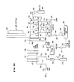
- Figure 1 is a fragmentary view of a sewage aeration system including a sewage aeration tank, an air supply main, means for introducing a mixture of aeration gas and cleaning gas into said air supply main, a downcomer pipe, distribution pipes, header pipes and diffusers.
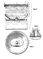
- Figure 2 is a perspective view of a section of header pipe and diffusers of Figure 1.
- Figure 3 is a vertical transverse cross section of the header pipe and one of the diffusers of Figure 2 taken on section line 3-3 of Figure 2.
- Figure 4 is a longitudinal cross section of the diffuser and pipe of Figure 3, the component parts of the diffuser being exploded for clarity.
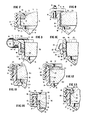
- Figure 5 is an enlarged portion of Figure 4 showing portions of the wall of the header pipe and the lower wall of the plenum, along with the details of the air flow regulator member which is in communication and connected with the air outlet and inlet openings in said pipe and lower wall. This figure also shows an optional lower valve member on the air flow regulator member.
- Figures 5A-D show the same portions of the header pipe and plenum walls as Figure 5 with alternate forms of air flow regulator members which may be substituted for those shown in Figures 4 and 5.
- Figure 6 is a plan view of the plenum of Figure 4.
- Figure 7 is an enlarged portion of Figure 3 showing the peripheral edge of the diffusion element in transverse cross section, along with portions of the plenum, retaining means and sealing means.
- Figures 8 to 14 show the same portion of the apparatus as Figure 7, but with varying modifications to the diffusion element retaining means and sealing means.
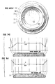
- Figure 15 is a vertical transverse cross section of the header pipe and one of the diffusers of Figure 2 wherein the plenum side walls are affixed directly to the pipe wall, whereby the upper surface of the header pipe serves as the bottom wall of the plenum.
- Figures 16 and 17 are plan and elevation views of a header pipe and diffuser wherein the diffuser has vertical side walls.
- Figure 18 is a vertical transverse cross section of header pipe and diffuser of Figure 16 taken at section 18-18 of Figure 16 showing a structure wherein the upper surface of the header pipe serves as the bottom wall of the plenum.
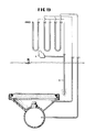
- Figure 19 is a sectional view, partly schematic, showing a portion of the gas distribution network, flow regulating means, a diffusion element and its holder, and means for determining pressure and flow data useful in the practice of the invention.
- Figure 20 is a diagrammatic illustration, partly in section, including a gas diffusion element, an apparatus for determining the bubble release pressure of the element and a graphical representation of the bubble release pressure and corresponding flow characteristics of the element.
- Figure 20A is an enlarged portion of the probe of Figure 20.
- Figure 20B is an enlarged and foreshortened portion of the element and bubble release pressure curve of Figure 20.
- Figures 21 through 29 are fragmentary, diagrammatic, transverse sectional views disclosing diffusion elements useful in accordance with the present invention and illustrative methods for manufacturing same.
- Figure 28A is a plan view from the top, of the diffusion element of Figure 28.
- Figure 30 is a transverse cross section of a diffusion element in accordance with Figure 27 and an associated bubble release pressure plot exemplary of said element.
- Figure 31 is a transverse cross section of a diffusion element in accordance with Figure 28 and an associated bubble release pressure plot exemplary of said element.
- Figures 32A and 32B are pressure versus flow diagrams illustrating the benefits of a preferred embodiment of the invention in which a plurality of diffusion elements each have their own individual flow regulating means.
- Figure 33 is a partly schematic diagram of the presently preferred embodiment of a tank-type sewage aeration system including means for supplying and mixing aeration gas and cleaning gas and for discharging same through area-release multi-pore diffusion elements.
- Figure 34 is a schematic diagram of testing apparatus for producing accelerated fouling of, and for cleaning, multi-pore diffusion elements.
- Figure 35 is a graph of the results of illustrative examples set forth below.
- Figure 36 is an enlargement of portions of certain of the curves illustrated in Figure 35.
- foulants Although the invention will most commonly be used in aeration systems for the biological treatment of wastewater, it is useful in the treatment of aqueous or non-aqueous liquids with or without biological and non-biological foulants. See the definition of foulants below.
- cleaning gas Any suitable cleaning gas which is aggressive towards the foulants may be used as cleaning gas for purposes of the present invention. See the definition of cleaning gas below.
- the treating gas is an oxygen-containing gas, especially air
- the cleaning gas is hydrogen chloride gas (HCl)
- the liquid medium is wastewater containing domestic sewage
- the treatment facility is a tank-type activated sludge plant.
- unrestrained deposition of foulants will normally cause a substantial increase in the dynamic wet pressure of the diffusion elements, or a substantial increase in the mean bubble release pressure of the elements, measured at the influent and/or effluent surface(s) of the elements, or a substantial increase in both of said pressures.
- substantial deposits of foulants concentrated at the gas effluent surfaces of the diffusion elements may result in appreciable increases of both the dynamic wet pressure of the elements and the mean bubble release pressure measured at the effluent surfaces, while resulting in no change in bubble release pressure at the influent surfaces.
- cleaning is conducted in such a manner as to restrain formation of foulant deposits in the diffusion elements.
- restraining are operations which prevent or retard the formation of such deposits or which remove at least a portion of accumulated deposits from time to time, whereby the extent of fouling of the diffusion elements is controlled.
- cleaning gas may be applied with sufficient frequency to prevent any appreciable amount of deposits from forming, in which case it could be possible that no increase in either the dynamic wet pressure or the mean bubble release pressure of the elements would be observed.
- restraining would include treatment with cleaning gas with a frequency which was not effective to completely prevent the formation of appreciable deposits of foulants in the diffusion elements, but which was sufficient to discourage the growth of organic or other foulants and thereby maintain the dynamic wet pressure and/or mean bubble release pressure of the elements within one or more of the ranges set forth above over an extended cycle of operation. Also, at different times and under different conditions a given plant may be operated in any of the modes described above, i.e. the prevention, retardation or removal mode.
- the cleaning gas may be applied continuously or intermittently, including application at sporadic or periodic time intervals.
- cleaning gas may be applied substantially continuously for an extended cycle of operation, following which the application of cleaning gas may be either suspended for a time or may be intermittent, for example, when the concentration of foulants in the liquid medium or treating gas is reduced for some reason, or when conditions in the process become less hospitable to the formation of foulant deposits.
- there may be continuous cleaning from time to time, for example when seasonal or other factors cause the concentration of foulants in the liquid medium or treating gas to increase to an unusually high level.
- the extent of fouling which is used to control the cleaning is characterized in terms of a level of dynamic wet pressure or mean bubble release pressure of the diffusion elements relative to the base condition of the elements, as defined above. This does not however imply that the application of cleaning gas must await the advent of sufficient fouling to create a measurable increase in the dynamic wet pressure and/or mean bubble release pressure of the diffusion elements.
- the cleaning gas could be applied intermittently but sufficiently frequently so that there would be no increase or only a very small increase of the dynamic wet pressure and/or mean bubble release pressure over the base condition of either of said pressures.
- the available pressure measuring equipment may not be sufficiently precise to measure the very small increase in pressure attributable to deposition of foulants between applications of cleaning gas.
- the increase in dynamic wet pressure level above base condition could be at least about 0.2, at least about 0.5 or at least about 0.7 inches of water gauge (0.05, 0.125 or 0.175 kpa, respectively) at 2 SCFM per square foot (0.01 m3/s per m2) of active gas discharge surface of the element.
- the increase in mean bubble release pressure above base condition could be at least about 0.2, at least about 0.5 or at least about 0.7 inches of water gauge (0.05, 0.125 or 0.175 kpa, respectively).
- gas cleaning may be initiated at or before the time when the dynamic wet pressure level of the elements has increased above their base condition by an amount which is equal or equivalent to about 25 inches or less (6.25 kpa), more preferably about 15 inches of less (3.75 kpa) and still more preferably about 7 inches of less (1.75 kpa), of water gauge at 2 SCFM per square foot (0.01 m3/s per m2) of active gas discharge surface.
- cleaning may be initiated when the mean bubble release pressure of the elements has increased relative to the base condition by about 25 inches or less (6.25 kpa), preferably about 15 inches or less (3.75 kpa) and still more preferably about 7 inches or less (1.75 kpa), of water gauge.
- Cleaning is conducted, i.e. the cleaning gas is applied in one or more periods of application, with a sufficient amount of cleaning gas to effect a substantial extent of cleaning which can for example be characterized in terms of a certain minimum reduction of any increase in dynamic wet pressure or of any increase in mean bubble release pressure which occurred as a result of fouling between a previous base condition and the commencement of cleaning.
- cleaning may be conducted until the reduction in the dynamic wet pressure, if any, corresponds to at least about 0.3, more preferably at least about 0.5 and still more preferably at least about 0.8 of any increase in dynamic wet pressure.
- cleaning may be conducted until the reduction in the mean bubble release pressure, if any, corresponds to at least about 0.5, more preferably at least about 0.8 and still more preferably at least about 0.9 of any increase in bubble release pressure.
- cleaning be conducted with sufficient frequency, employing a sufficient amount of cleaning gas, so that the diffusion elements can remain in contact with the liquid medium for extended cycles of operation with treating gas without removing diffusion elements from contact with liquid medium and/or without application of techniques other than gas cleaning to the diffusion elements.
- An object of the invention is to continue such contact and/or non-use of such other cleaning techniques, especially those involving removal of the diffusion elements from their holders, for extended cycles of operation of at least about two, three, five years, or more, including the entire design life of the element. With this objective in mind, it is considered best to apply cleaning gas continuously or intermittently to restrict any increase in the dynamic wet pressure or the mean bubble release pressure of the elements to zero to about 5 inches of water gauge (1.25 kpa) over their base condition.
- the flow of cleaning gas to the diffusion elements may be initiated, maintained, controlled or terminated in response to any variable or condition which is sufficiently related to or representative of the rate or extent of fouling to be effective in maintaining the dynamic wet pressure or mean bubble release pressure at or below the levels indicated above.
- any variable or condition which is sufficiently related to or representative of the rate or extent of fouling to be effective in maintaining the dynamic wet pressure or mean bubble release pressure at or below the levels indicated above.
- the flow of cleaning gas is initiated, maintained, controlled or terminated in response to a system condition which is more directly indicative of the dynamic wet pressure or mean bubble release pressure of the diffusion elements.
- system back pressure can in certain cases be sufficiently representative of the average dynamic wet pressure and/or bubble release pressure of the diffusion elements to serve as a basis for conducting intermittent or continuous gas cleaning.
- Increases and decreases in the aforementioned pressures may be detected by measurement of changes in the pressure in the conduits of the distribution network between the compressors (including blowers) and the flow regulating means through which the diffusion elements are supplied.
- increases and decreases in said pressures may be detected on the basis of variations in the flow of gases through the diffusion elements, all other conditions being equal or at least equivalent.
- Increases and decreases in said pressures may also be detected on the basis of the amount of additional power consumed in maintaining equivalent flow as the fouling of the elements progresses.
- the cleaning gas is applied simultaneously to diffusion elements arranged in groups ranging in number from about 10, more or less, to hundreds or thousands of such elements, and it should be understood that the foregoing limits of increase in dynamic wet pressure or mean bubble release pressure will not necessarily be applicable to all of the elements in such groups. Put differently, cleaning may be commenced when something less than all of the elements in a given group have reached the predetermined extent of fouling at which cleaning is to be commenced. Nor is there any intension of excluding the possibility that a minor portion of the elements may exceed the limits indicated above. Thus, the process may be conducted on the basis of the dynamic wet pressures or mean bubble release pressures of typical elements in such group or groups or on the basis of the estimated average condition of all the elements in the group or groups.
- any reduction in dynamic wet pressure which may occur during cleaning is postponed, with the objective of increasing insofar as possible the number of pores in the diffusion elements through which cleaning gas is caused to pass.
- a fouled diffusion element is cleaned, and that during cleaning no other steps are taken to maintain or alter dynamic wet pressure.
- the type of foulant is one which tends to manifest a decrease in dynamic wet pressure as cleaning proceeds.
- the present invention is preferably practiced in conjunction with postponement (including retardation) of at least a portion of any dynamic wet pressure reduction which may result from cleaning.
- This aspect of the invention is useful when cleaning is commenced at a dynamic wet pressure increase or mean bubble release pressure increase, above base condition, of about 25 or less inches of water gauge (6.25 kpa), and is particularly beneficial when practiced in conjunction with commencing cleaning at about 15 inches or less (3.75 kpa), and even more preferably at about 7 inches of less (1.75 kpa), of water gauge over base condition.
- a dynamic wet pressure increase or mean bubble release pressure increase above base condition
- Such step of postponement of dynamic wet pressure reduction may for example include doing any one or more of the following in any sequence for at least a sufficient portion of a cleaning cycle for obtaining appreciably better cleaning of the diffusion elements: increasing the dynamic wet pressure across the elements for a portion of the cycle; maintaining the dynamic wet pressure across the elements constant for a portion of the cycle; and/or, for a portion of the cycle, slowing the rate of decrease of dynamic wet pressure across the elements, e.g. to a rate slower than that rate of decrease which will result merely from cleaning (assuming all other conditions remain the same or equivalent).
- dynamic wet pressure is in effect the difference between the gas pressure at the influent surface of a diffusion element and the hydrostatic head in the liquid medium at the effluent surface of the element postponement of the dynamic wet pressure reduction attributable to gas cleaning can be practiced by controlling either said gas pressure, or said hydrostatic head, or both.
- the enhancement level is usually about 0.5 or more, preferably about 1 or more and most preferably about 2 or more inches of water gauge (0.125 kpa, 0.25 kpa or 0.5 kpa, respectively).
- the cleaning gas may be fed in any gas mixture in which the total pressure of all gases applied meets a criterion for enhancement set forth above, irrespective of the extent to which the individual gases contribute to the total gas pressure.
- a criterion for enhancement set forth above, irrespective of the extent to which the individual gases contribute to the total gas pressure.
- flow to the individual elements will generally increase and the dynamic wet pressure will generally decrease, all other independent variables remaining the same.
- Manipulation of some of the variables can result in control of the dynamic wet pressure to either hold it constant, or cause it to increase or cause it to decrease at a slower rate than would otherwise have occurred.
- This postponement of the reduction of dynamic wet pressure including reduction in its rate of decline, can have a favourable effect in cleaning, since it makes the cleaning gas available to more passages or for a longer period of time or both.
- This postponement or delay may be obtained by increasing the pressure in the plenums which deliver gas to the diffusion elements, and/or by reducing the hydrostatic head.
- Any suitable technique for increasing plenum pressure may be used to postpone dynamic wet pressure reduction. Suitable examples include increasing compressor output and/or adjusting valves in the system to provide a higher flow of air to the section being cleaned, relative to the remainder of those portions of the system having a common air supply.
- Any suitable technique for reducing hydrostatic head may be used to postpone dynamic wet pressure reduction. For example, one may conduct gas cleaning while the hydrostatic head is appreciably below its pre-cleaning operating head. Operating at diminished hydrostatic head includes reducing the submergence of the diffusion elements during at least a portion of the time during which cleaning is being conducted. For example, the level of liquid medium in the treatment tank may be lowered or, if the diffusion elements are mounted in the tank in arrays on lifting means for lifting them from the liquid medium, at least a portion of the diffusion elements may be raised to a higher submerged elevation in the medium using the lifting means.
- At least 40%, more preferably at least about 60% and most preferably at least about 80% of the cleaning gas be discharged from the diffusion elements while sufficient enhanced pressure is being supplied, and/or while sufficient amounts of surface active agent(s) are being maintained in contact with the diffusion elements/liquid medium interface, for promoting cleaning.
- any of the foregoing techniques which result in postponement of dynamic wet pressure reduction or comparable effects can be applied to the gas distribution network or to any selected portion thereof, including individual tanks in multi-tank plants and individual groups of diffusion elements constituting only part of the diffusion elements in a given tank.
- dynamic wet pressure and system back pressure values are sometimes expressed in terms of numerical pressure values referenced to a given reference rate, e.g. 2 SCFM per square foot (0.01 m3/s per m2) of active gas discharge area as designed, manufactured or installed.
- a given reference rate e.g. 2 SCFM per square foot (0.01 m3/s per m2) of active gas discharge area as designed, manufactured or installed.
- Flowmeters are commercially available which are capable of measuring flow with the requisite accuracy, and many are available with conversion tables for converting the registered flow back to standard cubic feet per minute at whatever conditions of temperature, pressure and humidity have been adopted as standard for the plant in question. Also, it is apparent that a general or special purpose computer may be provided and programmed to make the necessary conversions of data, and, if desired, actuate process control devices.
- the plant and diffusion elements may have been designed for a different flow rate than 2 SCFM per square foot (0.01 m3/s per m2), or may have been operated successfully over an extended period, e.g. ninety (90) days, at a daily average rate of flow differing substantially from 2 SCFM per square foot (0.01 m3/s per m2).
- an increase in dynamic wet pressure at one of these flow rates for initiating or otherwise controlling cleaning.
- the plant could be operated in such a manner that cleaning was initiated before the increase in dynamic wet pressure as compared to the base condition, exceeded 25 inches of water gauge (6.25 kpa), the base operating condition and the 25 inches of water gauge (6.25 kpa) both being referenced to a flow rate equal to the daily average of the flow rate through the plant for the last 90 days immediately prior to the commencement of cleaning. Changes in reference flow rate may be made for the system back pressure values as well.
- the rate of application of cleaning gas, and the concentration of cleaning gas in admixture with other gases may also be varied considerably; we have observed that at lower rates or concentrations cleaning gas must be applied over a longer time interval, while higher rates and concentrations are able to effect cleaning in a shorter time interval. It is however preferred to apply the cleaning gas at a sufficient rate or concentration for effecting the indicated extent of cleaning within a period of about eight (8) hours or less.
- the concentration of cleaning gas in a mixture of cleaning gas with treatment gas may be expressed in mole fraction of cleaning gas in the mixture and/or by the equilibrium concentration, defined hereinafter, which results upon saturating a liquid sample with the medium.
- concentration to be used can be selected on the basis of various factors, including the solubility of the gas in the liquid medium, the specific aggressiveness of the liquid solution of cleaning gas to the type of foulant deposit present and, in electrolytes, the degrees of ionization of the resultant solutions.
- solubility constant and degree of ionization are particularly significant. In that instance pH, as well as gas phase mole fraction and equilibrium value, may be used as means of measurement and definition.
- the concentration and dosage of cleaning gas should however be an amount which is insufficient to substantially impair overall metabolic activity of the micro-organisms in the tank as a whole.
- water vapour including either water vapour which has or has not been intentionally added to the system.
- water vapour may enter the system and become mixed with the cleaning gas because the water vapour is a normal or usual component of certain kinds of treating gas (e.g. the humidity in air when the latter is used as treating gas).
- the cleaning gas and water vapour may be brought into admixture prior to or subsequent to the introduction of the cleaning gas into the above mentioned network.
- the cleaning gas may be dissolved in water, followed by passage of the treating gas through the water to pick up cleaning gas and water vapours and then by introduction of the resultant mixture into the network.
- the network often contains substantial quantities of condensed water vapour which entered the system as a component of aeration air; thus the cleaning gas and water vapour may become mixed as a result of contact and admixture of water vapour held in the network with cleaning gas, or with a mixture of cleaning gas and treating gas that has been formed prior to contacting the condensed water.
- peak cleaning effectiveness may not necessarily be attained until all or a substantial quantity of the condensed water has been purged from the system or the condensed water has absorbed a substantial quantity of, or become substantially saturated with, cleaning gas. If foulant deposits form at a location in the diffusion element which is not readily supplied with water by the liquid medium or treating gas, it can be beneficial to supply water vapour in admixture with the cleaning gas for forming aggressive aqueous solutions that assist in cleaning.
- the treating gas may for example be fed with the usual compressor or blower and overall system pressure or flow control means familiar to those skilled in the art.
- the cleaning gas may be fed from a storage tank containing a substantial supply of said gas under high pressure via a conventional flow controller and measuring means.
- said distribution network also includes measuring means which are preferably, but not necessarily, located in a submerged portion of said tank, for measuring temperature, pressure and flow of gas through said network or through representative diffusion elements with sufficient precision for maintaining the dynamic wet pressure across the diffusion elements in a range not to exceed about 25 inches (6.25 kpa), more preferably about 15 inches or less (3.75 kpa), and still more preferably about 7 inches or less (1.75 kpa) of water gauge above said base condition.
- measuring means are preferably, but not necessarily, located in a submerged portion of said tank, for measuring temperature, pressure and flow of gas through said network or through representative diffusion elements with sufficient precision for maintaining the dynamic wet pressure across the diffusion elements in a range not to exceed about 25 inches (6.25 kpa), more preferably about 15 inches or less (3.75 kpa), and still more preferably about 7 inches or less (1.75 kpa) of water gauge above said base condition.
- the gas distribution network may be constructed of any suitable material, including for instance, metallic, resin-lined metallic, and rigid resin pipe, including reinforced or unreinforced thermoplastic and thermoset resin pipe. It is desirable to transmit the cleaning gas to the diffusion elements through a portion of the above mentioned network which is formed of synthetic resinous material. Other portions of the network may be formed of other material, including for example metallic conduits and fittings. According to a particularly preferred embodiment of the invention the cleaning gas is first brought into admixture with the treating gas at a submerged location in the network. This facilitates the use of metallic conduits in the non-submerged portions of the network, including for example those conduits, such as downcomer pipes, which convey the treating gas from a position above the surface of the liquid medium down into the liquid medium.
- That portion of the gas distribution network which is exposed to the aggressive mixtures is composed of conduit having internal surfaces of acid resistant synthetic polymeric material.
- a synthetic resinous pipe having a load bearing wall of polymeric material which is preferred, it should have a tensile strength of about 2000 to about 60,000 psi (13.8 ⁇ 106 Pa to 41.4 ⁇ 107 Pa) a flexural modulus of about 4 ⁇ 104 to about 4 ⁇ 106 psi (2.76 ⁇ 108 to 2.76 ⁇ 1010 Pa) and a pipe stiffness of about 10 to about 1000 psi (6.9 ⁇ 104 Pa to 6.9 ⁇ 106 Pa), by ASTM D-2412.
- the conduit walls are formed of such synthetic polymeric materials as rigid polyvinyl chloride (PVC), acrylonitrile-butadiene-styrene (ABS) or other suitable resinous materials.
- PVC rigid polyvinyl chloride
- ABS acrylonitrile-butadiene-styrene
- these same materials may also be and preferably are embodied in the construction of the flow regulating means and diffusion element holders, although it should be understood that elastomeric materials resistant to the cleaning gases may be employed in certain of the flow regulating means and in the sealing means.
- Whatever materials are used should be chosen with due regard to resistance to corrosion, weather, collapse and impact. Suitable provision (not shown) should be made for expansion and contraction where necessary.
- the flow regulator means may be at least in part integral or non-integral with the holders for the diffusion elements. Mounting of the flow regulators within or without the holders is acceptable, but the most convenient arrangement is within the holders and therefore such arrangement is preferred.
- the flow regulators employed in accordance with the invention may be of any desired type, such as passive and active flow regulator means, including those with varying pressure response characteristics. For instance, one may employ flow regulator means which respond exponentially to changes in pressure, such as for instance fixed orifices, or those which respond in a more linear fashion, such as for instance passages with large ratios of length to cross sectional area. Passages which change their cross-section in response to pressure changes are also contemplated, including those which can perform a valving function and those which are capable only of uni-directional flow.
- the diffusion elements may be supported by suitable holders, each of which at least partly encloses a plenum (to be discussed below) and includes a support surface against which a peripheral surface portion of a diffusion element may be supportively engaged with the aid of restraining means and/or of sealing means (also to be discussed below).
- suitable holders each of which at least partly encloses a plenum (to be discussed below) and includes a support surface against which a peripheral surface portion of a diffusion element may be supportively engaged with the aid of restraining means and/or of sealing means (also to be discussed below).
- suitable holders each of which at least partly encloses a plenum (to be discussed below) and includes a support surface against which a peripheral surface portion of a diffusion element may be supportively engaged with the aid of restraining means and/or of sealing means (also to be discussed below).
- suitable holders each of which at least partly encloses a plenum (to be discussed below) and includes a support surface against which a peripheral surface portion
- the plenum may be of any suitable material, it also is preferably of synthetic polymeric material, which may be reinforced and preferably has the physical properties described above in connection with the preferred pipe.
- the holders may be fashioned by any appropriate forming process, such as for instance, injection moulding, lay up and spray up techniques.
- the plenums through which the respective flow regulating means discharge gas to the gas influent surfaces of the diffusion elements are gas chambers defined by wall means which provide the gases with ready access, and an opportunity for relatively uniform distribution, to said influent surfaces.
- the plenums will normally but not necessarily be within the holders. Usually one or more walls of each plenum will be defined by the influent surface of the diffusion element itself and the other walls of the plenum will be defined by internal surfaces of the holder. In certain cases the majority of the wall areas in the plenums may be defined by the influent surfaces of the diffusion elements, such as where the elements are in the form of elongated tubes of relatively small diameter compared to their length.
- the holders as well as their respective retaining means can take a wide variety of forms, including those which secure the diffusion elements by direct or indirect contact about their entire peripheries, or at spaced points about their peripheries or at other locations, such as for example the centre bolt arrangements shown for instance in U.S. Patents 4,046,845 to Richard K. Veeder and 3,532,272 to Eric S. Branton.
- attachment of the diffuser elements by central or other fasteners which extend through holes in the active diffusion surface produce detrimental effects, the prediction of which would not have been obvious.
- sealing between element and plenum is accomplished through vertically loaded elastomeric gaskets.
- the required loading to effect adequate seal of the porous diffuser element may be high, e.g. 50 pounds/lineal inch (8.86 kg/cm) of seal. Greater strength and rigidity of the diffuser and plenum is required to distribute these forces about the periphery than the preferred embodiments of this invention wherein continuous peripheral clamping or retaining is employed.
- fasteners extending through the element into the plenum typically require holes with clearance. Unless the interiors of the holes are sealed in their entireties, free passage of air is provided in these clearances that promotes excessive flow from the diffuser elements in the vicinity of the fastener. Enlarging the sealed area under the lower horizontal surface of the retaining means, to lengthen the path of air from the clearance zone to the diffuser surface does not correct this deficiency, since the reduction in unit flow (flux) in the vicinity of the fastener resulting from the additional sealed area at the surface, similarly reduces the frictional pressure drop in that region, and the problem of non-uniform distribution persists.
- the detrimental effects of the "through-hole" type fasteners above described may be overcome by the use of the preferred peripheral clamping or retaining methods employed in our invention.
- the applicable retaining means are, for example, those including clips, clamps and rings which clamp or merely restrain, secured to the plenum by bolts, hooks, threads and other fastening means.
- Suitable sealing means may be fabricated from a wide variety of materials in a wide variety of forms. For example, one may employ various plastics and rubbery elastomers.
- the sealing means may be one or more members of circular, flat or other cross-section, including special profiles matched to the shape of the diffusion element and/or its support means.
- the requisite shapes can be produced by any suitable forming process, such as for instance extrusion, casting and other moulding techniques.
- the invention contemplates the use of sealing means which are adherent or attached to the diffusion elements, such as those which are clamped or bonded in place, and those which are not adherent or attached.
- sealing means which are neither adherent nor attached to the diffusion elements, and which are preferred in the present invention are preferably held against the elements by the structure of the holder, by the structure of the retaining means described above, by the structure of the diffusion element itself, and preferably by a combination of the foregoing.
- Disposition of the sealing means adjacent the periphery of the diffusion element includes placement inside and/or outside the outline of the periphery of the element as viewed in plan view and at varying elevations above, below and/or along the side of the element, but the sealing means preferably makes contact with an upper edge of a vertical (including near vertical) side surface of the element as described in greater detail below.
- a wide variety of diffusion elements may be employed, made of varying materials in varying configurations.
- the invention is practiced with multi-pore diffusion elements, members containing a multitude of closely spaced passages or pores of small diameter defining paths for the discharge of gases into liquid media.
- Such pores or passages may be of any suitable shape, size and length, their shape being determined to a certain extent by the method of producing the element.
- a porous body may be formed by solidifying a shaped mixture of water-insoluble molten material and water soluble solid particles, followed by leaching out the soluble particles.
- a porous member may be formed for example by building up layers of fabric formed from fibres or filaments.
- the diffusion elements and their pores are formed by the bonding of solid particles together in a mass in which the pores are formed by the spaces extant between bonded particles.
- the particles may be bonded with or without an adhesive or other bonding agent.
- the elements may, for instance, be formed of organic or inorganic materials in particulate and/or fibrous forms.
- An exemplary organic material is particles of fusible polymeric material as disclosed in U.S. patent 3,970,731.
- Exemplary of inorganic materials are metal and ceramic powders, including for example, alumina, silica, mullite, and various clays.
- the finely divided materials are generally shaped and compacted under pressure, and, if necessary, heated or fired to fully develop the necessary coherency. Bonding with organic or inorganic binders is contemplated, and the finely divided particles and/or fibres may be bound together by organic adhesive bonds, ceramic or fusion bonding or sintering.
- the diffusion elements may be formed in any useful shape.
- they may be formed in the shape of plates, defining a flat or curved surface, tubes or domes.
- the applicable shapes are those which appear round, oval, square, rectangular, polygonal and irregular in plan view, and those which appear substantially horizontal in transverse cross section, including those which are truly flat and those which are only generally horizontal, in the sense of including non-horizontal surfaces but including a portion which extends in a generally horizontal direction.
- the elements may have plain vertical or inclined edges, with or without steps and the edge portions may include bevels, rounded portions, grooves and the like.
- the applicable elements preferably have active gas discharge surfaces which are free of bubble emitting macro openings, such as those shown for instance in U.S. Patent 3,970,731 to Oskmann.
- the element is such that it will emit fine bubbles from random locations throughout the gas discharge surface.
- the gas infusion surface of the element is free of air transmitting macro holes longer than 0.3T wherein T is the average thickness of the element weighted on an area basis, or is free of such holes.
- a macro hole is an intentionally or unitentionally produced hole larger than that normally produced by compaction of the particulate material. It is beneficial if substantially all gas paths through the body of the element to its gas discharge surface, as installed in the plenum or other holder, are about the same length.
- a diffusion element having a bubble release pressure in the range of about 2 to about 20 (0.5 to 5.0 kpa), preferably about 3 to 15 (0.75 to 3.75 kpa) and more preferably about 4 to about 10 (1 to 2.5 kpa) inches of water gauge.
- the optimum bubble release pressure is considered to be about 7 inches (1.75 kpa).
- the values given are for bubble release pressure in water of new elements as manufactured, i.e. prior to use.
- a technique for determining bubble release pressure, and other preferred characteristics for the diffusion elements used in the present invention, are disclosed in U.S.-A-4 261 933. It is also preferred to fabricate the element of hydrophilic materials, i.e.
- the element is one whose sides, including for example extreme vertical edges and vertical or near vertical surfaces of steps near the periphery of the element, are porous, at least semi-permeable and free of adherent material preventing bubble emission.
- the preferred elements have a specific permeability when new of about 6 to about 200 SCFM at 2 inches of water gauge (0.03 to 1.0 m3/s per m2 at 0.5 kpa).
- the thickness of the elements may be uniform throughout or may vary when viewed in horizontal cross-section.
- a particularly desirable characteristic of the preferred diffusion elements is that of relative uniformity of bubble release pressure throughout the gas effluent surfaces of the elements.
- Such uniformity may be attained in any suitable fashion, such as for example by the techniques disclosed in the above-mentioned U.S.-A-4 261 933.
- the standard deviation of at least 5 bubble release pressure measurements taken along each of two perpendicular lines across the diffusion element effluent surface is less than 0.25 and preferably less than 0.05.
- the most preferred diffusion elements are those which are formed of sintered or bonded particles in accordance with the teachings of the aforesaid U.S.-A-4 261 933 and of U.S.-A-4 261 932.
- the element be so supported that all portions thereof which emit air to the surrounding liquid may have ready access to replacement water, to maintain such emitting portions in contact with water and subject to the influence of surface tension.
- it is preferred to avoid a situation in which a side surface of the element is adjacent to a crevice which can be swept clear and kept clear of water by the air discharged from the side surface.
- the air emanating from the element adjacent said crevice does not have to overcome the effects of surface tension, causing air to be preferentially routed to that portion of the element and thus correspondingly impairing the uniformity of distribution of flow from the element.
- the supporting means and other associated structure are so shaped and positioned that any exposed portion of the element capable of emitting air to the liquid has ready access to replacement liquid, so that the surface is not swept and kept clear of water, the aforementioned distribution difficulty can be avoided.
- a portion of the diffusion element which would otherwise discharge air into a crevice of the type described above can be sealed by appropriately positioning a seal of lesser height than the element, by applying an impermeable coating to the surface, or by sufficiently compressing such sides or any portion thereof having access to water so as to render same substantially impermeable.
- the preferred diffusion elements include sides which are porous, at least semi-permeable, free of adherent material preventing bubble emission and "vertical" (including near vertical, e.g.
- the sealing means is of lesser height than the diffusion element, but is positioned at an upper edge defined by the intersection of said vertical or near vertical sides and an upward facing portion of the upper gas discharge surface of the element.
- the diffusion elements will generally be mounted in a natural or man-made water impound such as a lake, lagoon or tank, most commonly a large tank of concrete construction for activated sludge treatment of domestic sewage.
- the diffusion elements will be mounted in the water impound in one or more arrays connected to the gas distribution network and may be supported at one or more elevations, assuming suitable pressure or flow controls or separate compressors are provided to insure proper distribution of the aeration gas to the elements at the various levels.
- Figures 1 through 18 disclose specific embodiments of particularly preferred forms of apparatus useful in connection with the invention.
- Figure 1 shows a sewage aeration tank 1 including a bottom 2 with side and end walls 3 and 4 to contain a body of sewage which is to be aerated.
- a compressor 5 is provided to feed filtered atmospheric air through valve 6A, flow indicator 7A, and branch conduit 18A to air main 8.
- Storage tank 19 contains a supply of cleaning gas stored at high pressure which may be discharged to air main 8 in controlled or predetermined admixture with the compressed air via valve 6B, flow indicator 7B and branch conduit 18B.
- valve 6A and 6B By manipulation of valve 6A and 6B one may commence, terminate or control the flow of aerating and cleaning gas whereby the foregoing elements constitute means for feeding aeration gas and for continuously or intermittently feeding a mixture of aeration gas and cleaning gas to the distribution network.
- the distribution network comprises air main 8 which is generally supported above the level of liquid in the tank 1, and which feeds into a downcomer pipe 9, extending vertically from air main 8 to a horizontally disposed distributor pipe 10 supported substantially horizontally a short distance above bottom 2.
- Parallel rows of air header pipe 11, also supported horizontally a short distance above bottom 2, are fed by distributor pipe 10.
- the spacing, in a horizontal plane, or air headers 11 and diffusers 12 is determined on the basis of criteria known to persons skilled in the art.
- air main 8 and downcomer pipe 9 are of metal, while distributor pipe 10 and branch conduit 18B are of synthetic resin; downcomer 9 and pipe 10 are connected at a gas tight pipe coupling (not shown).
- conduit 18B enters but does not communicate with air main 8 at the point of intersection shown in Figure 1 and extends continuously within air main 8 and downcomer 9 to a discharge outlet in pipe 10 downstream of the coupling and below the surface of the liquid in the tank.
- conduit 18B extends, separately from air main 8, directly to a submerged connection with pipe 10 downstream of the coupling.
- Figure 2 shows in perspective a broken out and enlarged portion of one of the air headers 11 with its diffusers 12.
- header pipe 11 has air outlet openings 13 formed at longitudinally spaced intervals along its top centre line to feed air into the respective plenums 14 of diffusers 12.
- Each plenum 14 includes lower wall means 15. All or at least a substantial portion of the lower wall means is circular in transverse cross section and conforms to the outer surface 16 of pipe 11.
- Lower wall 15 may be held in close fitting engagement with pipe 11 in a variety of ways, including various mechanical arrangements, such as clamps or straps but preferably by bonding to the pipe. In general any bonding technique may be employed, such as for instance, adhesive bonding; but if the pipe is of polymeric material, which is preferred, the attachment may also be made by solvent or thermal (including sonic) welding.
- the plenum may be sealed to the pipe by the same means used in attachment, or by different means.
- one may provide an elastomeric seal between the plenum lower walls means and pipe outer surface 16, or the seal may be provided by the welding or adhesive referred to above.
- lower wall means 15 be held in close fitting engagement with a substantial portion of the length of the pipe outer surface 16 (as shown in Figure 4) and of the transverse cross section of the pipe.
- lower wall 15 conforms and engages with the transverse cross section of the pipe through an arc of at least about 20°, more preferably about 45 or more degrees and most preferably about 70 or more degrees, at least in the mid portion 17 ( Figure 4) of the lower wall means.
- the arc is about 90°.
- lower wall means 15 includes an air inlet opening 22, around which there may be provided a small upstanding boss 23 ( Figure 3) on the inner surface of plenum lower wall means 15. Air outlet opening 13 and air inlet opening 22 are maintained in registry with one another.
- the system is provided with an air flow regulator member, one possible example of which is indicated by reference numeral 24.
- an air flow regulator member one possible example of which is indicated by reference numeral 24.
- a combined bonded assembly is formed by the pipe, by lower wall means 15 and by the air flow regulator member or a sleeve member 25 in which the air flow regulator member is mounted.
- the air flow regulator member 24 and various embodiments thereof will be discussed in greater detail below.
- the lower wall means 15 may be of any desired shape as viewed in horizontal plan view. It may for instance have a square, rectangular, circular or oval outline, the latter being preferred.
- Air inlet opening 22 and regulator 24 are both preferably within this outline as viewed in plan view.
- FIG. 5 shows the regulator 24 of Figures 3 and 4 enlarged and in longitudinal cross section.
- the regulator is a plug member having a central void to communicate through the open bottom of sleeve 25 with the interior of pipe 11.
- Extending laterally from recess 32 are a pair of horizontal orifices 33 communicating with the interior of plenum 14. As shown in Figures 3 and 4 these orifices 33 are in direct open communication with the interior of plenum 14.
- the orifices have a uni-directional flow characteristic, i.e. they function as check valves. Such characteristic is valuable if there is a temporary loss of air pressure in header pipe 11.
- the uni-directional flow characteristic of the regulator tends to maintain pressure within plenum 14, thus discouraging backflow of liquid from the exterior of the diffuser through the diffusion element 35 into the plenum. This reduces the difficulties of starting up the system when pressure is restored. Backflow of sewage-laden water through diffusion element 35 or regulator 24 tends to plug these components, leading to possible complete plugging or non-uniform distribution of air flow through the element and/or system when the flow of air under pressure is restored.
- FIG. 5A discloses a pressure responsive uni-directional flow regulator commonly referred to as a "duckbill".
- the duckbill is normally made of flexible and elastic material in a lip-like configuration reminiscent of a duck's bill and having lips terminating in a slit which is normally closed.
- the duckbill is mounted in a sleeve 25A recessed in the plenum lower wall 15 and header pipe 11, so that the duckbill may be mainly within the outline of the header pipe.
- the duckbill has a cylindrical barrel portion 37, lips 38 terminating in a horizontal slit 39 and an annular flange portion 40 which is confined in sleeve 25A by a concentric collar 41 fixed within sleeve 25A.
- An inwardly directed flange 42 with central opening 43 at the lower end of sleeve 25A supports the duckbill from beneath and provides communication with the interior of cylindrical barrel 37, by means of which air is communicated from the interior of the pipe between lips 38 and through slit 39 into the interior of plenum 14.
- the orifice provided upon opening of slit 39 varies in accordance with the pressure but closes on termination of inward flow relative to the plenum.
- this regulator acts as a check valve.
- Figures 5B and 5C illustrate a flow regulator comprising a plurality of passages having a large ratio of length to cross sectional area.
- the regulator of Figure 5B shown in partial section, includes a stepped cylindrical housing 47 of which lower end 48, having a reduced cross-section, closely fits within the air outlet and inlet openings 13 and 22 of header pipe 11 and plenum lower wall 15, which components may if desired be welded into a unitary assembly.
- Housing 47 includes a circular lower base 49 with air inlet holes 50 more clearly shown in Figure 5C, and serves as the base for a central threaded post 51 which extends above the top of housing 47.
- an annular porous plug 52 which substantially fills the space between post 51 and the side walls of housing 47.
- the flap On termination of upward flow through porous plug 52, or upon the commencement of flow in the opposite direction, the flap closes, preventing reverse flow of gas back towards header pipe 11.
- the bypassing effects described above can be controlled by impermeable coatings on the walls of the centre hole and periphery of plug 52.
- Figure 5D illustrates a readily removable and replaceable flow regulator.
- the regulator is partly within plenum 14 and partly within pipe 11.
- a sleeve 25B is positioned in air outlet and inlet holes 13 and 22 of header pipe 11 and plenum lower wall 15.
- the regulator in Figure 5D includes a cylindrical void or recess 32 open at the bottom and, in communication therewith, a horizontal orifice 33.
- the cylindrical barrel portion 60 of this regulator closely fits within the cylindrical bore of sleeve 25B and has two annular grooves, upper and lower grooves 61 and 62 respectively, in which upper and lower O-rings 63 and 64 are mounted.
- Upper O-ring 63 is of slightly larger outer diameter than the inner diameter of sleeve 25B, and effectively seals off flow from header pipe 11 to the interior of plenum 14 through the space between cylindrical barrel 60 and the inner surface of sleeve 25B.
- Lower O-ring 64 has a somewhat larger external diameter which enables it to act as a catch to hold the flow regulator in place.
- O-ring 64 is sufficiently compressible and has sufficient space in groove 62 so that cylindrical barrel portion 60, with O-ring 64 in place of groove 62, may be introduced into the upper end of sleeve 25B and forced through sleeve 25B to the position shown in Figure 5D, at which point O-ring 64 expands against the tapered lower inner surface 65 which forms a detent at the lower end of sleeve 25B.
- O-ring 64 has sufficient exterior diameter to hold the regulator member in place under normal operating pressure, but the regulator may be withdrawn without destroying the regulator or the sleeve 25B, and may be replaced with a regulator of differing flow characteristics. This is beneficial when it becomes necessary to replace diffusion element 35 ( Figures 3 and 4) with elements having different head loss characteristics, or in the event it is desired to alter the overall operating characteristics of the aeration system.
- side wall means 26 is connected with the periphery of lower wall means 15.
- the side wall may be vertical, or inclined inwardly or outwardly from the lower wall means.
- the side wall means is connected with the entire periphery of the lower wall means, and is inclined upwardly and outwardly from the lower wall means.
- Diffusion element supporting means spaced upwardly and outwardly from the lower wall means, are provided on said side wall means.
- Such supporting means may for instance include a horizontal annular shelf 27 with inner and outer diameters respectively smaller and larger than the diameter of the lower edge of the diffusion element 35, to be described in greater detail below.
- Shelf 27 may, if desired, be part of a step in side wall means 26, the rising portion of which step comprises a cylindrical generally upright wall 21.
- the diffusion element supporting means may be in any desired position on side wall means 26, but is preferably at (in, on or near) the extreme upward and outward projection of wall means 26.
- wall means 26 is of a conical shape.
- the plenum includes an integral generally upstanding wall 28 which, when viewed in plan view, surrounds the diffusion element supporting means, e.g. annular horizontal shelf 27.
- upstanding wall 28 has a height which is about equal to the height of the diffusion element 35.
- the height of wall 28 may be equal to or slightly greater or less than the height of the diffusion element.
- Wall 28 has an inner surface 29, also generally upstanding, an upper edge 30 and threaded outer surface 31.
- the shelf 27 and generally upstanding wall 28 therefore can, in the preferred embodiment, provide a socket to receive diffusion element 35, in which substantially the entire height of diffusion element 35 is recessed as shown in Figure 3 and in the enlargement in Figure 7.
- the most preferred diffusion element is a ceramic plate of circular outlet having a stepped edge, depicted in Figures 3 and 4, and include circular central flat area 70, annular bevelled edge 71, annular flat surface 72, outer annular bevelled surface 73 and horizontal annular surface 74, whose respective outer diameters are 4.5, 6.5, 7.6, 8.7, and 9.25 inches respectively (11.43, 16.51, 19.3, 22.1 and 23.49 cm, respectively).
- Surface 70 lies 0.070 inch (0.178 cm) below surface 72.
- Bevelled surface 73 is at an angle of inclination of 25° relative to the horizontal.
- the respective overall heights of horizontal annular surface 74, the top edge of vertical side surface 75 and horizontal flat surface 72 are 0.5, 0.7 and 1.0 inch respectively (1.27, 1.78 and 2.54 cm, respectively).
- the plate is formed from a mix containing particles of alumina with mean transverse and longitudinal dimensions of 0.020 and 0.032 inch (0.051 and 0.081 cm) respectively, and 20 parts by weight of ceramic bonding agent, per hundred parts by weight of alumina particles.
- the mix is compacted in a press having a ram with a planar surface and a cylindrical die cavity having a bottom wall with a shape corresponding to the upper surface of diffusion element 35.
- the sides of the die cavity and the ram correspond in diameter with the peripheral edge 76 of diffusion element 35 the height of the die cavity from its bottom surface to its upper edge being 1.5 inches (3.8 cm).
- the mix is poured into the cavity in excess, is struck off level with the top of the die and is compressed to the dimensions previously given under a pressure of approximately 900 psi (6.2 ⁇ 106 Pa).
- the resultant compact after removal from the press, is fired in a kiln at a temperature sufficient to fuse the bonding agent and is then gradually cooled.
- the resultant product is a coherent porous ceramic diffusion element having a specific permeability of 25 SCFM ⁇ 3 SCFM (0.125 ⁇ 0.015 m3/s per m2).
- the diffusion element is supported by and preferably nests within the plenum on the diffusion element supporting means.
- a sealing means is provided adjacent the periphery of the diffusion element for preventing leakage of air past the periphery of the element.
- a polyisoprene O-ring 80 having a Shore A Durometer hardness of about 40 ⁇ 3, nests in an annular step formed about the upper portion of the peripheral surface of diffusion element 35.
- the diameter of the cross section of O-ring 80 preferably slightly exceeds both the spacing between inner surface 29 of plenum side wall means 26 and opposed, facing vertical or near vertical side 75 of element 35, and the height of vertical or near vertical surface 75.
- the preferred retaining means of the present invention shown in Figures 3, 4 and 7 is an internally threaded clamping ring 84 including a cylindrical member 85 having internal threads 86 matching external threads 31 on side wall means 28 of the plenum. Cylindrical member 85 has attached to it above the thread 86 a flange 88 which extends inwardly over generally upstanding wall 28 of the plenum and at least partly across the top of sealing means 80.
- the said flange 88 leaves the upper inner quadrant of the cross section of the O-ring 80 uncovered (shown in greater detail in Figure 7) while clamping the O-ring with sufficient force to press it in tight engagement with at least the uppermost portion of vertical side portion 75 closely adjacent the edge 89 between side 75 and the upwardly facing adjacent surface 73, thereby avoiding formation of a crevice at the side of the diffusion element which would be in communication with the overlying water and could evacuate itself.
- FIGs 8 through 14 show alternative but less preferred embodiments of the combination of plenum, diffusion element, sealing means and retaining means which may nevertheless be used successfully in the invention.
- Each of these various embodiments has in common a plenum side wall means 26, annular horizontal shelf 27, and generally upstanding wall means 28 which is about of equal height with the diffuser element and which faces the opposed peripheral surface or surfaces of the diffusion element which is indicated by reference numerals 35 and 35A through 35G.
- generally upstanding wall means 28 is provided with peripheral flange 90 and circumferentially spaced bolt holes 91 through which extend bolts 93 to clamp a plurality of circumferentially spaced clips 92 against the respective upper surface of flange 90 and diffusion element 35A.
- An elastomeric band or hoop member 95 serves as sealing means.
- the hoop or band may have an unstretched inside diameter of about 85% of the outside diameter of diffusion element 35A, and is of slightly greater width than the vertical thickness of the diffusion element.
- the extra width of the band forms an inturned upper edge 97, an inturned lower edge 98 and a cylindrical centre portion 96, which respectively enclose the upper and lower edges 99 and 100 of the element.
- Inturned lower edge 98 bearing against annular horizontal shelf 27, seals the interior of the plenum from the vertical space between upstanding wall 28 and element 35A.
- Cylindrical portion 96 of the elastomeric band prevents air from passing peripherally out of diffusion element 35A into the crevice between itself and upstanding wall means 28.
- This is an example of retaining means which engages only the element and not the sealing means, and does not contact the entire periphery of the element.
- the embodiment of Figure 9 includes in its generally upstanding wall means 28 a second horizontal shelf 105 and, at the upper edge of said wall means, an outwardly extending generally horizontal flange 106.
- the peripheral edge of diffusion element 35B is provided with an impermeable coating 107 throughout the height of its peripheral surface, bears laterally against O-ring sealing means 80 which rests on shelf 105, and has an interference fit between diffusion element 35B and wall means 28.
- O-ring 80 is retained in place, i.e. prevented from upward movement, by a retaining ring 108 of cylindrical configuration having an inner surface 109 about which are situated a plurality of circumferentially spaced inwardly projecting lugs 110 which bear down at widely spaced points, with limited inward projection, on the upper surface of element 35B.
- Retaining ring 108 also includes an integral outwardly extending annular flange member 111 which rests upon and generally coincides with the outwardly extending flange 106 connected with wall means 28. These two flanges are held together by a split ring clamp 116 of generally C-shaped cross section having in transverse cross section limbs 112, 113 with curved inner faces which engage similarly shaped annular detents 114, 115 in the respective lower and upper surfaces of the flanges.
- split ring clamp 116 The vertical flexibility of limbs 112, 113, and a radial split (not shown) in split ring clamp 116 enable the latter to act as a snap action clamp to hold flange 111 and its integral retaining ring 106 firmly together, while lugs 110 secure the diffusion element 35B in place and the lower surface of ring 108 does not clamp, but does not prevent upward movement of O-ring 80.
- the embodiment of Figure 10 is similar in many respects to that shown in Figure 9.
- the side of diffusion element 35C has an impermeable coating 107 and faces generally upstanding wall means 28.
- the latter as in the previous embodiment, includes a second annular horizontal shelf 105 upon which rests O-ring 80, the latter being held in place by a retaining ring 108 with inner surface 109 and lugs 110.
- upstanding wall 28 has an integral catch 120 formed about the entire periphery of its outer circumference 121, and retaining ring 108 has a plurality of circumferentially spaced outwardly downwardly and inwardly extending hooks 122 for engaging the catch 120, whereby ring 108 is held in place preventing upward movement of O-ring 80 and holding diffusion element 35C securely in place with lugs 110.
- annular horizontal shelf 27 includes an inner upstanding lip 27A which helps retain in place a sealing means 125 of substantially rectangular cross section, upon which rests the marginal edge of the lower surface of diffusion element 35D.
- the side 127 or periphery of element 35D is in opposed, facing relationship with generally upstanding wall means 28 across a narrow vertical space or crevice 131.
- side 127 is sealed off from crevice 131 by a substantially impermeable layer including an annular portion 126 above sealing means 125 and a peripheral edge portion 128 on the side of the element adjacent crevice 131.
- Element 35D is held firmly in place against sealing means 125 by internally threaded clamping ring 129 engaging threads 130 on the outer surface of wall means 28.
- Figure 12 like Figure 7, is an example of a sealing means located at the edge between a side surface and an upwardly facing upper surface of the diffusion element.
- diffusion element 35E rests directly upon annular horizontal shelf 27 and has a substantially impermeable peripheral edge coating 128, which seals off the side of the element from the crevice 131 formed between the element and generally upstanding wall means 28.
- the sealing means 133 is of hybrid cross section, having a semi-circular outline in its upper portion and a rectangular outline in its lower portion. The semi-circular portion of sealing means 133 is engaged by the form fitting lower surface of annular flange 134 on internally threaded clamping ring 135, the latter engaging threads 136 formed on the outer surface of wall means 28.
- a short dependent lip 137 on the innermost edge of flange 134 tends to urge sealing means 133 outwardly and downwardly, so that the sealing means flat outer surface 139 and flat bottom surface 138 bear outwardly against the inner surface of wall means 28 and downwardly on diffusion element upper surface 140, and especially on the edge 141 at which upwardly facing surface 140 intersects with the element side surface 142.
- Figures 7 and 12 both show the sealing means as a member of substantially lesser height than the height of the diffusion element which member is located at an edge at the intersection between the side of the diffusion element and an upwardly facing gas discharge surface thereof.
- the two embodiments show the sealing means below and adjacent said edge, or above and adjacent said edge; however, it is also possible to provide sealing means which covers a portion of the element both above and below the said edge.
- a particularly beneficial result is obtained when a sealing means at such an edge is used in combination with means for reducing the permeability of the side of the element, such as for instance, the band member 95 of Figure 8 and the impermeable coatings 107 and 128 of Figures 9-12, or the stepped side configuration shown in Figure 7.
- the particulate material of the diffusion element beneath horizontal annular surface 74 and adjacent peripheral surface 76 has been subjected to sufficient compression to reduce its permeability as compared to the upwardly facing gas discharge surfaces 72 and 73.
- the peripheral surface 76 may have merely a reduced permeability relative to the upwardly facing gas discharge surfaces, or may be rendered substantially impermeable.
- the property of reduced permeability relative to the upwardly facing gas discharge surfaces is beneficial when combined with the sealing means at the above described edge.
- the combination tends to reduce both the crevice difficulties described above and difficulties with short circuiting of air from the plenum to the element gas discharge surface along air flow paths of differing length. For this reason, the combination of a side of reduced permeability and a sealing means at the above described edge represent a preferred embodiment of the present invention.
- the diffusion element 35F rests directly upon annular horizontal shelf 27.
- element 35F includes an annular recess 143 at the upper edge of its side 144.
- Side 144 as well as the lower and upper portions 145 and 146 of recess 143 are covered with a non-adherent cover or an impermeable coating 147.
- O-ring sealing means 80 rests in recess 143 and has an interference fit with impermeable coating 147 and the inner surface of wall means 28, while engaging the curved transitional surface 148 between the lower and upper surfaces 145 and 146.
- the O-ring seal 80 is clamped tightly in place by internally threaded sealing ring 149 engaging threads 150 in wall means 28, and consequently retains diffusion element 35F in place.
- the side of diffusion element 35G includes a step generally indicated by 151 and including a generally horizontal annular surface 152 and vertical cylindrical surface 153, both of which are covered with a non-adherent cover or coated with impermeable coating 154.
- the remainder of the side of element 35G is a lower cylindrical surface 155 which need not necessarily have any impermeable coating thereon.
- O-ring seal 80 is compressed against four surfaces, including diffusion element surfaces 152 and 155, horizontal annular shelf 27 and the inner surface of wall means 28.
- inverted step 151 rests upon the O-ring 80 and is thereby indirectly supported by the diffusion element supporting means.
- An internally threaded clamping ring 156 engaging threads 157 on wall means 28 clamps the diffusion element in place.
- the annular flange 158 of clamping ring 156 has an inner surface 159 of about the same diameter as the diffusion element side surface 153. Lugs 160, situated at spaced points around the ring inner surface 159, extend a short distance inwardly over the upper surface of element 35G, holding it in place. Thus, the diffusion element 35G is clamped only at its periphery, and only at spaced positions along the periphery.
- side wall means 26 are affixed directly to the surface 16 of header pipe 11 so that surface 16 forms the lower wall of plenum 14.
- diffuser 175 is shown with vertical walls 181.
- Figure 18 shows the vertical side walls bonded directly to surface 16 of header pipe 11 whereby surface 16 forms the lower wall of plenum 182.
- the walls could be curvilinear, including circular and elliptical, or irregular.
- Figure 19 discloses a preferred apparatus for obtaining dynamic wet pressure and/or network back pressure at any point in time under a variety of operating conditions, and can provide a basis of comparison at other conditions.
- the figure is a vertical transverse cross-section of a header pipe through an air flow regulator and its associated plenum and diffusion element, showing the location of pressure taps, a bubble pipe and ancillary equipment required to obtain the pressure(s) in question.
- the pressure taps and a series of lines feeding manometers or other suitable pressure measuring devices are used to determine the various desired pressure readings.
- An air supply A which can be a separate compressor or a tap into the plant aeration air system is used to supply a slow rate of air through a bubble pipe B, having its lower, open end located at the same elevation as the discharge surface of the diffuser elements.
- the pressure detected in line 1 will indicate the hydrostatic head applied to the diffusion element.
- This pressure is read from the manometer connected between line 1 and the atmosphere.
- Dynamimc wet pressure is read from the manometer connected to lines 1 and 2. Assuming the use of flow regulators having gas orifices or apertures of known pressure/flow characteristics and the availability of the barometric pressure and other information needed for making the requisite calculations, the flow rate through the element can be calculated based on the pressure read from the manometer serving lines 2 and 3.
- Temperature measuring means for example thermometers or transducers, may be provided at any convenient submerged or nonsubmerged location within or without the gas distribution network for obtaining temperature data which is sufficiently related to or representative of the temperature of the gas flowing through the above-mentioned flow regulator for calculating flow with the requisite precision.
- the temperature measuring means is situated adjacent to, including just upstream of, the flow regulator of that diffusion element which is used to take the pressure readings, or as close thereto as practicable.
- Figures 20, 20A and 20B illustrate the determination of bubble release pressure.
- Figure 20 depicts a diffusion element in plan view at the top of the figure and in vertical cross-section at the bottom of the figure. This element includes an integral annular peripheral zone generally indicated by reference numeral 229 (Fig. 20B), vertical cylindrical edge 230, horizontal annular surface 231 and vertical side surface 232, as well as gas infusion surface 234 and discharge surface 233.
- surface 233 can also serve as the gas infusion surface, in which case surface 234 would become the gas discharge surface.
- Figure 20 illustrates the testing of this plate for bubble release pressure. One possible apparatus for performing such a test is shown in the lower portion of Figure 20 and in Figure 20A.
- the exemplary apparatus includes a tank 240 ( Figure 20) having bottom wall 241 and side walls 242, 243. Resting on bottom wall 241 are supports 244, 245 which support the diffusion element with its gas discharge surface 233 facing upwardly beneath the water level 246.
- Compressor C is connected via conduit 251, pressure regulating valve 252 and flowmeter 253 with a first hose 254. The latter is in turn connected to the first horizontal leg 256 of a tee 255 having a second horizontal leg 257 and vertical leg 258.
- a sealing ring 259 is provided around the open bottom end of vertical leg 258.
- Second horizontal leg 257 is connected via second hose 263 with a manometer 264 having a scale 265.
- the vertical leg 253 of tee 255 and the sealing ring 259 constitute a test probe. It may for example be fabricated from a standard laboratory glass tee having a sufficient internal diameter to readily deliver the desired gas flow and from a standard rubber stopper assembled as shown, the bottom of the stopper constituting the end of the probe and having outside and inside diameters 259A and 259B of 3/8 inch (0.95 cm) and 3/16 inch (0.475 cm) respectively.
- the probe when manually pressed against the gas discharge surface 233 of the diffusion element, is circumscribed by the site to be tested.
- sealing ring or stopper 259 forms a gas-tight seal with surface 233, which forces air to pass through the element below and adjacent to seal 259 and to exit into the liquid in the test site area as bubbles 260.
- the pressure required to release the bubbles can be read from the manometer. Since the stopper 259 is non-adherent relative to surface 233, the probe may be readily moved from one test site to another to take a series of pressure readings from which bubble release pressure can be calculated.
- the bubble release pressure at the test point is obtained by subtracting the hydrostatic head H, between gas discharge surface 233 and water level 246, from the pressure read from the manometer. Taking bubble release pressure measurements at a statistically significant number of randomly or uniformly established points on gas discharge surface 233 enables one to determine the bubble release pressure of said surface.
- the central portion of Figure 20 includes a graph having a horizontal coordinate 274 with divisions 274A corresponding in scale and position to reference marks 273 on reference line 271.
- Vertical coordinate 275 of this graph includes an appropriate scale of pressure values whereby the pressure readings taken at reference marks 273 on reference line 271 may be plotted between the coordinates to develop a bubble release pressure profile or curve 276.
- a tank 240 with sufficient space between side walls 242, 243 and the sides of the diffusion element, it is possible also to take bubble release pressure readings at the vertical cylindrical edge 230, horizontal annular surface 231 and vertical side surface 232 as well as at a point on gas discharge surface 233 which is quite close to the vertical side surface 232.
- the positions of the test sites on the diffusion element and the corresponding positions of the pressures as plotted in the graph are shown by dashed reference lines 280A, 280B (vertical cylindrical edge 230), 281A, 281B (horizontal annular surface 231), 282A, 282B (vertical side surface 232) and 283A, 283B (edge of gas discharge surface 233).
- the aforementioned testing and plotting positions are shown in greater detail in Figure 20B, an enlarged and foreshortened portion of Figure 20.
- the bubble release pressure is an indication of the pressure required for bubbles of air to overcome surface tension upon discharge from the pores of the plate. It has been found that this pressure requirement can considerably exceed the pressure losses due to friction in pushing the gas from the air infusion surface to the gas discharge surface of the plate. This is particularly true where the plate is fabricated of hydrophilic materials which are readily wetted by the water as compared to hydrophobic materials.
- the graph in Figure 20 shows that the diffusion element exhibits minimum bubble release pressure (B.R.P.) in a central region of the element.
- the bubble release pressure grows gradually higher, climbing towards a maximum 285A, 285B, indicated by reference lines 283A, 283B, based on tests made on gas discharge surface 233 adjacent vertical side surface 232.
- Bubble release pressure tests on side surface 232 indicated by reference lines 282A, 282B indicate that the bubble release pressure reaches a second minimum 286A, 286B in this area.
- a further measurement of bubble release pressure on horizontal annular surface 231, indicated by dashed lines 281A, 281B shows that the pressure can reach a second maximum 287A, 287B in this area.
- a final observation taken on vertical cylindrical edge 230 as indicated by reference lines 280A, 280B indicates there can be some reduction of bubble release pressure in this area as compared to the second maximum 287A, 287B.
- the existence of a low bubble release pressure region in vertical side surface 232 as indicated by the second minimum 286A, 286B of bubble release pressure curve 276 is unexpected.
- gas flow curve 277 peak flow occurs in the central region of the diffusion element, tapering off to a first minimum 290A, 290B (corresponding to bubble release pressure maximum 285A, 285B) near the outer edge of gas discharge surface 233.
- first minimum 290A, 290B corresponding to bubble release pressure maximum 285A, 285B
- second minimum 292A, 292B corresponding inversely and respectively to bubble release pressure minima 286A, 286B and second maxima 287A, 287B.
- such diffusion elements may exhibit higher flow rates per unit area in certain regions, while other regions of the elements are underused. Excessive gas flow through one or more regions of the elements tends to produce excessively large bubbles, thereby impairing the oxygen transfer efficiency of the elements.
- Figures 21 through 31 disclose various forms of diffusion elements configured in such a manner as to avoid the above-described difficulties.
- these are rigid, monolithic, porous, gas diffusion elements having an enhanced apparent volumetric compression ratio in permeable central and/or boundary portions thereof.
- the elements are formed of a body of solid particles which has been shaped, pressed and rendered coherent by bonding or sintering in a compacted form having pores.
- the element includes a generally horizontal portion having a specific permeability in the range of about 6 to about 200 SCFM at 2 inches of water gauge (0.03 to 1.0 m3/s per m2 at 0.5 kpa).
- the maximum horizontal dimension of the aforesaid portion is in a ratio of at least about 4 to 1 relative to the thickness of said portion.
- the said portion also includes an upper gas discharge surface, which is generally horizontal and which has a bubble release pressure in water in the range of about 2 to about 20 inches of water (0.5 to 5.0 kpa).
- the central and boundary zones are beneath a portion of the upper gas discharge surface. Within one or both of these zones the solid particles have been pressed to a greater apparent volumetric compression ratio as compared to the material in an adjacent portion of the element, for example in an outward zone positioned between the central and boundary zones beneath the gas discharge surface.
- the diffusion element may also include a peripheral zone in which the element has a lesser permeability, a greater density or a lesser height than a portion of the element surrounded by the above-mentioned boundary zone or of the gas discharge surface above said portion.
- the elements referred to above are those in which the apparent volumetric compression ratio of a central zone has been enhanced by distributing the particles in the aforementioned body, prior to or during pressing, for providing a larger mass of particles per unit horizontal area in the central zone, as compared to the mass of particles per unit area in an outward zone.
- the particles may be distributed prior to or during pressing by providing a larger mass of particles per unit volume in the central zone.
- the larger mass per unit area of particles may be provided by performing the pressing in a die having a cavity and filling a central portion and a surrounding portion of the cavity with said particles in respectively greater and lesser depths.
- the enhanced apparent volumetric compression ratio may also be provided by effecting, during pressing, relatively larger and smaller ratios of thickness reduction in the central and outward zones respectively; and this is true whether the height of particles in that portion of the body of particles corresponding to the central zone, prior to or during pressing, is substantially the same or different, e.g. greater, than the height of the particles in that portion of the body corresponding to the outward zone.
- These larger and smaller percentages of thickness reduction can be effected by performing the pressing in a press having a ram and die cavity, with spaced, opposed compression faces having respectively smaller and larger clearances in central and surrounding portions of the space between the faces, whether the smaller clearances are provided by a protuberance on the compression face of the die cavity or by other means.
- the greater apparent volumetric compression ratio may be provided in a variety of ways, including effecting, during pressure, relative larger and smaller ratios of thickness reduction respectively in the boundary zone and in a further portion of the element surrounded by the boundary zone, such as the above mentioned outward zone.
- a press having a ram and die cavity with spaced, opposed compression faces with relatively smaller and larger clearances corresponding to the position of the boundary zone and the aforementioned further portion may be used.
- the respectively smaller and larger clearances may be provided by protuberances on the compression face of the die cavity, on the compression face of the ram or by other means.
- the above-described elements may be embodied in a wide variety of forms including for example those having planar surfaces and those having a depression above or below the central zone and spaced inwardly from the periphery of the element. That is, the element may be provided with a central depression or depressions in its gas infusion surface, its gas discharge surface or both. However, the aforesaid depression(s) may or may not be coextensive with the central zone.
- the depth and area of the depression(s) may be varied as desired for enhancing the uniformity of gas distribution laterally across the horizontal gas discharge portion of the element, and the depth may vary in portions of, or throughout, the depression(s). There may be one or more areas within the outline of the depression(s) which are not depressed.
- the enhanced apparent volumetric compression ratio of the boundary zone discussed above may be provided by forming the upper gas discharge surface of the element above the boundary zone with a downward and outward slope at an angle of depression in the range of about 10 to about 80° relative to the horizontal.
- the above features are of assistance in providing gas diffusion elements having the property of discharging gas in a substantially uniform manner throughout an upper gas discharge surface of the element with a coefficient of variation not greater than about 0.25, said coefficient of variation being based on the values of bubble release pressure measurements at at least about 5 equally spaced points along each of two mutually perpendicular reference lines extending across said surface and through the centre thereof.
- Figures 21 through 29 disclose illustrative methods which may be used if desired.
- illustrative methods are modifications of a previously used method.
- a die 301 having a cylindrical cavity 302 defined in part by a compression face or bottom wall 303 and side walls 304 and 305.
- the die is filled with a loose mix of solid organic or inorganic particles with or without binder which can be pressed and rendered coherent.
- binder such as polyethylene or polystyrene, glass beads, granules of inorganic materials such as metal particles, alumina, mullite, silica and others.
- Organic and inorganic binders may also be included in the mix.
- the mixes may be designed for developing coherency by pressing and sintering and/or bonding, such as for instance organic adhesive bonding, glass bonding, or ceramic bonding.
- the die 301 is filled above its upper surface 306 with a body of loose particulate solid material 310. Then, the excess material is struck off with a screed. Next, a ram 317 having compression face 318 is moved toward the particulate material and eventually engages same. Further travel of ram 317 presses the body 310 in die cavity 302, converting the body of particulate material to various compacted forms. Withdrawal of ram 317 permits one to remove the resultant compacts from die cavity 302. Depending on the mix used, the compact may or may not be baked or fired to produce the completed element.
- a first example of the modified method begins with the shaping ring 400 removed, so that the die cavity 302 is open. Particulate materials are introduced in sufficient amount to fill cavity 302 and are levelled off at the elevation of die upper surface 306.
- a shaping ring 400 Onto said surface is placed a shaping ring 400 having planar upper and lower surfaces 401 and 402 and perpendicular peripheral surface 403 representing its outer edge.
- the ring also has an internal conical surface 404 defining a central frusto-conical chamber open at the top and bottom. The aforesaid chamber is initially empty because the body of particular material has previously been screeded off flush to the die upper surface 306.
- Body 407 and the above described technique of preparing same constitute one example of providing a larger mass of particles per unit of horizontal area in a central zone or region, as compared to the mass of particles per unit area in an outward surrounding zone or region.
- the larger mass of particles per unit of horizontal area is provided by filling a portion of the die to a greater depth than the surrounding portions.
- a larger mass of particles per unit area can also be provided by filling a central portion of the die with particles at a greater density. For instance, one may fill the die cavity, level the contents flush with the top of the cavity and then densify the particles in a central region of the die by localized vibration or pressing, which will cause the material in such region to sink lower in the die than the surrounding material.
- the resulting depression can be filled with additional particulate material prior to pressing or final pressing as the case may be. This is an illustration of distributing the particles prior to or during pressing for providing a larger mass of particles per unit volume in a central region or zone as compared to the mass of particles per unit volume in an outward or surrounding region or zone.
- Figures 24 through 29 illustrate the preferred technique of providing enhanced apparent volumetric compression ratio. More specifically these figures disclose the technique of effecting, during pressing, relatively larger and smaller ratios of thickness reduction in the aforementioned central and outward zones, respectively.
- Insert 421 constituting a protuberance on the compression face 303 of die cavity 302.
- Insert 421 includes a lower cylinderical projection 422 which mates with a corresponding socket 420 in die cavity lower wall 303.
- the upper portion of insert 421 is a shaping member which includes a flat top 424 surrounded by a conical surface 425.
- the resultant compact 426 shown in Figure 25 includes a planar air infusion surface 430 and a generally horizontal air discharge surface 431 including a central depression 432 having a flat area 433 and a bevelled edge 434.
- This is an example of enhancing the apparatus volumetric compression ratio of the central zone of a diffusion element by effecting, during pressing, relatively larger and smaller ratios of thickness reduction in the central and outward zones, respectively.
- the respectively larger and smaller percentages of thickness reduction have been effected by performing the pressing in a press having a ram and die cavity with spaced, opposed compression faces with respectively larger and smaller clearances in central and surrounding portions of the space between the faces.
- the smaller clearance is provided by a protuberance, i.e. insert 421, on the compression face of the die cavity; but it is also possible to carry out this technique using a die cavity with a flat bottom wall and a protuberance on the compression face of the ram.
- the shape, depth and area of the depression 432 may be freely varied to obtain the desired level of uniformity of air distribution at the gas discharge surface 431 of the element.
- the shape of the depression may include any desired outline which contributes to uniform distribution of air flow; but preferably the outline of the depression is similar to the outline of the element. Within the outline of the depression, there may be a wide variety of shapes as viewed in transverse cross section.
- the floor of the depression may be composed wholly of straight or curved surfaces or a combination of straight or curved surfaces.
- the centre of the depression may be flat as shown, or gently curved throughout or may be in the form of an extremely flat cone or may have any other convenient or desirable shape which accomplishes the purpose of the invention.
- the showings of depressions including flat areas and bevelled edges shown in the drawings herein are simple and preferred but are by no means intended to limit the invention.
- the area of the central depression is not necessarily coextensive with the area which establishes the central zone of the element.
- the depression may terminate within or extend beyond the area which defines the central zone.
- the area of the depression may comprise about 10 to about 80 percent, preferably about 25 to 70 percent and more preferably about 45 to about 65 percent of the total area of the element gas discharge surface or of the total area of the element, while the average depth of the depression may be about 2 to about 20 percent, preferably about 4 to about 15 percent and more preferably about 5 to about 10 percent of the average thickness of the horizontal portion of the element.
- the depth of the element may vary within its outline, in either a stepwise of gradual fashion, the latter being preferred. More preferably the variation occurs gradually along gradually sloping portions of the gas discharge surface. It is also contemplated that there may be certain areas within the outline of the depression in which there is no depression. Such as illustrated by Figure 26.
- Figure 26 discloses an element which can be formed for example, by a modification of the technique shown in Figure 25.
- the insert 421 is replaced by an annular insert 440 having an annular rib 441 in its underside which engages a correspondingly shaped annular channel 442 in the bottom wall 303 of die cavity 302.
- Annular insert 440 includes a flat top 443 with bevelled inner and outer edges 444, 445.
- the resultant element shown in the upper portion of Figure 26, includes a depression 449 of annular shape, having tapered edges 440, 441 and including a non-depressed centre portion 452.
- a circular central zone whose boundaries are indicated by 413A, 413B, surrounded by an outward zone extending from 413A, 413B to the cylindrical peripheral surface of the element indicated by 414A, 414B.
- the cylindrical die cavity 302 includes a circular insert 421 in its bottom wall 303.
- a step is formed about the periphery of bottom wall 303 where it joins side walls 304 and 305, said step including vertical cylindrical surface 324 and horizontal annular surface 325.
- Production with such a die produces an element as illustrated in the upper portion of Figure 27.
- This element includes a gas discharge surface 431 having depression 432 with tapered edges 434 within the bounds 413A, 413B of the central zone of the element.
- the vertical cylindrical surface 324 and horizontal annular surface 325 of the die cause the extreme peripheral portion of the element to include a vertical cylindrical edge 230, horizontal surface 231 and vertical side surface 232 defining a step in the edge of the element. That portion of the volume of the element bounded by planar air infusion surface 430, vertical cylindrical edge 230, horizontal annular surface 231 and reference lines 460A, 460B define an annular peripheral zone of reduced permeability, greater density and lesser average height as compared to the permeability, density and average height of the relatively inward and adjoining portions of the element. In this element the outward zone is bounded inwardly by reference lines 413A, 413B and at its outer edge by reference lines 460A, 460B.
- Figure 27 represents a way of improving the uniformity of air distribution of a porous gas diffusion element such as for instance that shown in Figure 20A. Formation of a peripheral zone of lesser height or greater density or lesser permeability affects not only the flow characteristics of the peripheral zone itself, but also the characteristics of the relatively inward portions of the element, tending to concentrate flow in a central zone. By providing an enhanced apparent volumetric compression ratio in the central zone, the foregoing tendency can be countered, equalized or eliminated.
- Figure 28 illustrates how the present diffusion element may include a boundary zone adjacent to a peripheral zone. From the description of the element without a depression in Figure 20A and the testing thereof as illustrated in that figure, it will be recalled that the vertical side surface 232 of said element tended to exhibit a second minimum 286A, 286B of bubble release pressure and a corresponding peak 291A, 291B on the flow rate curve 277, indicated by dashed lines 282A, 292B.
- the tendency for the flow to peak in this area of the element may be considered undesirable, depending on a number of factors such as for instance the type of holder and sealing arrangement adopted in mounting the element in a diffusion system.
- the element is mounted in such a manner that it is free to discharge bubbles through vertical side surface 232 into the medium to be aerated, there is a tendency for the surface to produce undesirably large bubbles and high flux rate.
- the surface 232 discharges into a crevice which can be swept clear of water (and thereby freed of surface tension) by the bubbles emanating from the pores in surface 232, a disproportionate share of the total air flow will be shifted to said surface.
- This tendency may be countered, equalized or overcome by a variety or combination of techniques including, for example, covering the surface 232 with an impermeable layer which is held or adhered in place, by utilization of seals and diffusion element holders of proper design, by the modification shown in Figure 28, by a combination of these measures or by any other desired means.
- Figure 28 illustrates a diffusion element which includes a boundary zone adjacent to and inwardly of the peripheral zone, the solid particles having been pressed to a greater apparent volumetric compression ratio in the boundary zone as compared to the aforementioned outward zone.
- This is accomplished for instance by modifying the die cavity 302 to include a fillet 461 at the base of, and extending inwardly of, the step formed by vertical cylindrical surface 324 and horizontal annular surface 325.
- This fillet may for instance be at an angle relative to the horizontal, or relative to the surface of the aforementioned outward zone (especially if the latter is not perfectly horizontal), in the range of about 10 to about 70°.
- the die of Figure 28 is identical to that shown in Figure 27.
- Figure 28 is one example in which larger and smaller percentages of thickness reduction have been effected by performing the pressing in a press having a ram and die cavity with spaced, opposed, compression faces and wherein there are relatively smaller and larger clearances in those portions of the space between the faces which correspond to the positions of the boundary zone and the aforementioned outward zone in the diffusion element.
- the smaller clearance is provided by a protuberance on the compression face of the die cavity, i.e. fillet 461.
- the resultant element shown in the upper portion of Figure 28 includes a bevelled edge 462 which is at an angle alpha relative to the horizontal.
- a bevelled edge 462 which is at an angle alpha relative to the horizontal.
- 25° is considered the optimum value of alpha.
- the benefits of providing the bevelled edge 462 were not foreseen when the concept of central volumetric compression ratio enhancement was developed. However, experience gained from working with the central depression concept and the above described bubble release pressure measuring technique have led to some hypothetical explanations for the possible effects of bevelled edge 462.
- the fillet 461 in the die of Figure 28 can exert a crowding effect on the material above it, creating next to the outward zone a ring-like boundary zone bounded at its outer edges by reference lines 460A, 460B adjacent annular peripheral zone 229 and bounded at its inner edge by reference lines 463A, 463B.
- This we believe, tends to bring the bubble release pressure - and therefore the potential flow rate - of the surface 232 into a more favourable balance with the remainder of the element, which may be indicated by a reduction in the above-mentioned permeability difference.
- Figure 29 discloses an alternative technique for providing the larger and smaller percentages of thickness reduction referred to above. More specifically, in Figure 29 the smaller clearance is provided by a protuberance on the compression face of ram 317.
- the compression face 318 of ram 317 includes an annular rib which may for instance extend full circle around compression face 318 a short distance inwardly of its peripheral edge.
- This rib may be of any desired cross section but is preferably arcuate. It may have any suitable depth consistent with the structural integrity of the peripheral edge of the element and which is suitable for producing the desired enhancement of apparent volumetric compression ratio. Representative depths would be those stated above for the central depression 432.
- the die cavity 302 may include the fillet 461 of Figure 28 but preferably is like the die cavity of Figure 27 having insert 421 and a step defined by surfaces 324 and 325.
- the resultant element is as shown in the central portion of Figure 29.
- the annular rib 466 produces a corresponding annular groove 467 in the air infusion surface 430 of the element.
- the groove 467 may be positioned so that its shape intersects with or is slightly inward of the edge of the peripheral zone or the projected surface of vertical side surface 232.
- annular groove 467 should be situated at least in part within the boundary zone of the element, it may project to some extent into the peripheral annular zone 229.
- An element having an annular groove 467 positioned as shown in Figure 29 will include central, outward, boundary and annular peripheral zones delineated by reference lines 413A, 413B; 463A, 463B; 460A, 460B; and vertical cylindrical edges 230 in the same general manner as the element of Figure 28.
- FIGS 30 and 31 show respectively the diffusion elements of Figures 27 and 28, without and with boundary zones, respectively.
- Figures 30 and 31 show respectively the diffusion elements of Figures 27 and 28, without and with boundary zones, respectively.
- B.R.P. bubble release pressure
- the upper surface of the boundary zone may for example be a non-vertical surface, such as an outwardly and downwardly inclined surface extending all the way from the upper surface of the element to the upper surface of the peripheral zone at an angle of depression of, for example, about 30 to about 70 degrees, and more preferably about 35 to about 60 degrees, relative to the horizontal.
- unused diffusion elements in accordance with the invention will have a specific permeability in the range of about 6 to about 200 SCFM (0.03 to 1.0 m3/s per m2), more particularly about 12 to about 70 SCFM (0.06 to 0.35 m3/s per m2) and most preferably about 15 to about 35 SCFM (0.075 to .175 m3/s per m2) in the case of alumina and silica sewage aeration diffusion elements.
- While most diffusion elements in accordance with the invention will have a bubble release pressure, in inches of water gauge, in the range of about 2 to about 20 (0.5 kpa-5.0 kpa), and more particularly about 4 to about 15 (1.0-3.75 kpa), the most preferred bubble release pressure for the preferred sewage aeration diffusion elements disclosed herein is about 5 to about 10 (1.25-2.50 kpa).
- diffusion elements are illustrative of the type of benefits which can be produced. These include diffusion elements wherein the coefficient of variation of the gas discharge surface is not greater than about 0.25, based on the values of bubble release pressure measurements of at least five equally spaced points along each of two perpendicular reference lines extending across the surface of the element and through the centre thereof. More preferred examples include diffusion elements, as just described, in which the coefficient of variation is in the range of about 0.05 to about 0.25 or more preferably less than about 0.05.
- the solid particles in the boundary zone of a diffusion element according to the invention can be pressed to a greater apparent volumetric compression ratio as compared to the particles in the outward zone by forming the upper gas discharge surface above the boundary zone with a downward and outward slope at an angle of depression in a range of about 10 to about 80 degrees relative to the horizontal, with many applications of the invention falling in the range of about 20 to about 70 degrees and more preferably about 25 to about 65 degrees, with about 25 degrees being considered the optimum for the preferred sewage aeration elements.
- the flux rate or rate of gas discharge per unit area of a multi-pore diffusion element influences the size of the bubbles formed and the efficiency of the diffusion element expressed as the fraction of oxygen or other treating gas absorbed, e.g. oxygen transfer efficiency (OTE). Generally higher flux rates result in lower efficiencies.
- OTE oxygen transfer efficiency
- Curves AB and CD respectively of Figure 32A indicate the air rates for the above elements at various pressure drops, measured in inches of water gauge, while an intermediate curve provides similar information for an element of average (10.5) permeability.
- an element of average (10.5) permeability At a typical pressure drop of about 7 inches in water gauge (1.75 kpa), it will be seen that the flow rate through the element having a permeability of 9 will be about 0.6 SCFM (0.003 m3/s per m2), while the flow for the 12 permeability element will be about 2.0 (0.01 m3/s per m2).
- Figure 32B is a plot of the pressure flow characteristics of the same two elements mounted on separate plenums which are furnished with air from a common distribution pipe, each through a 5/16 inch (0.79 cm) diameter control orifice.
- the curves A'B' and C'D' respectively indicate the air rates for the above elements at various pressure drops, while an intermediate curve provides similar information for an element of average permeability. From the figure it may be seen that in order to discharge 2.6 SCFM (0.013 m3/s per m2) through the two diffusion elements, (average of 1.3 SCFM or 0.065 m3/s per m2), the pressure drop would rise to about 11.0 inches of water gauge (2.75 kpa) due to the effect of the orifice control.
- the corresponding flow through the 9 permeability element would be about 1.2 SCFM (0.006 m3/s per m2). while the flow through the 12 permeability element would be about 1.45 SCFM or (0.007 m3/s per m2).
- the ratio of the flux rates of the two elements in this case is about 1.2:1 rather than about 3.3:1 as it was in the first case.
- the air and the power required to provide it will be more effectively used in diffusion elements with separate flow regulating means than in diffusion elements not so equipped.
- the use of elements with separate or individual flow control means as above described is preferably practiced in a system in which at least about 90% (and preferably about 95% or more) of the diffusion elements which receive gas at a uniform pressure are capable when new and preferably also after use and thorough cleaning of delivering a flow rate which is within about ⁇ 15% and more preferably within about ⁇ 10% of the average flow rate of all such elements, when operated at 2'' w.g. (0.5 kpa) in a dry unsubmerged condition.
- FIG 33 A particularly preferred embodiment of the invention is shown in Figure 33, in which may be seen a schematic representation of a portion of an aeration system for a tank type aeration process.
- the tank 470 comprises a bottom wall 471 and upright walls including wall 472 which contain a liquid medium having an upper surface 474.
- Wall 472 has its upper edge 473 at ground level, adjacent to which is a walkway (not shown) provided with the usual safety rails (not shown).
- the treatment gas system 480 is an aeration network including blowers (not shown), equipped with the usual filters, pressure regulator, valving and the like, connected to supply air to yard piping 481.
- a follower flange 482 supplies air to a stainless steel drop pipe 483 which extends from a position above the water surface 474 to a coupling 484 below water surface.
- a further drop pipe of corrosion resistant material such as PVC or polybutylene plastic pipe is joined to a first drop pipe 483.
- the second drop pipe 485 extends further downward in the tank to a slip flange 486 and T arrangement 491 through which drop pipe 485 communicates with a generally horizontal header pipe 487 extending generally perpendicular to tank wall 472.
- a plurality of short vertical connectors 488 extending downwardly from header 487 the latter is connected to a plurality of parallel air distribution pipe 489 which extend generally parallel to tank wall 472.
- a plurality of diffusers 490 Arranged along distribution pipes 489 at suitable intervals, e.g. about 1 to about 4 feet, are a plurality of diffusers 490 comprising a combination of flow regulating means, plenums and diffusion elements depicted in Figures 2 through 6.
- the diffusion elements have the preferred characteristics set forth herein for multi-pore diffusion elements, exhibit the characteristics and dimensions set forth in respect to the diffusion elements depicted in Figures 3, 4, 28 and 28A and have an average permeability of about 10.5 ⁇ 15% for a 0.41 sq. ft. by 1 in. (0.038 m2 by 2.54 cm) thick element.
- the gas cleaning system 500 of this embodiment includes a travelling scale 501 equipped with rollers whereby it may be moved along the above mentioned walkway at the tank edge 473 and has an indicator 502.
- a cylinder 503 for the storage and discharge of cleaning gas rests on the travelling scale 501 and is connected via gas regulator 504, valves 505, 506, flow meter 507, plastic tubing 508 and elbow 509 to that portion 485 of the drop pipe which is of plastic material and is situated below the water line 474.
- the plastic tubing 508 is shown to be spaced from the drop pipe sections 483, 485 but in actual practice it will be beneficial to strap the plastic tubing securely to the exterior of the drop pipe or to run the tubing along the inside of the drop pipe sections.
- the cylinder 503, scale 501 combination above is considered the most convenient arrangement at present for supplying cleaning gas.
- the cylinder 503 may be replaced by a burner which is adapted to burn a fuel such as sulphur that can be oxidized to a cleaning gas such as sulphur dioxide.
- the cylinder could be replaced with a liquid-gas contacting apparatus in which a liquid source of cleaning gas, such as aqueous acid or solvent, is sprayed in concurrent or countercurrent flow with treatment gas whereby the cleaning gas is introduced into the treatment gas by vaporization or extraction.
- carbon dioxide is employed as cleaning gas, it may be obtained from anaerobic digester gas which typically contains both carbon dioxide and methane, from which the carbon dioxide may be stripped and recovered for use as cleaning gas. Moreover, the methane may be burned to produce energy, water and carbon dioxide which may additionally be employed as cleaning gas.
- HCl is considered to be best.
- Mole fractions of HCl gas to air in the range of about 7.5 ⁇ 10 ⁇ 5 to about 3.1 ⁇ 10 ⁇ 2 or more may for example be used.
- HCl gas added at a mole fraction of about 3.1 ⁇ 10 ⁇ 2 would require a cleaning cycle in the range of about 30 to 40 minutes while a mole fraction of about 6.6 ⁇ 10 ⁇ 3 would require approximately 4 times as long.
- the total amount of gas consumed would be about 0.25 pounds per diffusion element.
- the material cost to clean a diffusion element would be about $0.125. This compares favourably with the cost of refiring the diffusion elements which has been estimated at up to $7.00 per element. It should of course be appreciated that the above mentioned times and gas consumption will vary widely depending on the nature of the foulant deposit(s).
- the mole fraction of HCl should be about 4 ⁇ 10 ⁇ 5 or more, preferably about 8.6 ⁇ 10 ⁇ 5 or more and most preferably about 4 ⁇ 10 ⁇ 4 or more, with about 5.7 ⁇ 10 ⁇ 5 to about 3.2 ⁇ 10 ⁇ 2 and about 6.6 ⁇ 10 ⁇ 3 to about 3.1 ⁇ 10 ⁇ 2 being particularly preferred ranges.
- FIG. 34 Into the Figure 34 apparatus is introduced Milwaukee city tap water 520 from Lake Michigan, using a bellows-type pump 521, at a rate of from about 250-2880 cc/sec. Via conduit 522 the water enters a closed contact chamber 523 to which gaseous CO2 is added at a rate of about 2-4 scc/sec.
- the source of CO2 is a cylinder 528 of compressed CO2 gas which is regulated by regulator 529 to an approximate output pressure of 10 psi upstream of an appropriately sized rotameter 530.
- the flow from rotameter 530 is regulated by metering valve 531 which feeds via conduit 532 into the contact chamber 523. There, the CO2 gas bubbles through the tap water from conduit 522.
- Both the water and CO2 enter near the bottom and exit near the top of the chamber, which is covered to facilitate dissolving CO2 in the water.
- the latter is then introduced via transfer line 537 into the bottom of limestone column 538, containing limestone chips, and flows upward through the limestone, exiting near the top of the column.
- Via supply line 539 the water is sent to aeration tank 552.
- Reagent tank 545 contains FeSO4 prepared from FeCl3 acidified with H2SO4.
- the FeSO4 is drawn from tank 545 by draw pipe 546 and metering pump 547, and set through feed line 548 to its intersection with supply tube 539, at which a mixture is formed which contains 5 mg per litre of Fe++ ion in the liquid introduced into aeration tank 552.
- Said tank has bottom wall 553, side walls 554 and an open top, and is sized to retain a bath 555 of liquid for an average retention time of about 2 hours.
- the liquid enters at the surface at one end of the tank and discharges into a weir 556 at the liquid surface at the opposite end and is discharged to a floor drain 557.
- the aeration test fixtures 580 are placed in the bottom of said aeration tank 552.
- Each includes a plenum constructed of a short cylindrical section 581 of PVC pipe with flat PVC sheets serving as the top 583 and bottom 582 of each plenum.
- a sample of ceramic porous structure approximately 1 inch wide, 1 inch long and 1 inch thick (2.5 ⁇ 2.54 ⁇ 2.54 cm) was cemented into the top of each plenum 580.
- Each plenum is equipped with an air inlet and a liquid purge line (not shown) and contains sufficient lead ballast to maintain each fixture securely on the tank floor 553.
- the source of air 560 for each ceramic sample is an air compressor 562 which draws air through filter 561 and discharges via storage tank 563 to pressure regulator 564 to regulate the outlet air pressure to about 40-50 psig (2.76 ⁇ 105 to 3.45 ⁇ 105 Pa) upstream of flow metering valve 565.
- This valve delivers a controlled flow of air through conduit 566 to an air manifold 570 which is common to all the test plenums.
- the air flow via branch lines 571 to each test plenum is individually controlled by metering valves 574. Means (not shown) are provided to add controlled levels of humidity to the gas mixture introduced into the plenums.
- DWP Dynamic wet pressure
- valve controlled taps 603 Downstream of the pressure taps 590 and upstream of each plenum in branch lines 571 are valve controlled taps 603 through which cleaning gas(es) may be introduced into branch lines 571 to form an admixture with the treating gas prior to entering the plenums and diffusing through the ceramic elements.
- the source of treating gas is a cylinder 601 containing compressed HCl gas whose flow is controlled in a manner similar to that of the CO2 gas, through a pressure regulator 602 and rotameter (not shown) to the valve-controlled taps 603.
- solutions containing the active agent may be used to furnish cleaning gases by stripping them from solution with air or other gas.
- the cleaning gas may be furnished in a carefully controlled ratio of cleaning gas to treating gas to permit an evaluation of the effective limits of the cleaning gas with requisite periods of addition to achieve acceptable reductions in DWP.
- the solution-stripping method of gas generation was used to facilitate measuring and controlling the relatively small flow rates at which treating gas was fed to each ceramic element, e.g. about 15-22 scc/sec., as well as the flow of cleaning gas, which may be in the order of 3% to small fractions of 1% of the treating gas flow.
- Evolution of small quantities of cleaning gas is very conveniently accomplished by bubbling the treating gas stream, air in this instance, through appropriate strength solutions of cleaning gas, e.g. liquid hydrochloric acid, whose solution strength is only very gradually altered with time, whereby a nearly constant mole ratio of cleaning gas to treating gas may be fed and maintained for relatively long periods of time.
- appropriate strength solutions of cleaning gas e.g. liquid hydrochloric acid, whose solution strength is only very gradually altered with time, whereby a nearly constant mole ratio of cleaning gas to treating gas may be fed and maintained for relatively long periods of time.
- Curve No. 1 represents a control philosophy which permits the DWP to rise to approximately 3.5 times the initial DWP value prior to initiating gas cleaning, whereas Curve No. 2 allows a DWP rise of only 1.5 times the initial value prior to fouling in the base condition.
- Lines F-G and H-I represent two cleaning cycles similar to the cycle described between point D and point E, where the cleaning gas was HCl at an approximate mole ratio of HCl to treating gas of about 6.5 ⁇ 10 ⁇ 3. These two cleaning cycles are also shown on Figure 36 which indicates that the amount of HCl gas appears substantially more effective than the chlorine at a 9.2 ⁇ 10 ⁇ 3 mole ratio, not only in respect to the quantity of chemical required, but also in respect to the degree of restoration and shorter time interval required to reach equilibrium conditions with respect to DWP.
- the cleaning strategy for the test specimen indicated by Curve No. 2 was to clean the ceramic element each time the DWP reached a level which was equivalent to about 1.3 times its initial value of 8.0 in. wg. (2 kpa). Since Figure 35 is plotted chronologically with time it is apparent that the start-up or initial operation of the unit depicted by Curve No. 2 was at about 1900 hours from the start-up of the experiment overall.
- Curves No. 1 and 2 The general characteristics of Curves No. 1 and 2 are similar. Five fouling and cleaning cycles however are depicted with Curve No. 2 and in each cleaning cycle HCl gas was used at a mole ratio of about 6.5 ⁇ 10 ⁇ 3 with the treating gas, similar to the cleaning cycles D-E, F-G, and H-I of Curve No. 1.
- Figure 36 shows one of the characteristic cleaning cycles for Curve No. 2 on the expanded time scale. All the cleaning cycles generated show similar DWP decreases with time and as with HCl gas cleaning in Curve No. 1, complete restoration of the initial DWP was obtained in each case.
- the relative period of fouling from cycle to cycle for Curve No. 2 is somewhat variable; however, there are no consistent trends towards reduced or increased intervals before the limiting DWP is reached from the previous base condition.
- one or the other of the cleaning philosophies indicated by Curves No. 1 and 2 may be preferred over the other, depending upon many factors including, for example, the cost of power, the rate of DWP rise, and the loss in aerator performance with time.
- the "apparent volumetric compression ratio" is used as a basis for comparison of two or more zones of an element formed from a body of solid particles which has been shaped, pressed and rendered coherent by bonding or sintering in a compacted form having pores.
- said ratio constitutes the quotient obtained when the height of material prior to pressing is divided by the height of material after pressing within said zone.
- the height of material differs at different locations within a zone either prior to or subsequent to pressing, an average height is used which is weighted on the basis of area in plan view.
- the height of all material subjected to compression is considered part of the height prior to compression. Therefore, if an additional height of material is placed upon an original quantity of material which has already been compacted, such as by preliminary partial pressing or vibration compaction, the height of the added material is included in the computation; more specifically, in determining the quotient, the divisor is the fully compacted height of all the material and the dividend is the uncompacted height of both the original and additional material.
- this refers to a dynamic wet pressure or to a mean bubble release pressure exhibited by a multi-pore diffusion element either:
- the dynamic wet pressure or mean bubble release pressure base condition is that pressure exhibited by the element when manufactured or when first put into operation in the treatment of a liquid medium containing at least one foulant.
- the base condition just described may be and preferably is employed as the base condition in a first and/or subsequent gas cleaning of the element.
- the reduction of dynamic wet pressure or mean bubble release pressure or both in a first and at least one subsequent gas cleaning is substantial and is calculated based on the base condition of the diffusion element as manufactured or when first used.
- cleaning is conducted until there has been substantial reduction of the pressure increase relative to the base condition of the element when manufactured or first used.
- such reduction may exceed the difference between the element dynamic wet pressure or mean bubble release pressure when manufactured or first used, and the corresponding value of either of such variables as of the commencement of a gas cleaning operation in accordance with the invention.
- a "boundary zone” may be situated adjacent to and inwardly of a peripheral zone, when such is present, and may be situated between the peripheral zone and the outward zone preferably adjacent the outer edge of the outward zone. It is a zone in which there is a progressive increase, continuous or stepwise, in the apparent volumetric compression ratio of the element in the direction of the peripheral zone, or towards a vertical surface which is near the periphery of the element, which surface may for example be a portion of the side of an element, which portion is inwardly of and in or adjacent to the peripheral zone.
- the "bubble release pressure" is used to characterize resistance to discharge of a gas such as air under a liquid medium such as water from a point or area on any surface of a diffusion element. As applied to a given point of a given element it constitutes the quasi-static pressure which must be applied to release a bubble from said point on the gas discharge surface. As applied to a given area of the active gas discharge surface area of a diffusion element, which given area may include all or a part of the active area, the bubble release pressure is the means of the bubble release pressures observed at a statistically significant number of points distributed over said area in a random or uniform manner. For purposes of this disclosure the bubble release pressure is expressed in terms of inches of water gauge, after deduction of the hydrostatic head.
- the test may be conducted using the apparatus disclosed in the above description of Figure 20 of this specification, or any other apparatus capable of producing data similar to or convertible to an indication of bubble release pressure.
- the values of bubble release pressure set forth herein were determined on a "quasi-static" basis in that the test apparatus was adjusted to a sufficiently low rate of flow to release bubbles slowly enough, so that the bubble release pressure observed would be substantially that which would be obtained under static conditions.
- centre refers to the position centroid or geometric centre of the active gas discharge surface or of the centre of the element itself in plan view, whether the element is of regular or irregular shape.
- the "central zone" of a diffusion element in accordance with the invention constitutes a central portion of the volume of the diffusion element which lies beneath a central area constituting a stated percentage of the total active gas discharge area of the element, it being understood that the bounds of said volume may or may not coincide with the position or positions of the edges of certain depressions which may be applied to the surface(s) of the element in accordance with the present invention.
- the "central zone” applies to diffusion elements of varying outline in plan view whether circular, oval, square, rectangular, polygonal, irregular or otherwise, and the above-mentioned central area has a similar outline to, and a common centre with, the active gas discharge surface of the element.
- the central area which establishes the bounds of the central zone may constitute up to about 80% of the total active gas discharge area, more preferably about 60% and more preferably about 40%.
- Cleaning is a process of preventing, retarding or removing foulant deposits in multi-pore diffusion elements with cleaning gas, which is effective against potential or actual flow effects on a multi-pore diffusion element which are or would be attributable to the presence of foulant deposits in or adjacent its gas discharge passages.
- Such removal of deposits substantially reduces any increased level of dynamic wet pressure and/or bubble release pressure, above the corresponding base condition, attributable to the aforementioned deposits.
- a cleaning fluid is a gas, as defined herein, which when introduced into the gas discharge passages of a multi-pore diffusion element alone or in admixture with other gases, including treatment gas, in a given concentration and in a given amount, is sufficiently aggressive toward foulant deposits to accomplish cleaning.
- gases may act in any effective mode, such as for example: by dissolving the foulant, especially in the case of precipitated inorganic salt deposits; by dissolving material which attaches the foulant to the diffusion element; by destroying the bond between the foulant and the element; by poisoning, especially in the case of living foulants which may by poisoning be caused to detach from the diffusion element; in any other suitable mode; or in a combination of modes.
- the cleaning gas may be or include one or more gaseous (including vaporized) organic and/or inorganic solvent compounds or mixtures of solvent compounds including those compounds capable of existing as liquids and those capable of existing as gases at 20°C and standard atmospheric pressure.
- Example include H2O2, CH3OH and other volatile organic solvents.
- the preferred cleaning gases are those which exist as gases at 20°C and which give an acid reaction when dissolved in water, such as for example, SO2, SO3, CO2, Cl2, ClO2, HCl, NO x , O3, Br2, and the like HCl being particularly preferred.
- the "coefficient of variation” is the quotient obtained by dividing the "standard deviation” by the “mean”.
- the "standard deviation” represents the root mean square of the deviations from the mean of a stated number of bubble release pressure measurements.
- the “means” is the arithmetic average of the aforesaid bubble release pressure measurements.
- Optimum accuracy is obtained by determining bubble release pressure at random points representative of substantially the entire gas discharge surface of the element, but we have found that with circular plates we can obtain information that is sufficiently accurate to be useful by sampling the bubble release pressure at at least 5 equally spaced points along each of two mutually perpendicular diameters of the plates.
- An amount of hydrostatic head of any liquid medium expressed in inches of water gauge, and applied to the effluent surfaces of diffusion elements in a given plant during gas cleaning, which (whether increasing, remaining substantially constant or decreasing at any given time) is less than the pre-cleaning operating head for said plant, as herein defined.
- the pressure differential between the influent surface of a diffusion element and the hydrostatic head at a point of bubble formation is a measure of the resistance to gas flow of an area release diffusion element, including the effects of friction in the gas discharge passages of the element and at the influent and effluent ends of such passages, as well as the effects of surface tension at the effluent ends of the passages.
- One convenient method for determining the dynamic wet pressure is to determine the difference between the hydrostatic head in the liquid medium at the effluent surface of the diffusion element and the total gas pressure at the influent surface of the element expressed in terms of inches of water gauge.
- a dynamic wet pressure differential maintained during gas cleaning which is greater than the differential that would have existed if the only change in apparatus and operating conditions had been the successive removal of foulant deposits by the cleaning gas.
- Equilibrium concentration may be used to indicate the aggressiveness of cleaning gas/treating gas mixtures. The determination is made by bubbling such a mixture through the liquid medium at the temperature at which cleaning is to be conducted. Upon attainment of saturation of the liquid medium with the treating gas and cleaning gas, concentration is measured by any suitable analytical procedure and expressed as the fraction by weight of the cleaning component to total weight. In the case of acidic cleaning agents, a pH meter may be used to determine the negative log of the hydrogen ion concentration, which value represents the equilibrium pH value of the gaseous mixture.
- a "foulant” is any material, present in a liquid medium and/or in a treatment gas, which tends to form a deposit at (including in or adjacent) the inlets and/or outlets of gas discharge passages of multi-pore diffusion elements or within such passages in such a manner as to affect the gas pressure/flow relationship such as for example by impeding flow or impairing uniformity of distribution of treatment gas discharged through a given element or group of such elements.
- the foulants and/or resultant deposits may be of natural and/or synthetic origin, organic and/or inorganic, living or non-living, and composed of liquid, solid and/or gaseous components.
- Non-limiting examples of the more common foulants are fungal and bacterial strains, algae, protozoa, rotifiers, higher life forms, oily residues, organic pipe coatings, soap and detergent residues, dust, inorganic salts, rust and other metal oxides, and hydroxides, such as for example the carbonates and sulphates of such metals as calcium, magnesium, copper, aluminium, iron and other substances which may be suspended in or dissolved in a liquid medium and be rendered less soluble by any means, especially by discharge of treatment gas into the liquid medium at its interface with a multi-pore diffusion element.
- present is employed in this definition in the broadest possible sense so as to embrace foulants which are present in any form of admixture such as, for example, suspensions, dispersions, emulsions, solutions and other forms.
- the deposits are usually, but not necessarily, adherent to the diffusion element and tenacious in the sense that under normal conditions of discharge, the treatment gas will not sufficiently remove them from the diffusion elements to overcome their above-indicated effects on gas flow.
- deposits is also used in a broad sense to include solid and/or liquid components in the form of pasty, semi-solid or solid particles or masses, such as for example, slimes, scales and other incrustations.
- deposits may occur in any manner such as, for example: by mere lodgment, as when a rust particle borne by treatment gas enters the inlet of a gas discharge passage of a diffusion element and lodges within; by accretion, as when tiny oil droplets and dust particles borne by treatment gas adhere to one another and to the influent surface of the element, combining to form a gradually enlarging mass which partly or fully obstructs the inlets of gas discharge passages; by organic growth, as when one or more life-forms present in the liquid medium at the effluent surface of the diffusion element forms layers or networks at such surface which impede the flow of treatment gas or at least impair uniformity of treatment gas distribution; by ingestion, as when suspended solids in the liquid medium are borne into the gas discharge passages by a reverse flow of liquid medium through the diffusion element when the flow of treatment gas is intentionally or unintentionally suspended; or by precipitation (including crystallization), as when insolubilized inorganic salts are deposited in the gas discharge passages
- a gas is a gaseous material or mixture, which may be or include true gases or vapours or mixtures thereof, and which may also include entrained liquids or solids in the form of fine or substantially colloidal droplets or particles, which material or mixture is in the gaseous state to a sufficient extent under conditions of use for forming bubbles when discharged through a multi-pore diffusion element into liquid media.
- a “liquid medium” is any material (including single materials or mixtures) which is liquid to a sufficient extent to form gas bubbles therein when gas is discharged therein through a multi-pore diffusion element.
- the liquid material may for example include one or more organic liquids, or one or more inorganic liquids, or any combination of organic and/or inorganic liquids in admixture (including miscible and immiscible liquids) and may also include other liquid, gas and solid materials which do not deprive the medium of the above-described liquidity under the conditions prevailing during discharge of the treatment gas therein.
- At least one of the components of the medium which may be one or more foulant(s) and/or one of the other components of such medium, is subject to change in a predetermined manner in response to discharge of a treatment gas therein.
- a preferred category of such media is aqueous waste liquors, such as for example, the mixed liquors treated in the activated sludge process, refinery and brewery waste liquors, paper mill white water, and the like.
- such an element is an area release diffuser having an active gas discharge surface of substantial area e.g. usually at least about 20 square inches (129 ⁇ 107 mm2), more preferably at least about 30 square inches (193.5 ⁇ 102 mm2), and still more preferably at least about 40 square inches (258 ⁇ 102 mm2), having a multiplicity of fine pores closely spaced with respect to one another and distributed in a random or ordered manner throughout said active gas discharge surface.
- an active gas discharge surface of substantial area e.g. usually at least about 20 square inches (129 ⁇ 107 mm2), more preferably at least about 30 square inches (193.5 ⁇ 102 mm2), and still more preferably at least about 40 square inches (258 ⁇ 102 mm2), having a multiplicity of fine pores closely spaced with respect to one another and distributed in a random or ordered manner throughout said active gas discharge surface.
- active gas discharge surface of substantial area e.g. usually at least about 20 square inches (129 ⁇ 107 mm2), more preferably at least about 30
- Such elements may include certain optional, additional characteristics or properties, certain of which are preferred embodiments.
- such elements include pores comprising gas discharge passages.
- Said passages may be essentially linear but are usually tortuous.
- discrete passages are contemplated, elements with substantial numbers or even major proportions of interconnecting passages are more commonly encountered. Irrespective of their degree of linearity, tortuousness, intercommunication or lack thereof, the respective gas discharge passages have discrete or shared inlets at the gas influent surfaces of the elements and outlets at the gas discharge surfaces of the elements.
- the closely spaced nature of the passages in the preferred elements is indicated in part by the fact that the average lateral spacing between pores is smaller than the average thickness of the elements and is therefore smaller than the average length of the gas discharge passages.
- the reference to spacing is intended to refer to the spacing between all pores in the diffusion element not merely those which happen to be active at a given set of operating conditions.
- the elements may be members of any desired shape in plan view and vertical cross section and, as viewed in vertical cross section, include a substantially horizontal portion having a ratio of at least about 4:1, more preferably at least about 6:1 and still more preferably at least about 8:1 between the maximum horizontal dimension of the element and the area-weighted average thickness of the element.
- Said horizontal portion preferably also is characterized by having a ratio of active gas discharge area to average thickness, weighted on an area basis, of at least about 10, more preferably at least about 20 and still more preferably at least about 40 square inches of area per inch of thickness (6.45 ⁇ 103 mm2, 12.9 ⁇ 103 mm2 and 25.8 ⁇ 103 mm2 per 2.54 cm of thickness, respectively).
- Said horizontal portion may and preferably does include, beneath its active gas discharge surface, zones of enhanced volumetric compression ratio.
- the said horizontal portion may be regarded as including various zones (defined herein) referred to as the central, outward, boundary and peripheral zones, which may or may not have visible characteristics, but will usually be associated with depressions at the central zone and/or angled surface(s) at the boundary zone.
- the central zone would preferably have an apparent volumetric compression ratio which is enhanced relative to that of the outward zone by at least about 2%, preferably about 2 to about 20%, and more preferably about 3 to about 15%.
- preferred applications of the invention will involve enhancement of the apparent volumetric compression ratio of the boundary zone, relative to the outward zone, by at least about 10% more particularly about 10 to about 35%, and preferably about 35 to about 100%.
- the diffusion elements may include a wide variety of particulate (including fibrous) materials of both organic and inorganic character, but preferably have a modulus in compression of at least about 0.2 ⁇ 105 psi (1.38 ⁇ 108 Pa), more particularly about 0.2 ⁇ 105 to about 4 ⁇ 105 psi (1.38 ⁇ 108 to 27.6 ⁇ 108 Pa) in applications involving softer particulate materials, and preferably about 4 ⁇ 105 to about 6 ⁇ 106 psi (27.6 ⁇ 108 Pa to 41.4 ⁇ 109 Pa) when working with the harder inorganic materials.
- the "outward zone” includes all or a substantial portion of the body of the diffusion element beneath the total active gas discharge surface other than the "central zone". As compared to the central zone the outward zone lies further outward from the centre of the element than the central zone. Other than the central zone, the outward zone may or may not be the sole additional zone in the element.
- oxygen-containing gas includes pure oxygen and any gas (as defined herein) that includes oxygen in appreciable quantities and is useful as a treatment gas.
- the peripheral zone whether annular or non-circular, is one in which the element has been treated by pressing, including a combination of pressing with other techniques, to develop a zone having lesser permeability (including no permeability), greater density or lesser height than all or a portion of the outward zone.
- An element with a peripheral zone may or may not include a boundary zone.
- the total amount of hydrostatic head of any liquid medium expressed in inches of water gauge, and applied to the effluent surfaces of diffusion elements in a given plant during a period prior to the commencement of cleaning, including either the time weighted average of the liquid head during the last ninety (90) days of operation prior to cleaning, or more preferably the last head applied in normal operation prior to cleaning, or still more preferably the larger of said average and said last head.
- SCFM means rate of gas flowing in terms of cubic feet per minute corrected to a temperature of 20°C, an absolute pressure of 760 mm of mercury and a relative humidity of 36%.
- the term "specific permeability" describes the overall rate of passage of gas through a dry diffusion element, and for purposes of the present invention is expressed in standard cubic feet per minute per square foot of area per inch of thickness at a driving pressure of 2 inches in water gauge under standard conditions of temperature, pressure and relative humidity (20°C, 760 mm Hg and 36%, respectively).
- the resistance in question includes the frictional and surface tension resistance attributable to the conduits, to the diffusion elements and other elements of the network, to fouling, whenever such is present and to the hydrostatic head. It is assumed that the network or portion thereof which is under consideration comprises a plurality of pneumatically interconnected diffusion elements. These are elements which share a source of treating gas, and which thus contribute along with conduits and other components of the network to a combined resistance to flow which must be overcome by that source.
- activated sludge plants are known in which the design system back pressure is about 3 to about 20 psi (20.7 ⁇ 103 to 138 ⁇ 103 Pa), more typically about 4 to about 15 psi (27.6 ⁇ 103 to 103.5 ⁇ 103 Pa), and frequently about 6 to about 10 psi (41.4 ⁇ 103 to 69 ⁇ 103 Pa) measured at the compressor or blower outlets.
- a tank type process is a process of discharging treating gas into the liquid medium at a rate of at least about 2, more preferably at least about 4, and still more preferably at least about 6 SCFM (0.01, 0.02 and 0.03 m3/s per m2, respectively per 1000 cubic feet (28 m3) of liquid medium, a rate which is far in excess of those employed in the sewage treatment lagoons or ponds in which tubing type diffusers are installed.
- a tank-type process may be characterized by an average liquid medium retention time of less than about 48 hours, more commonly less than 24 hours, and quite frequently less than 12 hours, considerably less than the retention times of the aforementioned lagoons or ponds.
- vertical as applied to a surface of a diffusion element, includes truly vertical and near vertical, e.g. within about 20° of vertical.
Landscapes
- Chemical & Material Sciences (AREA)
- Chemical Kinetics & Catalysis (AREA)
- Life Sciences & Earth Sciences (AREA)
- Biodiversity & Conservation Biology (AREA)
- Microbiology (AREA)
- Hydrology & Water Resources (AREA)
- Engineering & Computer Science (AREA)
- Environmental & Geological Engineering (AREA)
- Water Supply & Treatment (AREA)
- Organic Chemistry (AREA)
- Aeration Devices For Treatment Of Activated Polluted Sludge (AREA)
- Gas Separation By Absorption (AREA)
Claims (49)
- Procédé pour traiter un milieu liquide en faisant passer un fluide de traitement à travers des éléments de diffusion ou diffuseurs à pores multiples (12,490) immergés dans le milieu, dans lequel des saletés ou crasses tendent à former des dépôts et où les éléments (12,490) sont nettoyés en place par le passage du fluide de nettoyage à travers ces derniers,
caractérisé en ce que
le passage du fluide de nettoyage à travers les éléments (12,490) est réglé ou commandé de manière a restreindre toute différence entre le niveau de pression dynamique à l'état humide des éléments (12,490) et celui qui se manifeste a l'état de base, à une valeur non supérieure à 6,25 kpa, telle que mesurée à, ou ajustée de manière à correspondre à, un débit de fluide a travers les éléments de 0,01 m³/s par m² de surface de décharge de gaz active des éléments (12,490), l'état de base en question étant la pression présentée par les éléments précités :(a) lorsqu'ils sont fabriqués ou utilisés pour la première fois, ou(b) lorsqu'ils sont nettoyés de façon à être sensiblement exempts de dépôts, et en ce que
on applique le fluide de nettoyage à au moins un groupe d'au moins 10 éléments (12,490) à travers un réseau de distribution du gaz (8-11) dont une partie immergée comprend un dispositif de régulation du débit (24) et des chambres à surpression (14) raccordées en série avec les éléments de diffusion (12,490), le dispositif de régulation du débit (24) pouvant être manoeuvré de manière à maintenir les débits du fluide de nettoyage envoyé vers les éléments (12,490) sensiblement similaires les uns par rapport aux autres. - Procédé pour traiter un milieu liquide en faisant passer un fluide de traitement à travers des éléments de diffusion à pores multiples (12,490) immergés dans le milieu, où des crasses ou saletés tendent à former des dépôts et où les éléments (12,490) sont nettoyés en place par le passage du fluide de nettoyage à travers ces derniers, caractérisé en ce que
le passage du fluide de nettoyage à travers les éléments (12,490) est réglé de manière à restreindre toute différence entre la pression moyenne de libération de bulles des éléments (12,490) et celle qui se manifeste à l'état de base (tel que défini plus haut) à une valeur non supérieure à 6,25 kpa, l'état de base en question étant la pression présentée par les éléments précités :(a) lorsqu'ils sont fabriqués ou utilisés pour la première fois,(b) lorsqu'ils sont nettoyés de façon à être sensiblement exempts de dépôts; et en ce que
on applique le fluide de nettoyage à au moins un groupe d'au moins 10 éléments (12,490) à travers un réseau de distribution de gaz (8-11) dont une partié immergée comprend un dispositif de régulation de débit (24) et des chambres à surpression (14) raccordées en série avec des éléments de diffusion (12,490), le dispositif de régulation du débit (24) pouvant être manoeuvré de manière à maintenir les débits du fluide de nettoiyage envoyés vers les éléments (12,490) sensiblement similaires les uns par rapport aux autres. - Procédé suivant la revendication 1 ou la revendication 2, caractérisé en ce que l'état de base est celui qui prévaut lorsque les éléments de diffusion sont fabriqués ou utilisés pour la première fois.
- Procédé suivant l'une quelconque des revendications précédentes, caractérisé en ce que chaque élément de diffusion (12,490) est en communication avec son propre dispositif de régulation de débit (24) et sa propre chambre à surpression individuelle (14) en aval du dispositif de régulation du débit (24).
- Procédé suivant l'une quelconque des revendications précédentes, caractérisé en ce que le passage du fluide de nettoyage à travers les éléments est intermittent.
- Procédé suivant la revendication 5, lorsqu'elle dépend de la revendication 1 ou de n'importe quelle revendication qui en dépend, où l'encrassement ou le salissement amène la pression dynamique à l'état humide des éléments précités (12,490) à s'accroître jusqu'à un niveau supérieur à l'état de base et où le passage du fluide de nettoyage s'amorce ensuite et se poursuit jusqu'à ce que le niveau de pression dynamique à l'état humide ait été réduit d'une quantité représentant au moins 30 % d'un tel accroissement.
- Procédé suivant la revendication 6, caractérisé en ce que l'on poursuit le nettoyage jusqu'à ce que le niveau de pression dynamique a l'état humide ait été réduit d'une quantité représentant au moins 50 % de l'accroissement précité de la pression dynamique à l'état humide au-dessus dudit état de base.
- Procédé suivant la revendication 7, caractérisé en ce que l'on poursuit le nettoyage jusqu'à ce que le niveau de pression dynamique à l'état humide ait été réduit d'une quantité représentant au moins 80 % de l'accroissement précité de la pression dynamique à l'état humide au-dessus dudit état de base.
- Procédé suivant la revendication 5, lorsqu'elle dépend de la revendication 2 ou de n'importe quelle revendication qui en dépend, caractérisé en ce que l'encrassement ou le salissement amène la pression moyenne de libération de bulles a s'accroître jusqu'à un niveau supérieur à l'état de base et en ce que le passage du fluide de nettoyage s'amorce ensuite et se poursuit jusqu'à ce que le niveau de pression moyenne de libération de bulles ait été réduit d'une quantité représentant au moins 50 % d'un tel accroissement.
- Procédé suivant la revendication 9, caractérisé en ce que le nettoyage en question se poursuit jusqu'à ce que le niveau de pression moyenne de libération de bulles ait été réduit d'une quantité représentant au moins 8O % de l'accroissement précité de la pression de libération de bulles au-dessus dudit état de base.
- Procédé suivant la revendication 1 ou n'importe quelle revendication qui en dépend, caractérisé en ce que le salissement ou l'encrassement amène la pression dynamique a l'état humide des éléments précités (12,490) à s'accroître jusqu'à un niveau supérieur à l'état de base et en ce que l'on applique le fluide de nettoyage pendant une période de temps en quantités qui suffisent à réduire la pression dynamique à l'état humide et, au cours d'une partie de la période en question, on post-pose la réduction de la pression dynamique à l'état humide attribuable audit nettoyage.
- Procédé suivant la revendication 11, caractérisé en ce que l'on maintient sensiblement constante la pression dynamique à l'état humide à travers les éléments de diffusion (12,490) pendant une partie d'une période d'application du fluide de nettoyage.
- Procédé suivant la revendication 1, ou n'importe quelle revendication qui en dépend, caractérisé en ce que l'on augmente la pression dynamique à l'état humide à travers les éléments de diffusion (12,490) pendant une partie d'une période d'application du fluide de nettoyage.
- Procédé suivant la revendication 13, caractérisé en ce que l'on augmente la pression dynamique à l'état humide en diminuant la profondeur d'immersion des éléments de diffusion (12,490) dans le milieu liquide.
- Procédé suivant la revendication 5 ou n'importe quelle revendication qui en dépend, caractérisé en ce que l'on applique, à travers les éléments de diffusion (12,490), une différentielle de pression augmentée d'au moins 0,125 kpa au cours d'au moins une partie substantielle du nettoyage.
- Procédé suivant la revendication 5 ou n'importe quelle revendication qui en dépend, caractérisé en ce que l'on applique à travers les éléments de diffusion (12,490) une différentielle de pression augmentée au cours d'au moins une partie substantielle du nettoyage, ladite différentielle de pression augmentée étant établie avant ou au commencement de l'écoulement du fluide de nettoyage.
- Procédé suivant la revendication 5 ou n'importe quelle revendication qui en dépend, caractérisé en ce qu'au cours de la période de nettoyage, on applique un agent surfactif ou tensio-actif aux interfaces entre les éléments de diffusion (12,490) et le milieu liquide en une quantité qui suffit à réduire la tension surfacique du milieu liquide et en ce que l'on décharge au moins environ 80 % du gaz de nettoyage desdits éléments de diffusion, cependant que l'agent surfactif ou tensio-actif est présent aux interfaces entre les éléments de diffusion (12,490) et le milieu liquide.
- Procédé suivant la revendication 5 ou n'importe quelle revendication qui en dépend, caractérisé en ce que l'on subdivise les éléments de diffusion (12,490) en deux ou plus de deux groupes et on applique le gaz de traitement aux éléments de diffusion (12,490) dans une partie des groupes à une différentielle de pression augmentée, le nettoyage étant amorcé par le mélange sélectif de fluide de nettoyage ou fluide de traitement appliqué à ladite partie.
- Procédé suivant l'une quelconque des revendications précédentes, caractérisé en ce que le procédé de traitement consiste en une aération dans un réservoir (1,470) avec des éléments de diffusion à pores multiples (12,490), le milieu liquide est de l'eau résiduaire industrielle et/ou de l'eau d'égoût domestique, le fluide de traitement est un gaz contenant de l'oxygène, y compris l'air, les éléments de diffusion sont salis ou encrassés au cours du procédé de traitement en question par des boues organiques qui tendent à salir ou encrasser les surfaces de décharge de gaz des éléments de diffusion de manière plus importante aux-faibles débits du fluide de traitement qu'aux débits élevés, on applique le fluide de nettoyage aux éléments de diffusion à travers le réseau précité, simultanément avec le gaz contenant de l'oxygène, dans chacune d'une multiplicité d'opérations de nettoyage au gaz séparées et on applique le même état de base dans une multiplicité desdites opérations de nettoyage au gaz.
- Procédé suivant la revendication 19, caractérisé en ce que l'on règle ou commande le passage du fluide de nettoyage, de manière à restreindre toute différence entre le niveau de pression dynamique à l'état humide des éléments et celui qui se manifeste audit état de base, ou n'importe quelle différence entre le niveau de pression moyenne de libération de bulles des éléments et celui qui se manifeste audit état de base, à une valeur non supérieure à 3,75 kpa.
- Procédé suivant la revendication 20, caractérisé en ce que l'on règle ou commande le passage du fluide de nettoyage de manière a restreindre toute différence entre le niveau de pression dynamique à l'état humide des éléments et celui qui se manifeste audit état de base, ou n'importe quelle différence entre le niveau de pression moyenne de libération de bulles des éléments et celui qui se manifeste audit état de base, à une valeur non supérieure à 1,75 kpa.
- Procédé suivant la revendication 21, caractérisé en ce que l'on règle ou commande le passage du fluide de nettoyage de manière à restreindre toute différence entre le niveau de pression dynamique à l'état humide des éléments et celui qui se manifeste audit état de base, ou n'importe quelle différence entre le niveau de pression moyenne de libération de bulles des éléments et celui qui se manifeste audit état de base, à une valeur non supérieure à 1,25 kpa.
- Procédé suivant l'une quelconque des revendications précédentes, caractérisé en ce que les éléments de diffusion (12,490) sont constitués par des plaques en une matière céramique à fins pores.
- Procédé suivant l'une quelconque des revendications précédentes, caractérisé en ce que les éléments de diffusion (12,490) sont constitués de plaques à fins pores, possédant une surface de décharge de gaz supérieure avec une pression de libération de bulles qui fluctue de 0,5 à 5,0 kpa, les éléments comprenant une zone centrale et une zone externe la zone centrale formant 10 à 80 % de la surface totale de la surface de décharge de gaz et possédant un rapport de compression volumétrique accru d'au moins 2 % par rapport à la zone externe.
- Procédé suivant la revendication 24, caractérisé en ce que chaque élément comprend en outre une zone limite, une zone périphérique et des côtés cylindriques verticaux, la zone centrale formant de 25 à 70 % de la surface totale de la surface de décharge de gaz et possédant un rapport de compression volumétrique accru de 3 à 15 % par rapport à la zone externe précitée, la zone limite possédant un rapport de compression volumétrique accru d'au moins 10 % par rapport à la zone externe.
- Procédé suivant l'une quelconque des revendications précédentes, caractérisé en ce que les éléments (12,490) possèdent un coefficient de fluctuation de la pression de libération de bulles de la surface de décharge du gaz non supérieur à 0,25 sur base des valeurs de mesure de la pression de libération de bulles d'au moins 5 points également espacés le long de chacune de deux lignes de référence perpendiculaires s'étendant à travers la surface supérieure de chaque élément (12,490) et à travers son centre.
- Procédé suivant l'une quelconque des revendications précédentes, caractérisé en ce qu'au moins 90 % des éléments de diffusion auxquels on applique le fluide de nettoyage sont capables, lorsqu'ils sont neufs ou lorsqu'ils sont vigoureusement nettoyés, de transmettre du gaz à un débit qui se situe dans les 15 % du débit moyen de tous les éléments de ce genre, lorsqu'on les soumet à un test de pression de 0,5 kpa à l'état sec.
- Procédé suivant l'une quelconque des revendications précédentes, caractérisé en ce que le fluide de nettoyage est un composé gazeux organique ou inorganique et dissout, oxyde ou empoisonne ladite saleté ou crasse ou ladite matière qui fixe une telle saleté ou crasse aux éléments de diffusion (12,490).
- Procédé suivant la revendication 28, caractérisé en ce que le fluide de nettoyage est gazeux et contient au moins l'une des substances qui suivent : H₂O₂, CH₃OH, SO₂, CO₂, Cl₂, HCl, NOx, O₃ et Br₂.
- Procédé suivant la revendication 28 ou la revendication 29, caractérisé en ce que le fluide de nettoyage est gazeux et soluble dans l'eau, forme une solution acide lorsqu'il est dissous dans l'eau et est présent en mélange avec ledit fluide de traitement en une concentration qui est suffisamment élevée pour conférer un pH non supérieur à 3 à une solution aqueuse saturée du mélange précité.
- Procédé suivant la revendication 30, caractérisé en ce que le fluide de nettoyage est présent en une concentration qui est suffisamment élevée pour conférer un pH non supérieur à 2 à ladite solution aqueuse saturée du mélange précité.
- Procédé suivant la revendication 31, caractérisé en ce que le fluide de nettoyage est présent en une concentration qui est suffisamment élevée pour conférer un pH non supérieur à 1 à ladite solution aqueuse saturée du mélange.
- Procédé suivant la revendication 32, caractérisé en ce que le fluide de nettoyage contient de l'HCl en une concentration qui est suffisamment élevée pour conférer un pH inférieur à O,7 à ladite solution aqueuse saturée du mélange.
- Procédé suivant l'une quelconque des revendications précédentes, caractérisé en ce que le fluide de traitement est l'air, le fluide de nettoyage est gazeux et contient de l'HCl, le fluide de nettoyage est fourni aux éléments de diffusion (12,490) en mélange à du fluide de traitement et la fraction molaire de l'HCl à l'air, à la pression atmosphérique, est d'au moins 7,5 x 10⁻⁵.
- Procédé suivant la revendication 34, caractérisé en ce que l'HCl est présent en une fraction molaire, à la pression atmosphérique, d'au moins 2,3 x 10⁻³.
- Procédé suivant la revendication 35, caractérisé en ce que l'HCl est présent en une fraction molaire, à la pression atmosphérique, d'au moins 6,6 x 10⁻³.
- Procédé suivant la revendication 36, caractérisé en ce que l' HCl est présent en une fraction molaire, à la pression atmosphérique, qui fluctue de 6,6 x 10⁻³ à 3,1 x 10⁻².
- Procédé suivant l'une quelconque des revendications précédentes, caractérisé en ce que le fluide de traitement est un gaz contenant de l'oxygène; les éléments de diffusion (12,490) possèdent une pression de libération de bulles qui fluctue de 0,5 à 5,0 kpa; au moins 90 % des éléments de diffusion (12,490) sont capables, lorsqu'ils sont neufs ou vigoureusement nettoyés, de transmettre du gaz à un débit qui se situe dans les 15 % du débit moyen de tous les éléments de ce genre lorsqu'ils sont secs et soumis à une pression de 0,5 kpa; les éléments possèdent un coefficient de fluctuation de pression de libération de bulles de leurs surfaces de décharge de gaz non supérieur à environ 0,25, sur base de valeurs de mesure de la pression de libération de bulles pour au moins 5 points égalements espacés le long de chacune de deux lignes de référence perpendiculaires à travers leurs surfaces de décharge de gaz et à travers leur centre; et on effectue le nettoyage en appliquant simultanément une pression d'HCl et ledit gaz contenant de l'oxygène aux éléments de diffusion (12,490), l'HCl étant présent en une fraction molaire d'au moins 7,5 à 10⁻⁵ et en une proportion suffisamment élevée pour effectuer le nettoyage des éléments de diffusion (12,490).
- Appareil de traitement de liquide, comprenant :
un réseau de distribution de fluide (8 à 11) dans un réservoir (1,470);
un dispositif (5 à 7) pour introduire un fluide de traitement dans le réseau précité (8 à 11);
une multiplicité de dispositifs (24) de régulation d'écoulement, répartis autour d'une partie immergée du réseau pour recevoir du fluide et pour le décharger à des débits prédéterminés dans une multiplicité de chambres à surpression (14) situées en aval;
une multiplicité d'éléments de diffusion (12,490) de libération de bulles à pores multiples, en communication avec les chambres à surpression (14) pour recevoir le fluide, lesquels éléments comprennent chacun une multiplicité de fins pores étroitement espacés définissant des trajets de décharge du fluide et qui manifestent un accroissement de la pression dynamique à l'état humide ou de la pression de libération de bulles par suite du dépôt de saletés ou de crasses,
chaque élément de diffusion (12,490), étant en communication avec son propre dispositif de régulation d'écoulement (24) et avec sa propre chambre à surpression individuelle (14) en aval du dispositif de régulation d'écoulement (24), caractérisé en ce que
des dispositifs (19) sont prévus pour introduire dans le réseau (8 à 11), un fluide de nettoyage, seul ou en combinaison avec le fluide de traitement, et
en ce que le réseau de distribution comprend également un dispositif de mesure pour surveiller le fonctionnement de l'appareil et commander ou régler l'introduction du gaz de nettoyage, de manière à maintenir la pression dynamique à l'état humide à travers les éléments de diffusion (12,490) à une valeur non supérieure à 6,25 kpa au-dessus de leur état de base antérieur, ledit état de base étant la pression présentée par lesdits éléments :(a) lorsqu'ils sont fabriqués ou utilisés pour la première fois, ou(b) lorsqu'ils sont nettoyés de façon à être sensiblement exempts de dépôts. - Appareil suivant la revendication 39, caractérisé en ce que le dispositif de mesure comprend un moyen pour surveiller un ou plusieurs éléments de diffusion (12,490).
- Appareil suivant la revendication 39, caractérisé en ce que le dispositif de mesure comprend un moyen pour mesurer la pression et l'écoulement du fluide dans l'appareil.
- Appareil suivant la revendication 39, caractérisé en ce que le dispositif de mesure comprend un moyen pour mesurer la pression et l'écoulement du fluide à travers au moins l'un des éléments de diffusion (12,490).
- Appareil suivant la revendication 39, caractérisé en ce que le dispositif de mesure comprend un moyen pour mesurer la pression hydrostatique du liquide à environ la hauteur des éléments de diffusion (12,490) et un moyen pour mesurer la pression du fluide dans un collecteur amenant du fluide au dispositif de régulation.
- Appareil suivant l'une quelconque des revendications 39 à 43, caractérisé en ce que le réseau de distribution comprend un moyen sensible à une modification de la pression dynamique a l'état humide à travers un ou plusieurs des éléments de diffusion (12,490) pour amorcer, régler ou commander, ou terminer l'écoulement de fluide de nettoyage dans le réseau.
- Appareil suivant l'une quelconque des revendications 39 à 43, caractérisé en ce que le réseau de distribution comprend un dispositif pour mesurer la pression dynamique à l'état humide à travers un ou plusieurs des éléments de diffusion (12,490).
- Appareil suivant l'une quelconque des revendications 39 à 45, caractérisé en ce que les éléments (12,490) sont subdivisés en deux ou plus de deux groupes, le réseau de distribution comprenant un moyen pour appliquer un fluide a travers des éléments de diffusion dans une partie des groupes à une pression différentielle et/ou un débit accrus.
- Appareil suivant la revendication 46, caractérisé en ce que le réseau de distribution comprend un dispositif pour restreindre l'introduction de fluide de nettoyage à travers les éléments de diffusion (12,490) à la partie des groupes possédant une pression différentielle et/ou un débit accrus.
- Appareil suivant la revendication 46 ou 47, caractérisé en ce que la partie des groupes d'éléments constitue uniquement une partie des éléments de diffusion dans un réservoir donné.
- Appareil suivant l'une quelconque des revendications 39 à 48, caractérisé en ce que le dispositif pour introduire du fluide de traitement et du fluide de nettoyage dans le réseau comprend un moyen pour mélanger de l'HCl au fluide de traitement et un moyen pour régler la concentration en HCl dans le mélange qui en résulte.
Priority Applications (1)
| Application Number | Priority Date | Filing Date | Title |
|---|---|---|---|
| AT81304493T ATE27799T1 (de) | 1980-09-29 | 1981-09-29 | Reinigung von luftverteilerelementen mit gas waehrend des betriebs. |
Applications Claiming Priority (4)
| Application Number | Priority Date | Filing Date | Title |
|---|---|---|---|
| US19197480A | 1980-09-29 | 1980-09-29 | |
| US191974 | 1980-09-29 | ||
| US203834A US4382867A (en) | 1980-09-29 | 1980-11-04 | In place gas cleaning of diffusion elements |
| US203834 | 1980-11-04 |
Publications (3)
| Publication Number | Publication Date |
|---|---|
| EP0049154A1 EP0049154A1 (fr) | 1982-04-07 |
| EP0049154B1 EP0049154B1 (fr) | 1987-06-16 |
| EP0049154B2 true EP0049154B2 (fr) | 1995-02-15 |
Family
ID=26887600
Family Applications (1)
| Application Number | Title | Priority Date | Filing Date |
|---|---|---|---|
| EP19810304493 Expired - Lifetime EP0049154B2 (fr) | 1980-09-29 | 1981-09-29 | Nettoyage de diffuseurs in situ utilisant du gaz |
Country Status (6)
| Country | Link |
|---|---|
| US (1) | US4382867A (fr) |
| EP (1) | EP0049154B2 (fr) |
| AU (1) | AU546921B2 (fr) |
| CA (1) | CA1172780A (fr) |
| DE (1) | DE3176257D1 (fr) |
| DK (1) | DK429081A (fr) |
Families Citing this family (25)
| Publication number | Priority date | Publication date | Assignee | Title |
|---|---|---|---|---|
| US5328601A (en) * | 1980-09-29 | 1994-07-12 | Water Pollution Control Corporation | Apparatus for in place gas cleaning of diffusion elements |
| CH658044A5 (de) * | 1982-09-16 | 1986-10-15 | Nokia Oy Ab | Verfahren zur beseitigung bzw. verhinderung von verstopfungen in tiefenbelueftern bei der wasseraufbereitung und abwasserbehandlung unter betriebsbedingungen. |
| US5051193A (en) * | 1986-03-06 | 1991-09-24 | Aeration Engineering Resources Corporation | Waste water treatment process |
| CA1296820C (fr) * | 1986-03-06 | 1992-03-03 | Paul W. Cummings, Jr. | Procede de traitement des eaux usees |
| DE8807929U1 (de) * | 1988-06-20 | 1988-08-18 | Messner, Rudolf, 8555 Adelsdorf | Verbindungsvorrichtung |
| US4851163A (en) * | 1988-11-04 | 1989-07-25 | The Refraction Corporation | Biofouling resistant apparatus for wastewater treatment |
| US4865778A (en) * | 1988-11-30 | 1989-09-12 | Aeration Engineering Resources | Composite diffuser assembly |
| CN1035052C (zh) * | 1991-12-14 | 1997-06-04 | 国营苏北砂轮厂 | 微孔曝气头及其制造方法 |
| US5192467A (en) * | 1992-07-02 | 1993-03-09 | Parkson Corporation | Aeration panel structure |
| US5378355A (en) * | 1992-12-04 | 1995-01-03 | Water Pollution Control Corporation | Direct delivery in-situ diffuser cleaning |
| EP0722555B1 (fr) * | 1993-10-01 | 2002-01-23 | Itt Manufacturing Enterprises, Inc. | Joint de conduite pour diffuseur |
| US5676823A (en) * | 1996-03-07 | 1997-10-14 | Baker Hughes Incorporated | Sparger system including jet stream aerator |
| US7748233B2 (en) * | 1998-12-23 | 2010-07-06 | S.I.P. Technologies L.L.C. | Sanitized water dispenser |
| AT411359B (de) * | 2002-01-17 | 2003-12-29 | Frey Wilhelm | Reinigungsverfahren und reinigungsflüssigkeit für belüfterkörper |
| FR2878521A1 (fr) * | 2004-11-30 | 2006-06-02 | Aces Environnement Sarl | Amelioration des dispositifs d'hygienisation de dechets sur dalle aeraulique |
| US7674514B2 (en) * | 2005-12-02 | 2010-03-09 | Thomas E Frankel | Multiple layered membrane with thin fluorine containing polymer layer |
| MX2008006791A (es) | 2005-11-29 | 2008-10-23 | Air Diffusion Systems A John H | Entrega de burbuja fina para agua potable, agua de desperdicio, y tratamiento de agua limpia. |
| DE102008047092A1 (de) * | 2008-09-12 | 2010-03-18 | Rehau Ag + Co. | Tellerbelüfter zur Abwasserreinigung |
| DE102010029754A1 (de) * | 2010-06-07 | 2011-12-08 | Invent Umwelt- Und Verfahrenstechnik Ag | Vorrichtung zum Begasen von Flüssigkeiten |
| US8276890B1 (en) | 2012-01-31 | 2012-10-02 | Gerald Kloehn | Pressure monitoring panel for aeration basins |
| DE102012108572A1 (de) * | 2012-09-13 | 2014-03-13 | Martin Stachowske | Vorrichtung zum Einbringen eines Gases oder eines Gasgemisches in eine Flüssigkeit |
| WO2018127861A2 (fr) * | 2018-03-14 | 2018-07-12 | Toth Research & Lab | Diffuseur d'air à microbulles |
| CN108429563B (zh) * | 2018-05-30 | 2020-02-11 | 深圳市华联讯电子有限公司 | 一种便携式对讲机的固定结构 |
| CN110407312B (zh) * | 2019-09-04 | 2022-03-11 | 中国电建集团中南勘测设计研究院有限公司 | 一种曝气器及曝气方法 |
| CN111995085A (zh) * | 2020-09-11 | 2020-11-27 | 大唐环境产业集团股份有限公司 | 一种煤化工废水处理曝气系统 |
Family Cites Families (16)
| Publication number | Priority date | Publication date | Assignee | Title |
|---|---|---|---|---|
| US2318728A (en) * | 1940-02-02 | 1943-05-11 | Nat Carbon Co Inc | Diffusion of gases into liquids |
| US2686139A (en) * | 1949-12-29 | 1954-08-10 | Chicago Pump Co | Method for cleaning diffuser tubes |
| US2826209A (en) * | 1949-12-29 | 1958-03-11 | Chicago Pump Co | Apparatus for cleaning diffuser tubes |
| US2771416A (en) * | 1950-03-06 | 1956-11-20 | Edmund J Ryan | Water purification |
| US2684330A (en) * | 1950-03-31 | 1954-07-20 | Richard C French | Method of renewing diffuser units |
| US2689714A (en) * | 1950-08-11 | 1954-09-21 | Richard C French | Method and apparatus for preventing the clogging of diffuser media |
| US2815943A (en) * | 1951-01-16 | 1957-12-10 | Chicago Pump Co | Diffuser tube |
| US2686138A (en) * | 1951-09-15 | 1954-08-10 | Chicago Pump Co | Method for cleaning diffuser plates |
| US2947525A (en) * | 1951-09-15 | 1960-08-02 | Fmc Corp | Diffuser tube |
| US2774585A (en) * | 1953-08-17 | 1956-12-18 | John J Wirts | Apparatus for purifying liquid materials |
| US3206178A (en) * | 1960-11-16 | 1965-09-14 | Fmc Corp | Diffuser tube |
| FI43416B (fr) * | 1964-07-23 | 1970-11-30 | Stenberg Flyght Ab | |
| US3315895A (en) * | 1965-02-05 | 1967-04-25 | Fmc Corp | Diffuser tube |
| US4132637A (en) * | 1976-09-02 | 1979-01-02 | Fmc Corporation | Ozone disinfection in waste water treatment with recycling of ozonation off gas |
| US4261932A (en) * | 1978-10-19 | 1981-04-14 | Water Pollution Control Corporation | Diffusion element with boundary zone treatment |
| US4261933A (en) * | 1978-10-19 | 1981-04-14 | Water Pollution Control Corporation | Diffusion element |
-
1980
- 1980-11-04 US US203834A patent/US4382867A/en not_active Ceased
-
1981
- 1981-09-28 DK DK429081A patent/DK429081A/da not_active Application Discontinuation
- 1981-09-28 CA CA000386827A patent/CA1172780A/fr not_active Expired
- 1981-09-29 DE DE8181304493T patent/DE3176257D1/de not_active Expired
- 1981-09-29 EP EP19810304493 patent/EP0049154B2/fr not_active Expired - Lifetime
- 1981-09-29 AU AU75764/81A patent/AU546921B2/en not_active Expired
Also Published As
| Publication number | Publication date |
|---|---|
| EP0049154B1 (fr) | 1987-06-16 |
| CA1172780A (fr) | 1984-08-14 |
| US4382867A (en) | 1983-05-10 |
| AU7576481A (en) | 1982-04-08 |
| DE3176257D1 (en) | 1987-07-23 |
| EP0049154A1 (fr) | 1982-04-07 |
| AU546921B2 (en) | 1985-09-26 |
| DK429081A (da) | 1982-03-30 |
Similar Documents
| Publication | Publication Date | Title |
|---|---|---|
| US4889620A (en) | In place gas cleaning of diffusion elements | |
| EP0049154B2 (fr) | Nettoyage de diffuseurs in situ utilisant du gaz | |
| US6475395B1 (en) | Liquid treatment process with in-plant pressure monitoring of submerged diffusers | |
| CA2109990C (fr) | Nettoyage in situ des diffuseurs d'air | |
| US4842732A (en) | Apparatus for aerating and mixing waste water | |
| US4563277A (en) | Apparatus for aerating and mixing waste water | |
| USRE33177E (en) | In place gas cleaning of diffusion elements | |
| US6016839A (en) | Air diffuser valve | |
| AU697310B2 (en) | Air grid for underdrain and methods | |
| US3711072A (en) | Apparatus for oxygenation of liquids | |
| US5328601A (en) | Apparatus for in place gas cleaning of diffusion elements | |
| US6217761B1 (en) | Wastewater treatment system preventing the build up of solids beneath the clarifier opening | |
| US11325079B2 (en) | Combined coarse and fine bubble diffuser | |
| WO2013146613A1 (fr) | Dispositif de séparation par membrane de type à immersion | |
| CN1326601C (zh) | 气体溶解装置 | |
| JPH0347918B2 (fr) | ||
| KR930000263B1 (ko) | 기체액체 접촉장치 | |
| JPH09253685A (ja) | 散気装置 | |
| JP4603395B2 (ja) | ろ過膜の洗浄方法 | |
| CN107720935A (zh) | 一种异相臭氧催化氧化系统 | |
| JP4349679B2 (ja) | 窒素除去装置 | |
| JPH0513439Y2 (fr) | ||
| JPH06509973A (ja) | 排水の生物学的処理のための固定床式反応槽 | |
| KR200228457Y1 (ko) | 신공법 산기관 | |
| CN209276324U (zh) | 一种a2o的微动力一体化设备 |
Legal Events
| Date | Code | Title | Description |
|---|---|---|---|
| PUAI | Public reference made under article 153(3) epc to a published international application that has entered the european phase |
Free format text: ORIGINAL CODE: 0009012 |
|
| AK | Designated contracting states |
Designated state(s): AT BE CH DE FR GB IT LU NL SE |
|
| 17P | Request for examination filed |
Effective date: 19820925 |
|
| GRAA | (expected) grant |
Free format text: ORIGINAL CODE: 0009210 |
|
| AK | Designated contracting states |
Kind code of ref document: B1 Designated state(s): AT BE CH DE FR GB IT LI LU NL SE |
|
| REF | Corresponds to: |
Ref document number: 27799 Country of ref document: AT Date of ref document: 19870715 Kind code of ref document: T |
|
| ITF | It: translation for a ep patent filed | ||
| ET | Fr: translation filed | ||
| REF | Corresponds to: |
Ref document number: 3176257 Country of ref document: DE Date of ref document: 19870723 |
|
| PLBI | Opposition filed |
Free format text: ORIGINAL CODE: 0009260 |
|
| 26 | Opposition filed |
Opponent name: AIRAM OY Effective date: 19880314 |
|
| NLR1 | Nl: opposition has been filed with the epo |
Opponent name: AIRAM OY |
|
| ITTA | It: last paid annual fee | ||
| PGFP | Annual fee paid to national office [announced via postgrant information from national office to epo] |
Ref country code: SE Payment date: 19930917 Year of fee payment: 13 |
|
| EPTA | Lu: last paid annual fee | ||
| PGFP | Annual fee paid to national office [announced via postgrant information from national office to epo] |
Ref country code: AT Payment date: 19940928 Year of fee payment: 14 |
|
| PG25 | Lapsed in a contracting state [announced via postgrant information from national office to epo] |
Ref country code: SE Effective date: 19940930 |
|
| PUAH | Patent maintained in amended form |
Free format text: ORIGINAL CODE: 0009272 |
|
| STAA | Information on the status of an ep patent application or granted ep patent |
Free format text: STATUS: PATENT MAINTAINED AS AMENDED |
|
| EAL | Se: european patent in force in sweden |
Ref document number: 81304493.0 |
|
| 27A | Patent maintained in amended form |
Effective date: 19950215 |
|
| AK | Designated contracting states |
Kind code of ref document: B2 Designated state(s): AT BE CH DE FR GB IT LI LU NL SE |
|
| ET3 | Fr: translation filed ** decision concerning opposition | ||
| REG | Reference to a national code |
Ref country code: CH Ref legal event code: AEN |
|
| ITF | It: translation for a ep patent filed | ||
| NLR2 | Nl: decision of opposition | ||
| PG25 | Lapsed in a contracting state [announced via postgrant information from national office to epo] |
Ref country code: AT Effective date: 19950515 |
|
| NLR3 | Nl: receipt of modified translations in the netherlands language after an opposition procedure | ||
| EUG | Se: european patent has lapsed |
Ref document number: 81304493.0 |
|
| PGFP | Annual fee paid to national office [announced via postgrant information from national office to epo] |
Ref country code: FR Payment date: 19950926 Year of fee payment: 15 |
|
| PGFP | Annual fee paid to national office [announced via postgrant information from national office to epo] |
Ref country code: DE Payment date: 19950928 Year of fee payment: 15 |
|
| PGFP | Annual fee paid to national office [announced via postgrant information from national office to epo] |
Ref country code: LU Payment date: 19951001 Year of fee payment: 15 |
|
| PGFP | Annual fee paid to national office [announced via postgrant information from national office to epo] |
Ref country code: CH Payment date: 19951020 Year of fee payment: 15 |
|
| PGFP | Annual fee paid to national office [announced via postgrant information from national office to epo] |
Ref country code: BE Payment date: 19951110 Year of fee payment: 15 |
|
| PG25 | Lapsed in a contracting state [announced via postgrant information from national office to epo] |
Ref country code: LU Free format text: LAPSE BECAUSE OF NON-PAYMENT OF DUE FEES Effective date: 19960929 |
|
| PG25 | Lapsed in a contracting state [announced via postgrant information from national office to epo] |
Ref country code: LI Effective date: 19960930 Ref country code: FR Effective date: 19960930 Ref country code: CH Effective date: 19960930 Ref country code: BE Effective date: 19960930 |
|
| APAC | Appeal dossier modified |
Free format text: ORIGINAL CODE: EPIDOS NOAPO |
|
| APAC | Appeal dossier modified |
Free format text: ORIGINAL CODE: EPIDOS NOAPO |
|
| BERE | Be: lapsed |
Owner name: WATER POLLUTION CONTROL CORP. Effective date: 19960930 |
|
| REG | Reference to a national code |
Ref country code: CH Ref legal event code: PL |
|
| PG25 | Lapsed in a contracting state [announced via postgrant information from national office to epo] |
Ref country code: DE Effective date: 19970603 |
|
| REG | Reference to a national code |
Ref country code: FR Ref legal event code: ST |
|
| REG | Reference to a national code |
Ref country code: FR Ref legal event code: ST |
|
| PGFP | Annual fee paid to national office [announced via postgrant information from national office to epo] |
Ref country code: GB Payment date: 20000927 Year of fee payment: 20 |
|
| PGFP | Annual fee paid to national office [announced via postgrant information from national office to epo] |
Ref country code: NL Payment date: 20000930 Year of fee payment: 20 |
|
| PG25 | Lapsed in a contracting state [announced via postgrant information from national office to epo] |
Ref country code: GB Free format text: LAPSE BECAUSE OF EXPIRATION OF PROTECTION Effective date: 20010928 |
|
| PG25 | Lapsed in a contracting state [announced via postgrant information from national office to epo] |
Ref country code: NL Free format text: LAPSE BECAUSE OF EXPIRATION OF PROTECTION Effective date: 20010929 |
|
| REG | Reference to a national code |
Ref country code: GB Ref legal event code: PE20 Effective date: 20010928 |
|
| NLV7 | Nl: ceased due to reaching the maximum lifetime of a patent |
Effective date: 20010929 |
|
| APAH | Appeal reference modified |
Free format text: ORIGINAL CODE: EPIDOSCREFNO |
|
| PLAB | Opposition data, opponent's data or that of the opponent's representative modified |
Free format text: ORIGINAL CODE: 0009299OPPO |