EP0048699A2 - Entionisierungskammer zum Löschen des elektrischen Lichtbogens - Google Patents
Entionisierungskammer zum Löschen des elektrischen Lichtbogens Download PDFInfo
- Publication number
- EP0048699A2 EP0048699A2 EP81830104A EP81830104A EP0048699A2 EP 0048699 A2 EP0048699 A2 EP 0048699A2 EP 81830104 A EP81830104 A EP 81830104A EP 81830104 A EP81830104 A EP 81830104A EP 0048699 A2 EP0048699 A2 EP 0048699A2
- Authority
- EP
- European Patent Office
- Prior art keywords
- arc
- elements
- subdivision
- deionization cell
- cell
- Prior art date
- Legal status (The legal status is an assumption and is not a legal conclusion. Google has not performed a legal analysis and makes no representation as to the accuracy of the status listed.)
- Granted
Links
Images


Classifications
-
- H—ELECTRICITY
- H01—ELECTRIC ELEMENTS
- H01H—ELECTRIC SWITCHES; RELAYS; SELECTORS; EMERGENCY PROTECTIVE DEVICES
- H01H9/00—Details of switching devices, not covered by groups H01H1/00 - H01H7/00
- H01H9/30—Means for extinguishing or preventing arc between current-carrying parts
- H01H9/34—Stationary parts for restricting or subdividing the arc, e.g. barrier plate
- H01H9/36—Metal parts
Definitions
- the present invention relates to a deionization cell for the extinction of an electric arc, particularly in the case of switches having an arc voltage somewhat high with respect to the circuit voltage in which these switches are to operate.
- the known deionization cells are normally based on the principle of subdividing the electric arc in a certain num ber of partial arcs, each having the minimal self-supporting voltage, mainly determined by the kind of material or by the surface treatment of the material which forms the arc electrodes.
- the known deionization cell includes a fork formed by two jaws made of conductive and magnetizable material, these jaws being insulated from each other and spread apart starting from the entrance point, approximately in the area where the arc is forming, such as the opening area of the switch-contacts (where the arc moves while stretching) and by a series of conductive lamellae spread across this fork and oriented in such a way as to cut the impending arc.
- Both the fork and the lamellae are surronded by two parallel walls of insulating material so that the arc, when formed, is pushed mainly by magnetic forces between the two jaws of the fork, stretching and cooling itself and finally colliding with the lamellae, which cut it into partial, more quickly estinguishable arcs.
- the lamellae are generally parallel or slightly spread apart and are iron made or iron surface-treated, for instance copper-covered or nickel-covered iron.
- the lamellae are distributed between the spread ends of the fork so that they attract the stretched arc and these lamellae are provided with gorges opened toward the incoming arc, in order to facilitate the formation of the magnetic arc and the entrance and the subdivision of the arc itself, not always are they able to create an environment suitable for the extinction of the arc itself. In fact damaging phenomena may arise which help the arc persistance or protract the extinction time.
- the lamellae are placed along a line stretch ing between the outer ends of the fork jaws, so that the electric arc reaches the plates stretched and cooled.
- the present invention proposes a new structure for the elements, designed to subdivide the electric arc and a new distribution of the same elements, in order to eliminate the above regrettable disadvantages.
- the deionization cell which utilizes a fork with spread jaws, is characterized by the fact that the elements designed to subdivide the arc - namely, the "arc electrodes" - are made of conductive material and delimitated by a convex curved surface - continuous in shape, that is without solution of continuity - so that the partial electric arc, which forms between couples of close elements, tends to focus automatically between the closest points of the curved facing surfaces.
- This first characteristic allows the control of the stabi- l ity area of the partial arcs and permits a linear gradient of the partial arc voltages.
- This stability of the partial arc between two facing convex surfaces in beneficial in re l ation to the arc control, particularly with reference to a linear voltage distribution, while presentingno resistance to the forces of the magnetic fields generated by the same arc. Therefore the best conditions for the cooling and the extinction of the partial arc itself are found.
- the above mentioned convex curved elements are made up of spheres, whose production in high series, at low cost and with perfectly smoothed surfaces, is technologically well known.
- these convex curved elements are ellipsoidal or oval in shape.
- Such elements can be made up of ferrous material, thus providing a magnetic selfentering of the arc which prevents undesirable movements leading to harmful phenomena, should the arc come out of the deionizationcell.
- the ferrous material can be specially treated on the surface for production reasons and in order to increase the arc stability or to increase the cathodic voltage.
- Use of non-ferrous metallic material can also be contemplated and in this case the action of pushing the arc into the deionization cell is provided by magnetic circuits external to the deionization cell itself.
- the elements can be made up of graphite thus acquiring remarkable advantages.
- the graphite as a matter of fact, is a material possessing a perfect capability of resistance to the destructive arc action, practically immune from wear and tear. It is not subjected to the formation of craters or to fusion phenomena and possesses a high specific heat which remarkably contributes to the arc cooling. It also offers a high cathodic and anodic voltage and is parti cularly advantageous in the subdivision of the electric arc as, subdivision being equal, the passing energy is low er.
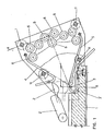
- a mobile contact 2 supported by a contact-holder 2' and a fixed contact 3 supported by a contact-holder 3', which can be extended externally of the envelope up to the connecting terminal of an external conductor.
- the fork of the deionization cell opens its two spred jaws 4 and 5, whose narrower part is in front of contact 2 and 3, in such a way as to lure the entrance of the arc which forms at the moment when mobile contact 2 is opened in respect of the fixed contact 3.
- the arc lays its extremities on the jaws 4 and 5 and is pushed into the fork by the magnetic circuits generated by the arc itself so that the arc is stretched while proceeding along the fork.
- the arc movement is intercepted by subdividing elements made up by spheres 6 positioned in such a way that the mutual distance between contiguous couples of spheres is almost equal.
- the spherical shape of elements 6 is the prefer red one, but the elements can be shaped in whatever different form, provided that their external surface be a curved one, without solution of continuity, for instance an oval or elliptical or any equivalent form, able of facing two convex surfaces between two contiguous elements: the partial arc can then stabilize between the two closest points.
- Figure 1 also shows by dotted lines a possible progression in the arc subdivision. Although elements 6 - spherical or of any other shape-- have been indicated equal in size, they may have different dimensions for instance different diameter or axis, without any negative impact on the invention results.
- elements 6 for the subdivision of the electric arc may be of ferrous material thus providing a magnetic self-centering action by the arc itself and making it unprobable that undesired movements, leading to harmful phenomena, may cause the electric arc coming out of the de ionization cell.
- These elements may be made up of ferrous material coated on the surface so that, beside the self-centering action of the arc, it is possible to obtain a protective action and an increased stability of the arc together with an increased cathodic voltage.
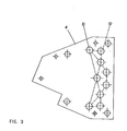
- elements 6 for the arc subdivision are presently arranged closer to the entrance of the fork, so that the path of the arc before its subdivision is remarkably reduced, thus concurrently reducing its extinction time and therefore increasing the breaking power of the switch.
- the elements 6 for the arc subdivision may occupy not only an area between the jaws 4 and 5, but also the entire space comprised between these jaws, so that a labyrinth is offered to the arc where it is submitted to a progressive subdivision, the consequence being a greater quickness in cooling and extinction.
Landscapes
- Arc-Extinguishing Devices That Are Switches (AREA)
- Conductive Materials (AREA)
Priority Applications (1)
| Application Number | Priority Date | Filing Date | Title |
|---|---|---|---|
| AT81830104T ATE15842T1 (de) | 1980-09-24 | 1981-06-25 | Entionisierungskammer zum loeschen des elektrischen lichtbogens. |
Applications Claiming Priority (2)
| Application Number | Priority Date | Filing Date | Title |
|---|---|---|---|
| IT24876/80A IT1133612B (it) | 1980-09-24 | 1980-09-24 | Cella di deionizzazione per l'estinzione dell'arco elettrico |
| IT2487680 | 1980-09-24 |
Publications (3)
| Publication Number | Publication Date |
|---|---|
| EP0048699A2 true EP0048699A2 (de) | 1982-03-31 |
| EP0048699A3 EP0048699A3 (en) | 1982-12-01 |
| EP0048699B1 EP0048699B1 (de) | 1985-09-25 |
Family
ID=11215011
Family Applications (1)
| Application Number | Title | Priority Date | Filing Date |
|---|---|---|---|
| EP81830104A Expired EP0048699B1 (de) | 1980-09-24 | 1981-06-25 | Entionisierungskammer zum Löschen des elektrischen Lichtbogens |
Country Status (6)
| Country | Link |
|---|---|
| EP (1) | EP0048699B1 (de) |
| AR (1) | AR225833A1 (de) |
| AT (1) | ATE15842T1 (de) |
| DE (1) | DE3172425D1 (de) |
| ES (1) | ES503913A0 (de) |
| IT (1) | IT1133612B (de) |
Family Cites Families (2)
| Publication number | Priority date | Publication date | Assignee | Title |
|---|---|---|---|---|
| BE438001A (de) * | 1938-12-02 | |||
| FR873615A (fr) * | 1941-02-27 | 1942-07-15 | Delle Atel Const Electr | Perfectionnements aux boites de soufflage |
-
1980
- 1980-09-24 IT IT24876/80A patent/IT1133612B/it active
-
1981
- 1981-06-25 DE DE8181830104T patent/DE3172425D1/de not_active Expired
- 1981-06-25 AT AT81830104T patent/ATE15842T1/de not_active IP Right Cessation
- 1981-06-25 EP EP81830104A patent/EP0048699B1/de not_active Expired
- 1981-07-13 ES ES503913A patent/ES503913A0/es active Granted
- 1981-09-10 AR AR286724A patent/AR225833A1/es active
Also Published As
| Publication number | Publication date |
|---|---|
| DE3172425D1 (en) | 1985-10-31 |
| ES8204220A1 (es) | 1982-04-16 |
| ES503913A0 (es) | 1982-04-16 |
| AR225833A1 (es) | 1982-04-30 |
| ATE15842T1 (de) | 1985-10-15 |
| IT1133612B (it) | 1986-07-09 |
| EP0048699B1 (de) | 1985-09-25 |
| EP0048699A3 (en) | 1982-12-01 |
| IT8024876A0 (it) | 1980-09-24 |
Similar Documents
| Publication | Publication Date | Title |
|---|---|---|
| JP6444103B2 (ja) | 強磁性側面部材上の小型永久磁石と一群のアーク分離板とを備えた双方向直流電気スイッチング装置 | |
| CA3040399C (en) | Electrical interruption device | |
| CN210167287U (zh) | 双向开关触点装置 | |
| US4876424A (en) | Barrier with a venting scheme for a circuit breaker | |
| US2249499A (en) | Electric circuit interrupter | |
| EP0048699A2 (de) | Entionisierungskammer zum Löschen des elektrischen Lichtbogens | |
| US4491705A (en) | Electrical switch | |
| US4011425A (en) | Arc chute extension for increased interruption rating | |
| EP3772076A1 (de) | Vorrichtung zur tür- und phasentrennung in leistungsschaltern mit formgehäuse | |
| ES8404563A1 (es) | Mejoras en ruptores de circuito limitadores de corriente. | |
| US2761933A (en) | Device for breaking electric circuits | |
| US2387033A (en) | Arc extinguishing device | |
| US3147358A (en) | Magnetic blowout contact switch | |
| US2729723A (en) | Alternating-current circuit interrupters | |
| RU214912U1 (ru) | Магнитный контактор | |
| GB1158351A (en) | Electrical Circuit Interrupters. | |
| Browne | Extinction of short AC. arcs | |
| GB2169450A (en) | A leakage current protection circuit breaker | |
| CN218004673U (zh) | 一种开关的灭弧室 | |
| US6011678A (en) | Electrical device with double AC breaking contacts | |
| SU1339683A1 (ru) | Дугогасительна камера с деионной решеткой | |
| EP0061006B1 (de) | Vorrichtung zum Einschränken eines Lichtbogens in einem Schalter | |
| SU974451A1 (ru) | Автоматический выключатель | |
| SU851525A1 (ru) | Самовосстанавливающийс ограничительТОКА | |
| SU775775A1 (ru) | Контактное устройство вакуумной дугогасительной камеры |
Legal Events
| Date | Code | Title | Description |
|---|---|---|---|
| PUAI | Public reference made under article 153(3) epc to a published international application that has entered the european phase |
Free format text: ORIGINAL CODE: 0009012 |
|
| AK | Designated contracting states |
Designated state(s): AT BE CH DE FR GB LI LU NL SE |
|
| PUAL | Search report despatched |
Free format text: ORIGINAL CODE: 0009013 |
|
| AK | Designated contracting states |
Designated state(s): AT BE CH DE FR GB LI LU NL SE |
|
| RHK1 | Main classification (correction) |
Ipc: H01H 9/36 |
|
| 17P | Request for examination filed |
Effective date: 19830524 |
|
| GRAA | (expected) grant |
Free format text: ORIGINAL CODE: 0009210 |
|
| AK | Designated contracting states |
Designated state(s): AT BE CH DE FR GB LI LU NL SE |
|
| REF | Corresponds to: |
Ref document number: 15842 Country of ref document: AT Date of ref document: 19851015 Kind code of ref document: T |
|
| REF | Corresponds to: |
Ref document number: 3172425 Country of ref document: DE Date of ref document: 19851031 |
|
| ET | Fr: translation filed | ||
| PLBI | Opposition filed |
Free format text: ORIGINAL CODE: 0009260 |
|
| PG25 | Lapsed in a contracting state [announced via postgrant information from national office to epo] |
Ref country code: LU Free format text: LAPSE BECAUSE OF NON-PAYMENT OF DUE FEES Effective date: 19860630 |
|
| 26 | Opposition filed |
Opponent name: SIEMENS AKTIENGESELLSCHAFT, BERLIN UND MUENCHEN Effective date: 19860613 |
|
| NLR1 | Nl: opposition has been filed with the epo |
Opponent name: SIEMENS AKTIENGESELLSCHAFT |
|
| PLBN | Opposition rejected |
Free format text: ORIGINAL CODE: 0009273 |
|
| STAA | Information on the status of an ep patent application or granted ep patent |
Free format text: STATUS: OPPOSITION REJECTED |
|
| 27O | Opposition rejected |
Effective date: 19880331 |
|
| NLR2 | Nl: decision of opposition | ||
| PGFP | Annual fee paid to national office [announced via postgrant information from national office to epo] |
Ref country code: AT Payment date: 19900510 Year of fee payment: 10 |
|
| PGFP | Annual fee paid to national office [announced via postgrant information from national office to epo] |
Ref country code: GB Payment date: 19900515 Year of fee payment: 10 |
|
| PGFP | Annual fee paid to national office [announced via postgrant information from national office to epo] |
Ref country code: BE Payment date: 19900518 Year of fee payment: 10 |
|
| PGFP | Annual fee paid to national office [announced via postgrant information from national office to epo] |
Ref country code: CH Payment date: 19900522 Year of fee payment: 10 |
|
| PGFP | Annual fee paid to national office [announced via postgrant information from national office to epo] |
Ref country code: LU Payment date: 19900523 Year of fee payment: 10 |
|
| PGFP | Annual fee paid to national office [announced via postgrant information from national office to epo] |
Ref country code: DE Payment date: 19900530 Year of fee payment: 10 |
|
| PGFP | Annual fee paid to national office [announced via postgrant information from national office to epo] |
Ref country code: SE Payment date: 19900607 Year of fee payment: 10 |
|
| PGFP | Annual fee paid to national office [announced via postgrant information from national office to epo] |
Ref country code: FR Payment date: 19900629 Year of fee payment: 10 |
|
| PGFP | Annual fee paid to national office [announced via postgrant information from national office to epo] |
Ref country code: NL Payment date: 19900630 Year of fee payment: 10 |
|
| PG25 | Lapsed in a contracting state [announced via postgrant information from national office to epo] |
Ref country code: GB Effective date: 19910625 Ref country code: AT Effective date: 19910625 |
|
| PG25 | Lapsed in a contracting state [announced via postgrant information from national office to epo] |
Ref country code: SE Effective date: 19910626 |
|
| PG25 | Lapsed in a contracting state [announced via postgrant information from national office to epo] |
Ref country code: LI Effective date: 19910630 Ref country code: CH Effective date: 19910630 Ref country code: BE Effective date: 19910630 |
|
| BERE | Be: lapsed |
Owner name: BASSANI TICINO S.P.A. Effective date: 19910630 |
|
| PG25 | Lapsed in a contracting state [announced via postgrant information from national office to epo] |
Ref country code: NL Effective date: 19920101 |
|
| NLV4 | Nl: lapsed or anulled due to non-payment of the annual fee | ||
| GBPC | Gb: european patent ceased through non-payment of renewal fee | ||
| PG25 | Lapsed in a contracting state [announced via postgrant information from national office to epo] |
Ref country code: FR Effective date: 19920228 |
|
| REG | Reference to a national code |
Ref country code: CH Ref legal event code: PL |
|
| PG25 | Lapsed in a contracting state [announced via postgrant information from national office to epo] |
Ref country code: DE Effective date: 19920401 |
|
| REG | Reference to a national code |
Ref country code: FR Ref legal event code: ST |
|
| EUG | Se: european patent has lapsed |
Ref document number: 81830104.6 Effective date: 19920109 |