EP0048647A1 - Electronic adapting circuit for taking in diagnostic information from an electronic control device - Google Patents
Electronic adapting circuit for taking in diagnostic information from an electronic control device Download PDFInfo
- Publication number
- EP0048647A1 EP0048647A1 EP81401339A EP81401339A EP0048647A1 EP 0048647 A1 EP0048647 A1 EP 0048647A1 EP 81401339 A EP81401339 A EP 81401339A EP 81401339 A EP81401339 A EP 81401339A EP 0048647 A1 EP0048647 A1 EP 0048647A1
- Authority
- EP
- European Patent Office
- Prior art keywords
- circuit
- output
- indicator
- microcomputer
- transistor
- Prior art date
- Legal status (The legal status is an assumption and is not a legal conclusion. Google has not performed a legal analysis and makes no representation as to the accuracy of the status listed.)
- Granted
Links
Images
Classifications
-
- B—PERFORMING OPERATIONS; TRANSPORTING
- B60—VEHICLES IN GENERAL
- B60R—VEHICLES, VEHICLE FITTINGS, OR VEHICLE PARTS, NOT OTHERWISE PROVIDED FOR
- B60R16/00—Electric or fluid circuits specially adapted for vehicles and not otherwise provided for; Arrangement of elements of electric or fluid circuits specially adapted for vehicles and not otherwise provided for
- B60R16/02—Electric or fluid circuits specially adapted for vehicles and not otherwise provided for; Arrangement of elements of electric or fluid circuits specially adapted for vehicles and not otherwise provided for electric constitutive elements
- B60R16/023—Electric or fluid circuits specially adapted for vehicles and not otherwise provided for; Arrangement of elements of electric or fluid circuits specially adapted for vehicles and not otherwise provided for electric constitutive elements for transmission of signals between vehicle parts or subsystems
-
- G—PHYSICS
- G06—COMPUTING; CALCULATING OR COUNTING
- G06F—ELECTRIC DIGITAL DATA PROCESSING
- G06F11/00—Error detection; Error correction; Monitoring
- G06F11/07—Responding to the occurrence of a fault, e.g. fault tolerance
- G06F11/0703—Error or fault processing not based on redundancy, i.e. by taking additional measures to deal with the error or fault not making use of redundancy in operation, in hardware, or in data representation
- G06F11/0751—Error or fault detection not based on redundancy
- G06F11/0754—Error or fault detection not based on redundancy by exceeding limits
- G06F11/0757—Error or fault detection not based on redundancy by exceeding limits by exceeding a time limit, i.e. time-out, e.g. watchdogs
-
- G—PHYSICS
- G06—COMPUTING; CALCULATING OR COUNTING
- G06F—ELECTRIC DIGITAL DATA PROCESSING
- G06F11/00—Error detection; Error correction; Monitoring
- G06F11/30—Monitoring
- G06F11/32—Monitoring with visual or acoustical indication of the functioning of the machine
- G06F11/324—Display of status information
- G06F11/325—Display of status information by lamps or LED's
-
- G—PHYSICS
- G06—COMPUTING; CALCULATING OR COUNTING
- G06F—ELECTRIC DIGITAL DATA PROCESSING
- G06F11/00—Error detection; Error correction; Monitoring
- G06F11/30—Monitoring
- G06F11/32—Monitoring with visual or acoustical indication of the functioning of the machine
- G06F11/321—Display for diagnostics, e.g. diagnostic result display, self-test user interface
Definitions
- the present invention relates to an electronic adapter device for a diagnostic socket to the information supplied by an electronic control circuit and more particularly to the connection to the control wire of a diagnostic light of an electronic control circuit.
- the present invention makes it possible to avoid these drawbacks.
- the electronic adapter device of a diagnostic socket to the information provided by an electronic control circuit which is of the type comprising a microcomputer, a circuit for monitoring the operating state of the microcomputer connected directly to a first pin of output of said microcomputer and an indicator light of the electronic control circuit and of its input and output peripherals, is remarkable in that said indicator light is connected to a second output pin of said microcomputer by means of a circuit d ignition and protection and in that the diagnostic information is available in series on the input terminal of said indicator.
- said electronic adapter device comprises a first transistor connected: by its base on the one hand to the output of said monitoring circuit, on the other hand to said second output pin, by its emitter to ground and by its collector to said sight glass by means of a first resistance supplying a pilot current to a DARLINGTON circuit in parallel by its outputs on said sight glass
- the output of said monitoring circuit is connected to the base of said first transistor via a second resistor supplying the control current of said transistor and a protection diode.
- the emitter of the DARLINGTON circuit is grounded via a third resistor and a second transistor is connected: by its collector on the one hand to the collector of the first transistor, on the other hand at the base of the DARLINGTON circuit, by its ground transmitter and by its base at the point common to the DARLINGTON circuit transmitter and to said third resistor.
- a capacitor ensuring the stability of the output of the adapter circuit is connected between the collectors of said second transistor and of said DARLINGTON circuit.
- a microcomputer 10 is connected by its output P 16 to a monostable 11 connected by its output Q to the base of a first transistor 16 via the series connection of a resistor 14 and a protection diode 15.
- the width of the pulse supplied by the monostable 11 is adjusted by means of a resistor 12 and a capacitor 13 as is known to the technician.
- a second output P 02 of the microcomputer 10 is also connected to the base of the first transistor 16 which constitutes the input element of an ignition and protection circuit 30 which is connected by its output 21 to the input terminal an indicator 22 arranged for example on the dashboard of a motor vehicle and the other terminal 23 of which is put at the voltage + 12 V of the vehicle battery.
- the ignition and protection circuit 30 further comprises a second transistor 18 and a power DARLINGTON 19.
- the emitters of the two transistors 16 and 18 are at ground at 25 while the emitter of the DARLINGTON is at ground 25 by via a resistor 240
- the transistor 18 and said resistor 24, of low ohmic value make it possible to fix the maximum current flowing in the indicator 22. Therefore the output transistor 19 is protected against the application of at point 21 + 12 Volts / whatever its state: saturated or blocked.
- the combination of the transistor 18 and the resistor 24 in its base represents a current limitation which is fixed taking into account the characteristics of the indicator 22 and the possible heat dissipation on the transistor 18 in the event of imposition of the most battery at the point 21 when the transistor 18 is saturated.
- the collector of the first transistor 16 is connected on the one hand to the input terminal 21 of the indicator light 22 via a resistor 17 which conditions the supply of a basic current, therefore of piloting to the DARLINGTON 19, on the other hand to the collector of the DARLINGTON 19 via a capacitor 20 which ensures the stability of the output, on the other hand also to the base of DARLINGTON 19 and finally to the collector of second transistor 180
- the collector of transistor 18 is therefore connected on the one hand to resistor 17 and to capacitor 20, on the other hand to the base of DARLINGTON 19 and the collector of DARLINGTON 19 is connected to point 21 which is both the output point of circuit 30 and the input terminal of indicator light 22 as already mentioned.
- the output P02 is in the high state in this case.
- the microcomputer 10 is such that its pin P 02 has no "resistance” connected to + 5 Volts, it is an "open collector". In this case, the transistor 16 is therefore saturated, which imposes the blocking of the DARLINGTON 19 because the voltage on its base no longer allows its conduction.
- the capacitor 20 ensures the unconditional stability of the current regulation device constituted by the transistor 18 and the resistor 24.
- the indicator light 22 can be turned on or off according to the command desired by the central unit 10 or, depending on the state of the monostable 11.
- the state of the monostable 11 is also a priority.
- the object of the present invention is to output in the form of serial messages the information necessary for the development or after-sales services on the output 21 for controlling the indicator light 22.
- the information is output in the form illustrated in FIG. 2. This information is output at point 21 whether the indicator 22 is on or off.
- N.H. means high level and NoB. means basic level
- the light 22 is then returned to the state, on or off, that it had before the output of this information.
- the central unit 10 controls the output of this diagnosis with a recurrence sufficiently slow for the indicator to appear to remain on or off, according to the statistical state which is given to it.
- the indicator 22 is lit as indicated previously, but there is no longer any output of the serial information at point 21 because the transistor 16 is blocked. Similarly, if the 5-volt supply to the microcomputer 10 disappears, the indicator 22 lights up as explained above and the serial message also disappears. For this, the + 12 V of the indicator 22 must of course remain present.
- the indicator 22 can also be replaced by a light-emitting diode LED in series with a resistor.
- the diagnostic reading means is an optical reader placed opposite the light-emitting diode. This optical solution eliminates the obligation to physically connect to the box.
- the indicator 22 can also be replaced by any sensor or actuator such as: relay, lamp, light-emitting diodes, electromagnets without this list being in any way limiting.
Abstract
Le circuit de commande électronique est du type comportant un micro-calculateur (10), un circuit de surveillance (11) de l'état de fonctionnement du microcalculateur (10) connecté directement à une première broche (P16) de sortie de ce dernier, et un voyant (22) du circuit de commande et de ses périphériques d'entrée et de sortie, remarquable en ce que ledit voyant (22) est connecté à une seconde broche de sortie (P02) dudit microcalculateur (10) par l'intermédiaire d'un circuit d'allumage et de protection (30) et en ce que les informations de diagnostic sont disponibles en série sur la borne d'entrée (21) dudit voyant (22) qui est également la sortie dudit circuit d'allumage et de protection (30). Industrie automobile.The electronic control circuit is of the type comprising a microcomputer (10), a monitoring circuit (11) of the operating state of the microcomputer (10) connected directly to a first output pin (P16) of the latter, and an indicator light (22) of the control circuit and of its input and output peripherals, remarkable in that said indicator light (22) is connected to a second output pin (P02) of said microcomputer (10) via an ignition and protection circuit (30) and in that the diagnostic information is available in series on the input terminal (21) of said indicator (22) which is also the output of said ignition circuit and protection (30). Automobile industry.
Description
La présente invention est relative à un dispositif adaptateur électronique d'une prise diagnostic aux informations fournies par un circuit de commande électronique et plus particulièrement à la connexion sur le fil de commande d'un voyant du-diagnostic d'un circuit de commande électronique.The present invention relates to an electronic adapter device for a diagnostic socket to the information supplied by an electronic control circuit and more particularly to the connection to the control wire of a diagnostic light of an electronic control circuit.
Dans le domaine de l'électronique automobile, quand on utilise un circuit de commande électronique faisant usage notamment d'un microcalculateur, il est courant d'associer une prise diagnostic aux circuits de sortie en vue d'obtenir d'une manière commode les informations nécessaires au diagnostic du système. L'allumage d'un voyant associé au tableau de bord avertit le conducteur qu'un défaut s'est produit dans le circuit électronique de commande ou dans ses périphériques d'entrée ou de sortie et l'incite à se rendre chez son réparateuroIn the field of automotive electronics, when using an electronic control circuit making use in particular of a microcomputer, it is common to associate a diagnostic socket with the output circuits in order to obtain information in a convenient manner necessary for system diagnosis. The lighting of an indicator associated with the dashboard alerts the driver that a fault has occurred in the electronic control circuit or in its input or output devices and encourages him to go to his repairer.
La réalisation d'une prise diagnostic telle qu'elle est conçue actuellement conduit à un dispositif complexe et onéreux du fait du grand nombre de conducteurs qui y aboutissent, des problèmes de protection liés à chacun de ces conducteurs qui conduisent à la réalisation d'interfaces complexes et coûteuses et des problèmes d'étanchéité.The realization of a diagnostic socket as it is currently designed leads to a complex and expensive device because of the large number of conductors which lead to it, protection problems linked to each of these conductors which lead to the production of interfaces complex and expensive and sealing problems.
La présente invention permet d'éviter ces inconvénients.The present invention makes it possible to avoid these drawbacks.
Suivant la présente invention, le dispositif adaptateur électronique d'une prise diagnostic aux informations fournies par un circuit de commande électronique qui est du type comportant un microcalculateur, un circuit de surveillance de l'état de fonctionnement du microcalculateur connecté directement à une première broche de sortie dudit microcalculateur et un voyant du circuit de commande électronique et de ses périphériques d'entrée et de sortie, est remarquable en ce que ledit voyant est connecté à une seconde broche de sortie dudit micro- calculateur par l'intermédiaire d'un circuit d'allumage et de protection et en ce que les informations de diagnostic sont disponibles en série sur la borne d'entrée dudit voyant.According to the present invention, the electronic adapter device of a diagnostic socket to the information provided by an electronic control circuit which is of the type comprising a microcomputer, a circuit for monitoring the operating state of the microcomputer connected directly to a first pin of output of said microcomputer and an indicator light of the electronic control circuit and of its input and output peripherals, is remarkable in that said indicator light is connected to a second output pin of said microcomputer by means of a circuit d ignition and protection and in that the diagnostic information is available in series on the input terminal of said indicator.
Suivant une première caractéristique de réalisation ledit dispositif adaptateur électronique comprend un premier transistor connecté : par sa base d'une part à la sortie dudit circuit de surveillance, d'autre part à ladite seconde broche de sortie, par son émetteur à la masse et par son collecteur audit voyant par l'intermédiaire d'une première résistance de fourniture d'un courant de pilotage à un circuit DARLINGTON en parallèle par ses sorties sur ledit voyanteAccording to a first embodiment characteristic, said electronic adapter device comprises a first transistor connected: by its base on the one hand to the output of said monitoring circuit, on the other hand to said second output pin, by its emitter to ground and by its collector to said sight glass by means of a first resistance supplying a pilot current to a DARLINGTON circuit in parallel by its outputs on said sight glass
Avantageusement, la sortie dudit circuit de surveillance est connectée à la base dudit premier transistor par l'intermédiaire d'une seconde résistance fournissant le courant de commande dudit transistor et d'une diode de protection.Advantageously, the output of said monitoring circuit is connected to the base of said first transistor via a second resistor supplying the control current of said transistor and a protection diode.
Suivant une seconde caractéristique de réalisation, l'émetteur du circuit DARLINGTON est à la masse par l'intermédiaire d'une troisième résistance et un second transistor est connecté : par son collecteur d'une part au collecteur du premier transistor, d'autre part à la base du circuit DARLINGTON, par son émetteur à la masse et par sa base au point commun à l'émetteur du circuit DARLINGTON et à ladite troisième résistance.According to a second embodiment characteristic, the emitter of the DARLINGTON circuit is grounded via a third resistor and a second transistor is connected: by its collector on the one hand to the collector of the first transistor, on the other hand at the base of the DARLINGTON circuit, by its ground transmitter and by its base at the point common to the DARLINGTON circuit transmitter and to said third resistor.
Suivant une troisième caractéristique de réalisation, un condensateur assurant la stabilité de la sortie du circuit adaptateur est connecté entre les collecteurs dudit second transistor et dudit circuit DARLINGTON.According to a third embodiment characteristic, a capacitor ensuring the stability of the output of the adapter circuit is connected between the collectors of said second transistor and of said DARLINGTON circuit.
De cette manière, on obtient, sous forme de messages codés, les informations qui permettent aux services après-vente, le contrôle et le dépannage du système et de ses capteurs sans l'adjonction d'un connecteur ni d'une interface aussi particulière que complexe ce qui constitue une économie appréciable.In this way, information is obtained in the form of coded messages which allow after-sales services, control and troubleshooting of the system and its sensors without the addition of a connector or an interface as special as complex which constitutes a significant saving.
D'autres caractéristiques ressortiront de la description qui suit et qui n'est donnée qu'à titre d'exemple . A cet effet on se reportera aux dessins joints dans lesquels :
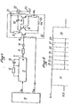
- - la figure 1 est une représentation schématique d'un mode de réalisation du dispositif adaptateur électronique suivant la présente invention ; et,
- - la figure 2 donne un exemple des informations qui sont disponibles sous la forme de messages série sur la sortie de commande du voyant de la figure 1.
- - Figure 1 is a schematic representation of a mode of realization of the electronic adapter device according to the present invention; and,
- FIG. 2 gives an example of the information which is available in the form of serial messages on the command output of the indicator lamp in FIG. 1.
Suivant la représentation de la figure 1, un microcalculateur 10 est connecté par sa sortie P16 à un monostable 11 connecté par sa sortie Q à la base d'un premier transistor 16 par l'intermédiaire de la connexion en série d'une résistance 14 et d'une diode de protection 15. La largeur de l'impulsion fournie par le monostable 11 est réglée au moyen d'une résistance 12 et d'un condensateur 13 comme il est connu du technicien. Une seconde sortie P02 du microcalculateur 10 est connectée également à la base du premier transistor 16 qui constitue l'élément d'entrée d'un circuit 30 d'allumage et de protection qui est connecté par sa sortie 21 à la borne d'entrée d'un voyant 22 disposé par exemple sur le tableau de bord d'un véhicule automobile et dont l'autre borne 23 est mise à la tension + 12 V de la batterie du véhicule.According to the representation of FIG. 1, a
Le circuit 30 d'allumage et de protection comprend en outre un second transistor 18 et un DARLINGTON de puissance 19. Les émetteurs des deux transistors 16 et 18 sont à la masse en 25 tandis que l'émetteur du DARLINGTON est à la masse 25 par l'intermédiaire d'une résistance 240 Le transistor 18 et ladite résistance 24, de faible valeur ohmique permettent de fixer le courant maximum circulant dans le voyant 22. De ce fait le transistor de sortie 19 est protégé contre l'application du au point 21 + 12 Volts/quel que soit son état : saturé ou bloqué. La combinaison du transistor 18 et de la résistance 24 dans sa base représente une limitation en courant que l'on fixe compte tenu des caractéristiques du voyant 22 et de la dissipation thermique possible sur le transistor 18 en cas d'imposition du plus batterie au point 21 quand le transistor 18 est saturé.The ignition and
Le collecteur du premier transistor 16 est relié d'une part à la borne d'entrée 21 du voyant 22 par l'intermédiaire d'une résistance 17 qui conditionne la fourniture d'un courant de base, donc de pilotage au DARLINGTON 19, d'autre part au collecteur du DARLINGTON 19 par l'intermédiaire d'un condensateur 20 qui assure la stabilité de la sortie, d'autre part encore à la base du DARLINGTON 19 et enfin au collecteur du second transistor 180 Le collecteur du transistor 18 est donc relié d'une part à la résistance 17 et au condensateur 20, d'autre part à la base du DARLINGTON 19 et le collecteur du DARLINGTON 19 est connecté au point 21 qui est à la fois le point de sortie du circuit 30 et la borne d'entrée du voyant 22 comme on l'a déjà dit.The collector of the
Le système fonctionne comme suit :
- Le
voyant 22 peut être par exemple le voyant défaut d'un système électronique dont lemicrocalculateur 10 n'est qu'une partie. Levoyant 22 s'allume si lemicrocalculateur 10 détecte une anomalie de fonctionnement d'un des capteurs du système tels que capteur vitesse, capteur de charge, interface électrohydraulique ou si lemonostable 11 vient à se désarmer, d'après le principe du "chien de garde" (watch- dog en anglais) dont le pilotage est effectué périodiquement par les impulsions apparaissant sur la sortie P16 du microcalculateur. S'il n'y a aucun défaut, lemonostable 11 est réarmé. Sa sortie Q est à l'état haut.
- The
indicator 22 can for example be the fault indicator of an electronic system of which themicrocomputer 10 is only a part. Theindicator 22 lights up if themicrocomputer 10 detects an operating anomaly of one of the system sensors such as speed sensor, load sensor, electrohydraulic interface or if the monostable 11 comes to disarm, according to the principle of " watchdog "(watchdog in English) whose piloting is carried out periodically by the pulses appearing on the output P 16 of the microcomputer. If there is no fault, the monostable 11 is reset. Its output Q is high.
De même la sortie P02 est à l'état haut dans ce cas là. Il faut noter que le microcalculateur 10 est tel que sa broche P02 n'a pas de "résistance" connectée au + 5 Volts, c'est un "collecteur ouvert". Dans ce cas là le transistor 16 est donc saturé, ce qui impose le blocage du DARLINGTON 19 car la tension sur sa base ne permet plus sa conduction.Similarly, the output P02 is in the high state in this case. It should be noted that the
Dès qu'un défaut est signalé par le microcalculateur 10, sa broche P02 passe à l'état bas. Le transistor 16 se bloque alors et le DARLINGTON 19 se met à conduire. Le voyant 22 est donc allumé. De même, le voyant 22 est allumé quand le monostable 11 se désarme. En effet, si le microcalculateur 10 ne pilote plus le monostable 11, la sortie Q de ce dernier passe à zéro et quel que soit l'état de la broche P , le transistor 16 se bloque ce qui amène le DARLINGTON 19 à sa conduction au travers d'un courant de base imposé par la résistance 17.As soon as a fault is signaled by the
Le condensateur 20 assure la stabilité inconditionnelle du dispositif de régulation en courant constitué par le transistor 18 et la résistance 24.The
Il garantit de ce fait, lors de la transmission des informations sur le voyant, la pureté des transitions logiques en prohibant toutes les oscillations parasites.It therefore guarantees, during the transmission of information on the LED, the purity of the logical transitions by prohibiting all parasitic oscillations.
On voit donc que l'on peut allumer ou éteindre le voyant 22 selon la commande voulue par l'unité centrale 10 ou, selon l'état du monostable 11.It can therefore be seen that the
L'état du monostable 11 est d'ailleurs prioritaireoThe state of the monostable 11 is also a priority.
Le but de la présente invention est de sortir sous forme de messages série les informations nécessaires à la mise au point ou aux services après-vente sur la sortie 21 de commande du voyant 22.The object of the present invention is to output in the form of serial messages the information necessary for the development or after-sales services on the
Les informations sont sorties sous la forme illustrée à la figure 2. On sort ces informations au point 21 que le voyant 22 soit allumé ou éteint.The information is output in the form illustrated in FIG. 2. This information is output at
Pour cela on éteint le voyant 22 pendant 420µs (intervalle 31) à moins qu'il ne soit déjà éteint. A la figure 2 : N.H. signifie niveau haut et NoB. signifie niveau baseFor this, the
On sort ensuite au rythme de 60µs par information, les données suivantes, dont la succession indiquée ci-après n'est fournie qu'à titre d'exemple non limitatif :
- Intervalle 32 : START : il permet de synchroniser le système de lecture des informations à décoder.
- Intervalle 33 : DEFAUT ELECTRO : au niveau haut, s'il y a un défaut électrovanne détecté par 10 ; au niveau bas dans les autres cas.
- Intervalle 34 : DEFAUT VITESSE : au niveau haut, si un défaut du capteur vitesse est constaté ; au niveau bas dans les autres cas.
- Intervalle 35 : DEFAUT CAPTEUR CHARGE : au niveau haut, si un défaut est constaté dans la mesure de la charge ; au niveau bas dans les autres caso
- Intervalle 36 : FM2 : représente l'état du sélecteur de vitesse.
- Intervalle 37 : FM1 : représente l'état du sélecteur de vitesse.
- Intervalle 38 : RC : indique si la pédale est en position "Kick down" (pied à fond).
- Intervalle 39 : STOP : il permet d'indiquer au système de lecture des informations précédentes la fin de la lecture de ces six informations.
- Interval 32: START: it allows synchronization of the system for reading the information to be decoded.
- Interval 33: ELECTROFAULT: at high level, if there is a solenoid fault detected by 10; low in all other cases.
- Interval 34: SPEED FAULT: at high level, if a speed sensor fault is noted; low in all other cases.
- Interval 35: LOAD SENSOR FAULT: high, if a fault is found in the load measurement; at low level in the other casos
- Interval 36: FM2: represents the state of the speed selector.
- Interval 37: FM1: represents the state of the speed selector.
- Interval 38: RC: indicates if the pedal is in the "Kick down" position.
- Interval 39: STOP: it indicates to the reading system of previous information the end of reading of these six pieces of information.
On remet ensuite le voyant 22 dans l'état, allumé ou éteint, qu'il avait avant la sortie de ces informations. L'unité centrale 10 pilote la sortie de ce diagnostic avec une récurrence suffisamment lente pour que le voyant paraisse rester allumé ou éteint, selon l'état statistique qui lui est donné.The light 22 is then returned to the state, on or off, that it had before the output of this information. The
Il faut donc que la récurrence de sortie du diagnostic soit supérieure à celle perçue par l'oeil, bien inférieure à 50 Hz par exemple.It is therefore necessary that the recurrence of the diagnostic output is greater than that perceived by the eye, much less than 50 Hz for example.
On peut bien entendu augmenter le nombre d'informations à sortir au point 21 et cela à condition de respecter la condition précédente.It is of course possible to increase the number of pieces of information to be output at
On peut aussi commander pendant un temps court, l'allumage du voyant lors de l'initialisation du système, et cela pour vérifier le bon état du voyant. Cette commande de durée limitée est aussi effectuée par le port P02 de l'unité centrale 10.It is also possible to command for a short time, the lighting of the indicator during the initialization of the system, and this to check the good state of the indicator. This limited-time command is also carried out by port P 02 of the
Si le monostable 11 vient à se désarmer du fait d'un défaut de l'unité centrale 10, le voyant 22 est allumé comme indiqué prédédemment, mais il n'y a plus de sortie des informations série au point 21 car le transistor 16 est bloqué. De même si l'alimentation 5 Volts du micro- calculateur 10 vient à disparaître, le voyant 22 s'allume comme expliqué précédemment et le message série disparaît également. Pour cela, le + 12 V du voyant 22 doit bien entendu, rester présent.If the monostable 11 comes to disarm due to a fault in the
Le fait de situer le prélèvement des informations de diagnostic au point 21 qui constitue la borne d'entrée du voyant 22 présente les avantages suivants :
- - il permet d'enlever la prise diagnostic classique très complexe et très onéreuse ;
- - il permet de sortir les informations désirées sur une sortie 21 affectée à une autre utilisation sur laquelle les protections sont déjà effectuées ;
- - il permet de changer l'information fournie au diagnostic uniquement en changeant le programme du microcalculateur, sans toucher au circuit électronique 30 ;
- - il permet d'augmenter le nombre d'informations à sortir sans augmenter le coût du produit ;
- - il permet de diminuer dans d'appréciables proportions le coût global du produit.
- - it makes it possible to remove the very complex and very expensive conventional diagnostic plug;
- - It allows to output the desired information on an
output 21 assigned to another use on which the protections are already made; - - It allows to change the information provided to the diagnosis only by changing the program of the microcomputer, without touching the
electronic circuit 30; - - it increases the number of information to be output without increasing the cost of the product;
- - it allows the overall cost of the product to be reduced in appreciable proportions.
Le voyant 22 peut aussi être remplacé par une diode électroluminescente LED en série avec une résistance. Dans ce cas, le moyen de lecture du diagnostic est un lecteur optique placé en face de la diode électroluminescente. Cette solution optique supprime l'obligation de se connecter physiquement au boitier.The
Le voyant 22 peut encore être remplacé par n'importe quel capteur ou actuateur tels que : relais, lampe, diodes électroluminescentes, électroaimants sans que cette liste ait le moindre caractère limitatif.The
Claims (4)
Applications Claiming Priority (2)
| Application Number | Priority Date | Filing Date | Title |
|---|---|---|---|
| FR8020390 | 1980-09-23 | ||
| FR8020390A FR2490842A1 (en) | 1980-09-23 | 1980-09-23 | ELECTRONIC ADAPTER DEVICE OF A DIAGNOSTIC SOCKET WITH INFORMATION PROVIDED BY AN ELECTRONIC CONTROL CIRCUIT |
Publications (2)
| Publication Number | Publication Date |
|---|---|
| EP0048647A1 true EP0048647A1 (en) | 1982-03-31 |
| EP0048647B1 EP0048647B1 (en) | 1984-10-10 |
Family
ID=9246203
Family Applications (1)
| Application Number | Title | Priority Date | Filing Date |
|---|---|---|---|
| EP81401339A Expired EP0048647B1 (en) | 1980-09-23 | 1981-08-25 | Electronic adapting circuit for taking in diagnostic information from an electronic control device |
Country Status (5)
| Country | Link |
|---|---|
| US (1) | US4399429A (en) |
| EP (1) | EP0048647B1 (en) |
| JP (1) | JPS581253A (en) |
| DE (1) | DE3166621D1 (en) |
| FR (1) | FR2490842A1 (en) |
Cited By (1)
| Publication number | Priority date | Publication date | Assignee | Title |
|---|---|---|---|---|
| FR2555331A1 (en) * | 1983-11-17 | 1985-05-24 | Swf Auto Electric Gmbh | CIRCUIT COMPRISING A MICROCOMPUTER, ESPECIALLY FOR ADJUSTING THE SEAT OF A MOTOR VEHICLE |
Families Citing this family (8)
| Publication number | Priority date | Publication date | Assignee | Title |
|---|---|---|---|---|
| DE3139067C2 (en) * | 1981-10-01 | 1990-10-25 | Bayerische Motoren Werke AG, 8000 München | Electrical device for triggering switching functions in motor vehicles |
| JPS58162875A (en) * | 1982-03-23 | 1983-09-27 | Mitsubishi Electric Corp | Charge displaying and warning device |
| US4567474A (en) * | 1983-06-06 | 1986-01-28 | Temco Products Corporation | Freezer accidental defrost warning device |
| JPS60125711U (en) * | 1984-01-31 | 1985-08-24 | 三菱電機株式会社 | Low-noise air-cooled cooling device |
| JPS60125712U (en) * | 1984-01-31 | 1985-08-24 | 三菱電機株式会社 | Low-noise air-cooled cooling device |
| JPS60125713U (en) * | 1984-01-31 | 1985-08-24 | 三菱電機株式会社 | Low-noise air-cooled cooling device |
| JPS60125710U (en) * | 1984-01-31 | 1985-08-24 | 三菱電機株式会社 | Low-noise air-cooled cooling device |
| CN106374446B (en) * | 2016-08-30 | 2019-03-26 | 德韧干巷汽车系统(上海)有限公司 | Selector circuit used in a kind of SUV vehicle |
Citations (1)
| Publication number | Priority date | Publication date | Assignee | Title |
|---|---|---|---|---|
| FR2343379A1 (en) * | 1976-03-04 | 1977-09-30 | Post Office | DATA PROCESSING EQUIPMENT |
Family Cites Families (4)
| Publication number | Priority date | Publication date | Assignee | Title |
|---|---|---|---|---|
| FR2040973A5 (en) * | 1969-06-18 | 1971-01-22 | Bosch | |
| DE2824190A1 (en) * | 1978-06-02 | 1979-12-06 | Bosch Gmbh Robert | MICRO COMPUTER SYSTEM FOR THE CONTROL OF OPERATING PROCEDURES IN MOTOR VEHICLES, WITH A DIAGNOSTIC DEVICE FOR CHECKING THE VEHICLE |
| US4254410A (en) * | 1979-02-26 | 1981-03-03 | Potter Electric Signal Co. | Pseudo-random pulse line security monitoring system |
| JPS55126841A (en) * | 1979-03-23 | 1980-10-01 | Nissan Motor Co Ltd | Diagnosing method of controller for motorcar |
-
1980
- 1980-09-23 FR FR8020390A patent/FR2490842A1/en active Granted
-
1981
- 1981-08-25 DE DE8181401339T patent/DE3166621D1/en not_active Expired
- 1981-08-25 EP EP81401339A patent/EP0048647B1/en not_active Expired
- 1981-09-22 JP JP56148896A patent/JPS581253A/en active Pending
- 1981-09-23 US US06/304,782 patent/US4399429A/en not_active Expired - Fee Related
Patent Citations (1)
| Publication number | Priority date | Publication date | Assignee | Title |
|---|---|---|---|---|
| FR2343379A1 (en) * | 1976-03-04 | 1977-09-30 | Post Office | DATA PROCESSING EQUIPMENT |
Cited By (2)
| Publication number | Priority date | Publication date | Assignee | Title |
|---|---|---|---|---|
| FR2555331A1 (en) * | 1983-11-17 | 1985-05-24 | Swf Auto Electric Gmbh | CIRCUIT COMPRISING A MICROCOMPUTER, ESPECIALLY FOR ADJUSTING THE SEAT OF A MOTOR VEHICLE |
| GB2149945A (en) * | 1983-11-17 | 1985-06-19 | Swf Auto Electric Gmbh | Circuit arrangement comprising a microcomputer |
Also Published As
| Publication number | Publication date |
|---|---|
| DE3166621D1 (en) | 1984-11-15 |
| EP0048647B1 (en) | 1984-10-10 |
| FR2490842A1 (en) | 1982-03-26 |
| US4399429A (en) | 1983-08-16 |
| JPS581253A (en) | 1983-01-06 |
| FR2490842B1 (en) | 1983-10-14 |
Similar Documents
| Publication | Publication Date | Title |
|---|---|---|
| EP0194915B1 (en) | Controlled electric energy-distributing system in an automotive vehicle | |
| EP0793403A1 (en) | Improvement in LED circuits, especially for vehicles, signalisation lights and control panels | |
| EP0048647B1 (en) | Electronic adapting circuit for taking in diagnostic information from an electronic control device | |
| EP2549836A1 (en) | Circuit for controlling a dual-function lighting or signalling device and corresponding control method | |
| FR2541473A1 (en) | UNIVERSAL INPUT-OUTPUT DEVICE | |
| EP0390698B1 (en) | Defrosting-control system using overvoltage for an electrical windshield of an automotive vehicle | |
| EP0080425B1 (en) | Operating, security and diagnostic device for the electrical system of a vehicle | |
| EP0838361B1 (en) | Device for detecting the presence of a fuel tank cap especially for a motor vehicle | |
| EP2931608B1 (en) | Redundant electric circuit for cutting off the power supply to a piece of equipment | |
| US5587661A (en) | Device for indicating errors in a control line of an electric control units | |
| EP2547554B1 (en) | Switching device for steering column of a vehicle | |
| FR2696252A1 (en) | Electric load control device for vehicle power assisted steering system - supplies HF continuous voltage whilst current input from supply source is sinusoidal and in phase with supply voltage | |
| EP0066513B1 (en) | Control circuit of an electric ventilator motor for cooling an internal-combustion engine | |
| FR2730814A1 (en) | Fault detection device for fusible automobile electrical circuits | |
| EP2725876A1 (en) | Device for electrical connection of a projector | |
| KR100999152B1 (en) | Wiper controll system | |
| EP2037287A1 (en) | Method of detecting a failure in a system for supplying an electrical charge | |
| EP0695667A1 (en) | Warning device with frequency or intensity modulated braking lights for vehicle | |
| FR2976151A1 (en) | Commutation device for auxiliary load of block of LEDs of headlight of car, has auxiliary load whose disconnection/connection is performed when current supplied to LEDs is greater/lower than threshold value, respectively | |
| FR2656105A1 (en) | Device for monitoring the operation of electrical loads of a vehicle | |
| KR0139002Y1 (en) | Back current generated protection device for control facility of automobile | |
| FR2664785A1 (en) | Device for monitoring electrical circuits, intended to detect an anomaly in the operation of such a circuit, and application of the said device to a vehicle lighting and/or signalling system | |
| EP0148064A1 (en) | Electronic control device of the brake lights for vehicles | |
| EP0985578A1 (en) | Control unit of vehicle lights | |
| FR2678785A1 (en) | IMPROVEMENTS IN THE CHARGING CIRCUIT OF THE ACCUMULATOR BATTERY OF A MOTOR VEHICLE. |
Legal Events
| Date | Code | Title | Description |
|---|---|---|---|
| PUAI | Public reference made under article 153(3) epc to a published international application that has entered the european phase |
Free format text: ORIGINAL CODE: 0009012 |
|
| 17P | Request for examination filed |
Effective date: 19810828 |
|
| AK | Designated contracting states |
Designated state(s): BE DE GB IT NL SE |
|
| ITF | It: translation for a ep patent filed |
Owner name: JACOBACCI & PERANI S.P.A. |
|
| GRAA | (expected) grant |
Free format text: ORIGINAL CODE: 0009210 |
|
| AK | Designated contracting states |
Designated state(s): BE DE GB IT NL SE |
|
| REF | Corresponds to: |
Ref document number: 3166621 Country of ref document: DE Date of ref document: 19841115 |
|
| PLBE | No opposition filed within time limit |
Free format text: ORIGINAL CODE: 0009261 |
|
| STAA | Information on the status of an ep patent application or granted ep patent |
Free format text: STATUS: NO OPPOSITION FILED WITHIN TIME LIMIT |
|
| 26N | No opposition filed | ||
| PGFP | Annual fee paid to national office [announced via postgrant information from national office to epo] |
Ref country code: BE Payment date: 19900822 Year of fee payment: 10 |
|
| PGFP | Annual fee paid to national office [announced via postgrant information from national office to epo] |
Ref country code: SE Payment date: 19900827 Year of fee payment: 10 |
|
| PGFP | Annual fee paid to national office [announced via postgrant information from national office to epo] |
Ref country code: NL Payment date: 19900831 Year of fee payment: 10 |
|
| PG25 | Lapsed in a contracting state [announced via postgrant information from national office to epo] |
Ref country code: SE Effective date: 19910826 |
|
| ITTA | It: last paid annual fee | ||
| PG25 | Lapsed in a contracting state [announced via postgrant information from national office to epo] |
Ref country code: BE Effective date: 19910831 |
|
| BERE | Be: lapsed |
Owner name: RENIX ELECTRONIQUE S.A. Effective date: 19910831 |
|
| PG25 | Lapsed in a contracting state [announced via postgrant information from national office to epo] |
Ref country code: NL Effective date: 19920301 |
|
| NLV4 | Nl: lapsed or anulled due to non-payment of the annual fee | ||
| PGFP | Annual fee paid to national office [announced via postgrant information from national office to epo] |
Ref country code: GB Payment date: 19920717 Year of fee payment: 12 |
|
| PGFP | Annual fee paid to national office [announced via postgrant information from national office to epo] |
Ref country code: DE Payment date: 19921023 Year of fee payment: 12 |
|
| PG25 | Lapsed in a contracting state [announced via postgrant information from national office to epo] |
Ref country code: GB Effective date: 19930825 |
|
| GBPC | Gb: european patent ceased through non-payment of renewal fee |
Effective date: 19930825 |
|
| PG25 | Lapsed in a contracting state [announced via postgrant information from national office to epo] |
Ref country code: DE Effective date: 19940503 |
|
| EUG | Se: european patent has lapsed |
Ref document number: 81401339.7 Effective date: 19920306 |