EP0048458A2 - Combined tool holder and spindle for a machine tool, and manufacturing method therefor - Google Patents
Combined tool holder and spindle for a machine tool, and manufacturing method therefor Download PDFInfo
- Publication number
- EP0048458A2 EP0048458A2 EP81107376A EP81107376A EP0048458A2 EP 0048458 A2 EP0048458 A2 EP 0048458A2 EP 81107376 A EP81107376 A EP 81107376A EP 81107376 A EP81107376 A EP 81107376A EP 0048458 A2 EP0048458 A2 EP 0048458A2
- Authority
- EP
- European Patent Office
- Prior art keywords
- chuck
- cups
- tool holder
- spindle
- face
- Prior art date
- Legal status (The legal status is an assumption and is not a legal conclusion. Google has not performed a legal analysis and makes no representation as to the accuracy of the status listed.)
- Withdrawn
Links
Images


Classifications
-
- B—PERFORMING OPERATIONS; TRANSPORTING
- B23—MACHINE TOOLS; METAL-WORKING NOT OTHERWISE PROVIDED FOR
- B23Q—DETAILS, COMPONENTS, OR ACCESSORIES FOR MACHINE TOOLS, e.g. ARRANGEMENTS FOR COPYING OR CONTROLLING; MACHINE TOOLS IN GENERAL CHARACTERISED BY THE CONSTRUCTION OF PARTICULAR DETAILS OR COMPONENTS; COMBINATIONS OR ASSOCIATIONS OF METAL-WORKING MACHINES, NOT DIRECTED TO A PARTICULAR RESULT
- B23Q16/00—Equipment for precise positioning of tool or work into particular locations not otherwise provided for
- B23Q16/02—Indexing equipment
- B23Q16/08—Indexing equipment having means for clamping the relatively movable parts together in the indexed position
-
- B—PERFORMING OPERATIONS; TRANSPORTING
- B23—MACHINE TOOLS; METAL-WORKING NOT OTHERWISE PROVIDED FOR
- B23Q—DETAILS, COMPONENTS, OR ACCESSORIES FOR MACHINE TOOLS, e.g. ARRANGEMENTS FOR COPYING OR CONTROLLING; MACHINE TOOLS IN GENERAL CHARACTERISED BY THE CONSTRUCTION OF PARTICULAR DETAILS OR COMPONENTS; COMBINATIONS OR ASSOCIATIONS OF METAL-WORKING MACHINES, NOT DIRECTED TO A PARTICULAR RESULT
- B23Q3/00—Devices holding, supporting, or positioning work or tools, of a kind normally removable from the machine
- B23Q3/12—Devices holding, supporting, or positioning work or tools, of a kind normally removable from the machine for securing to a spindle in general
Definitions
- the invention relates to an arrangement of tool holder and spindle chuck for machine tools for machining workpieces. It is a combination of tool holder and spindle chuck.
- the tool holder in turn serves to receive a cutting tool that is either mechanically or hydraulically clamped, usually by means of its tool shaft, which is inserted into the tool holder.
- the tool holder (with the tool) is in turn clamped mechanically on the spindle chuck with pliers or magnetically with a magnetic chuck - or also clamped on the table of a machine tool if the tool is to be machined.
- Pairings of this type are used in tool changing devices for automatic tool change in the course of scheduled machining operations, preferably in the machining of workpieces by milling, drilling, spark eroding and the like.
- the change times and processes are controlled by means of paper tape or magnetic tape. Since the machines carry out their program unattended, spark erosion machines e.g. run through even during the night, very high demands are made on the changing device with regard to the adherence to very narrow positional tolerances of the tools on the spindle and the trouble-free change,
- the invention has for its object to find a pair of tool holder and spindle chuck that is self-centering, simple and robust in its structure and therefore maintenance-free, allows easy multiplication (copying) and with the tool change and handover can be performed between a magazine and the spindle with simple, translational and rotational movements.
- This object is achieved according to the invention with an arrangement in which the clamped tool holder rests with its bottom surface on the end face of the spindle chuck at three points and is centered in relation to the end face, at which hemispheres protrude above the end face and these receiving recesses in the floor area.
- Centering is understood here to mean the alignment of the holder in the normal to the face of the chuck (aligned with the spindle axis) and in height and in azimuth (at an angle lying in the face) to the face,
- the self-centering takes place in a sliding movement of the hemispheres on the walls of the recesses receiving them when the holder approaches the chuck.
- a three-point bearing results in a perfect fit in any case, since three points can always be used to lay a plane.
- the three hemispheres and spherical seats are easy to monitor and keep clean.
- the invention thus enables very simple, automatically working tool changing devices with which. Change the balls and their seats only have to be approximately aligned - in contrast to known systems for fixing the position of the tool holder on the chuck, which work with lateral stop surfaces and / or dowel pins.
- the use of hardened steel balls with the smallest diameter tolerances alone is not a guarantee of a finely tolerated position fixation with full interchangeability between tool holders and chucks.
- This also requires a suitable arrangement of the balls and recesses in the surfaces that come into contact with each other.
- the balls are arranged and held in cups which are inserted and cast into recesses in the spindle chuck, while the cups are formed in cups which are inserted and cast into the recess of the tool holder. In this way, an exact position fixation can be achieved on the three contact points during manufacture, which preferably lie on the corners of an equilateral triangle,
- Fig. 1 shows a side view of the quill head 1 of a spark erosion machine.
- a chuck 3 On the sleeve 2 there is a chuck 3, which is centered with a short taper 3.1 and with a reference surface 3.2 (FIG. 3) to a stop bar 2.1 on the sleeve 2 according to height and azimuth (at an angle).
- a holder 4 is seated on the chuck 3, in which the shaft of an electrode (not shown) is received in a known manner (not shown) and held by mechanical or hydraulic clamping.
- Fig. 2 shows the holder 4 with a view of its bottom surface 4.1, in which three conical cups, 5 and three threaded blind holes 4.2 are incorporated in two circles concentric to the holder axis Z-Z at central angles of 120 degrees.
- Fig. 3 shows the chuck 3 with its end face 3.3, from which three steel balls 7 protrude as hemispheres on a circle concentric to the chuck axis Z-Z.
- the 'chuck is a magnetic chuck with an electromagnet 8, the circuit of which is led out to sliding contacts 8.1. You can also see the reference surface ..3.2 to the stop bar 2.1 on the. Quill (Fig. 1) and the short cone 3.1.
- Fig. 4 shows another chuck 9, with which a holder 4 is mechanically clamped, by means of three screws 9a, which are screwed through the holes 9.4 into the threaded blind holes 4.2 of the holder.
- the centering balls 7 protrude again from the end face 9.3 as hemispheres.
- This chuck 9 can in turn be picked up by a quill 2 with its short taper 9.1 and the reference surface 9.2.
- an electrode it is preferably clamped in a corresponding clamping device on the table of a machine tool.
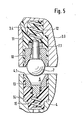
- a preferred embodiment of the three-point centering of an electrode (tool) holder 4 on a chuck 3 or 9 is shown in longitudinal section in the arrangement in FIG. 1 and in the constructive embodiment on an enlarged scale in FIG. 5.
- the balls 7 belonging to the chuck 3 or 9 are arranged in cups 10 and held by means of bolts 7.1 which are cast in and which are cast into recesses 11.
- a compression spring 12 is arranged between the bottoms of bowl 10 and recess 11.
- the casting compound preferably a casting resin
- the bowl 10 has a conical receptacle for the ball 7, on which it rests on a circle.
- the cups 5 are worked out as seats for the balls 7 protruding as hemispheres in cups 13, which are cast into recesses 14.
- a compression spring 15 is again arranged between the bottoms of the bowl 13 and the recess 14.
- the potting compound has been filled through a filling opening 4.3.
- An essential component is a teaching chuck 20 (FIG. 6), the body of which - shaped in the example as a cylinder section - has two plane-parallel end faces 20.1, 20.2 and again a reference face 20.3 according to the dimension of the reference. boundary surfaces 3.2 or 9.2 on the chucks 3 or 9 or according to the distance dimension of the stop bar 2.1 on the sleeve 2 (Fig. 1).
- the end face 20.1 three conical cups 5 are precisely incorporated as a master for the cups 5 in the holders 4.
- the body opens through axially parallel holes 20.4.
- the procedure for producing a holder 4 is similar, except that 20 balls 7 with bolts 7.1 are inserted into the holes 20.4 beforehand in the wells 5 of the teaching chuck. These balls protrude from the end face 20.1 as hemispheres.
- the teaching chuck is placed on a holder 4 and with this by means of the centering surfaces 4.5, 20.5 in of the above-mentioned device are exactly centered on one another, the cups 13, which can move with play in the recesses 14, adjust precisely to the balls 5 under the pressure of the springs i5. They are held in their position by a cast resin filled in at 4.3 after it has solidified in the position they are in.
- any number of holders and chucks can be produced in this way. It can be seen that after tensioning a holder on the chuck, the balls sit in their cups 5 without pressure. Axial clamping pressures are taken up between the end face 3.3 or 9.3 of a chuck 3 or 9 and the bottom face 4.1 of a holder 4. However, there is also the possibility, if necessary, of resetting the contact surfaces of the feed and holder after the casting compound has solidified by grinding if the cups 10, 13 are made of a correspondingly hard material.
- the embodiment of the invention shown as an example can be modified in details, in particular what the application of the contact pressure of the balls or cups during the clamping with the teaching chuck by different types of springs and the fixing of the bowls in their recesses, e.g. B. by means of solder rings.
- the design of the teaching chuck 20 and the means for centering with the duplicates, which are not essential for the invention, are not limited to the example of FIG. 6.
- FIG. 7 shows an alternative embodiment of the invention, in which each ball 7 is anchored in the associated bowl 10 in a particularly simple manner.
- the ball 7 is provided with an axial bore 7.3 and the associated bowl 10 has a threaded blind hole 10.1.
- a bolt 7.2 is inserted into the bore 7.3 and screwed into the threaded blind hole 10.1 and anchored there in a manner that is not shown.
- the execution 'form according to Figure 5 of the invention is the ball 7 on to a peripheral circuit in the receiving cone of the cup 10.3 10th
Abstract
Description
Die Erfindung betrifft eine Anordnung aus Werkzeughalter und Spindel-Spannfutter für Werkzeugmaschinen zur spanabhebenden Bearbeitung von Werkstücken. Es handelt sich also um eine Paarung aus Werkzeughalter und Spindel-Spannfutter. Der Werkzeughalter dient seinerseits zur Aufnahme eines spanabhebenden Werkzeuges, das entweder mechanisch oder hydraulisch gespannt wird, gewöhnlich mittels seines Werkzeugschaftes, der in den Werkzeughalter eingeführt wird. Der Werkzeughalter (mit dem Werkzeug) wird wiederum am Spindel-Spannfutter mechanisch mit Zangen oder magnetisch mit einem Magnetspannfutter gespannt - oder auch auf dem Tisch einer Werkzeugmaschine aufgespannt, wenn das Werkzeug bearbeitet werden soll.The invention relates to an arrangement of tool holder and spindle chuck for machine tools for machining workpieces. It is a combination of tool holder and spindle chuck. The tool holder in turn serves to receive a cutting tool that is either mechanically or hydraulically clamped, usually by means of its tool shaft, which is inserted into the tool holder. The tool holder (with the tool) is in turn clamped mechanically on the spindle chuck with pliers or magnetically with a magnetic chuck - or also clamped on the table of a machine tool if the tool is to be machined.
Paarungen dieser Art dienen in Werkzeugwechseleinrichtungen dem automatischen Werkzeugwechsel im Verlauß planmäßiger Berabeitungsvorgänge, vorzugsweise bei der spanabhebenden 'Bearbeitung von Werkstücken durch Fräsen, Bohren, Funkenerodieren u. dgl. Die Wechselzeiten und -vorgänge werden mittels Lochstreifen oder Magnetband gesteuert. Da die Maschinen ihr Programm unbeaufsichtigt ereledigen, Funkenerodiermaschinen z.B. auch während der Nacht durchlaufen, werden bezüglich der Einhaltung sehr enger Lagetoleranzen der Werkzeuge an der Spindel und des störungsfreien Wechsels sehr hohe Anforderungen an die Wechseleinrichtung gestellt,Pairings of this type are used in tool changing devices for automatic tool change in the course of scheduled machining operations, preferably in the machining of workpieces by milling, drilling, spark eroding and the like. The change times and processes are controlled by means of paper tape or magnetic tape. Since the machines carry out their program unattended, spark erosion machines e.g. run through even during the night, very high demands are made on the changing device with regard to the adherence to very narrow positional tolerances of the tools on the spindle and the trouble-free change,
Der Erfindung liegt die Aufgabe zugrunde, eine Paarung aus Werkzeughalter und Spindel-Spannfutter zu finden, die selbstzentrierend, einfach und robust in ihrem Aufbau und daher wartungsfrei ist, ein einfaches Vervielfachen (kopieren) ermöglicht und mit der Werkzeugwechsel und -übergabe zwischen einem Magazin und der Spindel mit einfachen, translatorischen und Rotationsbewegungen ausgeführt werden können.The invention has for its object to find a pair of tool holder and spindle chuck that is self-centering, simple and robust in its structure and therefore maintenance-free, allows easy multiplication (copying) and with the tool change and handover can be performed between a magazine and the spindle with simple, translational and rotational movements.
Diese Aufgabe wird erfindungsgemäß mit einer Anordnung gelöst, bei der der gespannte Werkzeughalter mit seiner Bodenflache an der Stirnfläche des Spindel-Spannfutters an drei Punkten aufliegt und, bezogen auf die Stirnfläche, zentriert ist, an denen Halbkugeln über die Stirnfläche vorstehen und diese aufnehmende Vertiefungen in der Bodenfläche liegen. Unter "zentrieren" wird hier das Ausrichten des Halters in der Normalen zur Stirnfläche des Futters (fluchtend mit der Spindelachse) sowie in der Höhe und im Azimut (im in der.Fläche liegenden Winkel) zur Stirnfläche verstanden,This object is achieved according to the invention with an arrangement in which the clamped tool holder rests with its bottom surface on the end face of the spindle chuck at three points and is centered in relation to the end face, at which hemispheres protrude above the end face and these receiving recesses in the floor area. "Centering" is understood here to mean the alignment of the holder in the normal to the face of the chuck (aligned with the spindle axis) and in height and in azimuth (at an angle lying in the face) to the face,
Die Selbstzentrierung findet in einer Gleitbewegung der Halbkugeln an den Wänden der sie aufnehmenden Vertiefungen bei der Annäherung des Halters an das Spannfutter statt. Eine Dreipunktlagerung ergibt bekanntlich in jedem Falle einen einwandfreien Sitz, da durch drei Punkte immer eine Ebene gelegt werden kann. Die drei Halbkugeln und Kugelsitze lassen sich auf einfache Weise überwachen und sauberhalten.The self-centering takes place in a sliding movement of the hemispheres on the walls of the recesses receiving them when the holder approaches the chuck. As is well known, a three-point bearing results in a perfect fit in any case, since three points can always be used to lay a plane. The three hemispheres and spherical seats are easy to monitor and keep clean.
Die Erfindung ermöglicht also sehr einfache, automatisch arbeitende Werkzeugwechselvorrichtungen, mit denen beim . Wechsel die Kugeln und ihre Sitze nur näherungsweise aufeinander ausgerichtet sein müssen - im Gegensatz zu bekannten Systemen zur Lagefixierung des Werkzeughalters am Spannfutter, die mit seitlichen Anschlagflächen und/oder Passstiften arbeiten.The invention thus enables very simple, automatically working tool changing devices with which. Change the balls and their seats only have to be approximately aligned - in contrast to known systems for fixing the position of the tool holder on the chuck, which work with lateral stop surfaces and / or dowel pins.
Wenn der Halter sitzt und gespannt wird, kann zugleich eine drehschlüssige Verbindung hergestellt werden, mit der ein für die spanabhebende Arbeit des jeweiligen Werkzeuges benötigtes.Drehmoment von der Spindel auf das Werkzeug übertragen werden kann. Bei der Verwendung der Anordnung an Funkenerodiermaschinen mit drehender Pinole reicht die Lagerun der drei Halbkugeln in ihren Sitzen in Verbindung z.B. mit einem Magnetspannfutter bereits aus.When the holder is seated and clamped, a rotational connection can be made at the same time, with which a torque required for the cutting work of the respective tool can be transferred from the spindle to the tool. When using the arrangement on spark erosion machines with rotating quill, the position of the three hemispheres in their seats in connection with e.g. with a magnetic chuck.
Die Verwendung von Stahlkugeln, wie sie in Präzisionskugellagern verwendet werden, die zur Hälfte in die Stirnfläche des Spannfutters eingelassen sind,, während in die Hodenfläche des Halters konische Becher als Aufnahmen für die zentrierenden Halbkugeln eingelassen sind, ermöglicht eine einfache Fertigung mit hoher Lagepräzision, wie sie insbesondere bei Funkenerodiermaschinen für den Elektrodenwechsel verlangt wird.The use of steel balls, such as those used in precision ball bearings, half of which are embedded in the end face of the chuck, while conical cups are inserted in the testicular surface of the holder as receptacles for the centering hemispheres, enables simple manufacture with high positional precision, such as it is particularly required for spark erosion machines for changing electrodes.
Die Verwendung gehärteter Stahlkugeln mit kleinsten Durchmessertoleranzen allein ist aber noch keine Gewähr für eine feinsttolerierte Lagefixierung bei voller Austauschbarkeit zwischen Werkzeughaltern und Spannfuttern, Dafür ist auch eine passgerechte Anordnung der Kugeln und Vertiefungen in den miteinander in Kontakt kommenden Flächen erforderlich. Hierfür sind in einer bevorzugten Ausführungsform der Erfindung die Kugeln in Näpfen angeordnet und gehalten, die in Ausnehmungen im Spindel-Spannfutter eingeschoben und eingegossen sind, während die Becher in Näpfen ausgeformt sind, die in Ausnehmung des Werkzeughalters eingeschoben und eingegossen sind. Auf diese Weise läßt sich bei der Herstellung eine exakte Lagefixierung auf die drei Kontaktpunkte erreichen, die vorzugsweise auf den Ecken eines gleichseitigen Dreiecks liegen,However, the use of hardened steel balls with the smallest diameter tolerances alone is not a guarantee of a finely tolerated position fixation with full interchangeability between tool holders and chucks. This also requires a suitable arrangement of the balls and recesses in the surfaces that come into contact with each other. For this purpose, in a preferred embodiment of the invention, the balls are arranged and held in cups which are inserted and cast into recesses in the spindle chuck, while the cups are formed in cups which are inserted and cast into the recess of the tool holder. In this way, an exact position fixation can be achieved on the three contact points during manufacture, which preferably lie on the corners of an equilateral triangle,
Die Herstellung von Serien nach einem Kopierverfahren wird in überraschend einfacher Weise erfindungsgemäß dadurch ermöglicht, daß
- ein Lehrfutter mit zwei planparallelen Flächen hergestellt wird, in dessen eine Fläche an den vorgegebenen drei Punkten becherförmige Aufnahmen für Kugeln derart, daß diese als Halbkugeln über die Fläche vorstehen, eingearbeitet werden;
- daß ein Spannfutter in der Weise hergestellt wird, daß in drei vorbereitete Ausnehmungen drei Druckfedern und drei Näpfe mit je einer Kugel eingeschoben werden,
- und daß das vorbereitete Futter mit dem Lehrfutter deckungsgleich zusammengefügt und unter einen Druck gesetzt wird, der den Gegendruck der Druckfedern überwindet, worauf die Näpfe in der Lage, in der sie sich eingestellt haben, mit einem erstarrungsfähigen flüssigen Werkstoff, z.B. Gießharz, eingegossen werden;
- daß ein Werkzeughalter in der Weise hergestellt wird, daß in drei vorbereitete Ausnehmungen drei Druckfedern und drei Näpfe eingeschoben werden,
- und daß der vorbereitete Halter mit dem Lehrfutter in dessen Aufnahmen Kugeln eingesetzt worden sind, deckungsgleich zusammengefügt und unter einen Druck gesetzt wird, der den Gegendruck der Druckfedern überwindet, worauf die Näpfe in der Lage, in der sie sich eingestellt haben, mit einem erstarrungsfähigen flüssigen Werkstoff, z.B. Gießharz, eingegossen werden,
- a teaching chuck with two plane-parallel surfaces is produced, in one surface of which cup-shaped receptacles for balls are incorporated at the predetermined three points in such a way that they protrude as hemispheres over the surface;
- that a chuck is produced in such a way that three compression springs and three cups, each with a ball, are inserted into three prepared recesses,
- and that the prepared feed is congruent with the teaching feed and is put under a pressure which overcomes the counter pressure of the compression springs, whereupon the bowls are poured in with a solidified liquid material, eg casting resin, in the position in which they have set up;
- that a tool holder is manufactured in such a way that three compression springs and three cups are inserted into three prepared recesses,
- and that the prepared holder with the teaching feed balls have been inserted in the receptacles, congruently put together and placed under a pressure which overcomes the counter pressure of the compression springs, whereupon the bowls are in the position in which they have set themselves with a solidified liquid Material, eg cast resin, is poured in,
Gegebenenfalls werden die Stirnflächen der Futter bzw. die Bodenflächen der Halter nach dem Erstarren der Vergußmasse und Abheben von dem Lehrfutter um einige Zehntel mm abgeschliffen. Anordnung und Kopierverfahren nach der Erfindung werden im folgenden anhand einer Zeichnung näher erläutert. In dieser zeigen
- Fig. 1 eine Anordnung aus Elektrodenhalter und Spannfutter an der Pinole einer Funkenerodiermaschine
und dazu jeweils in Draufsicht und (Teil-) Längsschnitt
- Fig. 2 einen Elektrodenhalter,
- Fig. 3 ein Magnetspannfutter,
- Fig. 4 ein mechanisches Spannfutter;
- Fig. 5 eine Einzelheit X aus Fig. 1 in vergrößertem Maßstab;
- Fig. 6 ein Lehrfutter zur Herstellung der Teile im Kopierverfahren.
- Fig. 7 eine schematische Darstellung einer weiteren bevorzugten Ausführungsform der Erfindung.
- Fig. 1 shows an arrangement of electrode holder and chuck on the quill of a spark erosion machine
and in each case in top view and (partial) longitudinal section
- 2 an electrode holder,
- 3 shows a magnetic chuck,
- 4 shows a mechanical chuck;
- FIG. 5 shows a detail X from FIG. 1 on an enlarged scale;
- Fig. 6 is a teaching feed for the production of parts in the copying process.
- Fig. 7 is a schematic representation of a further preferred embodiment of the invention.
Fig. 1 zeigt in Seitenansicht den Pinolenkopf 1 einer Funkenerodiermaschine. An der Pinole 2 sitzt ein Spannfutter 3, das mit einem Kurzkegel 3.1 und mit einer Referenzfläche 3.2 (Fig. 3) zu einer Anschlagleiste 2.1 an der Pinole 2 nach Höhe und Azimut (im Winkel) zentriert ist. An dem Spannfutter 3 sitzt ein Halter 4, in dem in nicht dargestellter, bekannter Weise der Schaft einer(nicht dargestellten) Elektrode aufgenommen und durch mechanisches oder hydraulisches Spannen gehalten wird.Fig. 1 shows a side view of the quill head 1 of a spark erosion machine. On the sleeve 2 there is a
Im Falle einer Werkzeugmaschine für mechanische spanabhebende Bearbeitung (z.B. Bohr- oder Fräsmaschine) würde es sich um den Spindelkopf mit der Spindel und den Werkzeughalter für das Bearbeitungswerkzeug handeln. Die Justierung bzw..Zentrierung des Futters mittels seit- licher Referenzflächen ist von bekannter Art und beibehalten, weil ein Spannfutter nur selten und dann von Hand gewechselt wird.In the case of a machine tool for mechanical machining (for example a drilling or milling machine), it would be the spindle head with the spindle and the tool holder for the machining tool. The Adjustment or centering of the chuck by means of lateral reference surfaces is of a known type and is maintained because a chuck is changed only rarely and then by hand.
Fig. 2 zeigt den Halter 4 mit Blick auf seine Bodenfläche 4.1, in die auf zwei zur Halterachse Z- Z konzentrischen Kreisen unter Zentriwinkeln von 120 Grad drei konische Becher,5 eingelassen und drei Gewinde-Sacklöcher 4.2 eingearbeitet sind.Fig. 2 shows the holder 4 with a view of its bottom surface 4.1, in which three conical cups, 5 and three threaded blind holes 4.2 are incorporated in two circles concentric to the holder axis Z-Z at central angles of 120 degrees.
Fig. 3 zeigt das Spannfutter 3 mit seiner Stirnfläche 3.3, aus der auf einem zur Futterachse Z- Z konzentrischen Kreis drei Stahlkugeln 7 als Halbkugeln hervorstehen. Das' Spannfutter ist ein Magnetspannfutter mit einem Elektromagneten 8, dessen Stromkreis an Schleifkontakte 8.1 herausgeführt ist. Man erkennt ferner die Referenzfläche ..3.2 zur Anschlagleiste 2.1 an der. Pinole (Fig. 1) und den Kurzkegel 3.1.Fig. 3 shows the
Fig. 4 zeigt ein anderes Spannfutter 9, mit dem ein Halter 4 mechanisch aufgespannt wird, und zwar mittels dreier .Schrauben 9a, die durch die Bohrungen 9.4 hindurch in die Gewindesacklöcher 4.2 des Halters eingeschraubt werden. Aus der Stirnfläche 9.3 ragen wieder die zentrierenden Kugeln 7 als Halbkugeln hervor. - Dieses Spannfutter 9 kann seinerseits mit seinem Kurzkegel 9.1 und der Referenzfläche 9.2 von einer Pinole 2 aufgenommen werden. Vorzugsweise wird es aber zur Bearbeitung einer Elektrode (eines Werkzeuges) in eine entsprechende Spannvorrichtung auf dem Tisch einer Werkzeug-Bearbeitungsmaschine eingespannt.Fig. 4 shows another chuck 9, with which a holder 4 is mechanically clamped, by means of three screws 9a, which are screwed through the holes 9.4 into the threaded blind holes 4.2 of the holder. The centering
Eine bevorzugte Ausführungsform der Dreipunkt-Zentrierüng eines Elektroden-(Werkzeug-) Halters 4 an einem Spannfutter 3 bzw. 9 ist in der Anordnung in Fig. 1 und in der konstruktiven Ausführung in vergr. Maßstab in Fig. 5 in Längsschnitten dargestellt.A preferred embodiment of the three-point centering of an electrode (tool) holder 4 on a
Die zum Spannfutter 3 bzw. 9 gehörigen Kugeln 7 sind in Näpfen 10 angeordnet und mittels angeschossener Bolzen 7.1 gehalten, die in Ausnehmungen 11 eingegossen sind.The
Zwischen den Böden von Napf 10 und Ausnehmung 11 ist eine Druckfeder 12 angeordnet. Die Vergußmasse, vorzugsweise ein Gießharz, ist durch die Füllöffnung 3.4 eingefüllt worden. Der Napf 10 hat eine kegelförmige Aufnahme für die Kugel 7, an der diese auf einem Kreis anliegt.A
Im Halter.4 sind die Becher 5 als Sitze für die als Halbkugeln hervorstehenden Kugeln 7 in Näpfen 13 herausgearbeitet, die in Ausnehmungen 14 eingegossen sind. Zwischen den Böden'von.Napf 13 und Ausnehmung 14 ist wieder eine Druckfeder 15 angeordnet. Die Vergußmasse ist durch eine Füllöffnung 4.3 eingefüllt worden.In the holder 4, the
Wesentlich für die Zentrierfunktion ist nun ersichtlich, daß die Kugeln 7 untereinander genau gleich sind und an allen Spannfuttern 3 bzw. 9 genau als Halbkugeln hervorstehen und die Berührungslinien der Kugeln mit den Wandungen der Becher 5 in den Näpfen 13 bei allen Haltern 4 in dem selben Abstand zu deren Stirnfläche 4.1 liegen. Diese Forderung läßt sich nun auf einfache Weise mit dem erfindungsgemäßen Kopierverfahren erfüllen.Essential to the centering function, it can now be seen that the
Wesentlicher Bestandteil ist ein Lehrfutter 20 (Fig. 6), dessen - im Beispiel als Zylinderabschnitt geformter - Körper zwei planparallele Stirnflächen 20.1, 20.2 und wieder eine Referenzfläche 20.3 nach dem Maß der Refe- . renzflächen 3.2 bzw. 9.2 an den Spannfuttern 3 bzw. 9 bzw. nach dem Abstandsmaß der Anschlagleiste 2.1 an der Pinole 2 (Fig. 1) hat. In die Stirnfläche 20.1 sind drei konische Becher 5 als Master für die Becher 5 in den Haltern 4 präzise eingearbeitet. Am Grunde dieser Becher münden den Körper achsparallel durchsetzende Bohrungen 20.4.An essential component is a teaching chuck 20 (FIG. 6), the body of which - shaped in the example as a cylinder section - has two plane-parallel end faces 20.1, 20.2 and again a reference face 20.3 according to the dimension of the reference. boundary surfaces 3.2 or 9.2 on the
Zur Herstellung eines Spannfutters 3 bzw. 9 mittels eines solchen Lehrfutters 20 werden in dessen Ausnehmungen 11 Federn 12 und Näpfe 10 mit Kugeln 7 eingesetzt. Dann wird das Spannfutter mit seiner Stirnfläche 3.3 bzw. 9.3 auf die Stirnfläche 20.1 des Lehrfutters aufgesetzt, und beide werden mittels ihrer Zentrierflächen 3.5 bzw. 9.5 und 20.5 genau aufeinander zentriert. Die mit axialem und radialem Spiel beweglichen Kugeln 7 setzen sich unter dem Druck der Federn 12, die bei einem gewissen Auflagedruck zurückweichen, satt in die Becher 5. Spann- und Lehrfutter werden zusammengespannt, und die Ausnehmungen 11 werden durch die Füllöffnungen mit einem Gießharz ausgegossen. Nach dem Erstarren des Gießharzes werden die Teile getrennt und das fertige Spannfutter aus der Vorrichtung entnommen.To produce a
Zur Herstellung eines Halters 4 wird entsprechend verfahren, nur werden vorher in die Näpfe 5 des Lehrfutters 20 Kugeln 7 mit Bolzen 7.1 in die Bohrungen 20.4 eingesetzt. Diese Kugeln stehen als Halbkugeln über die Stirnfläche 20.1 vor. Wird jetzt das Lehrfutter auf einen Halter 4 aufgesetzt und mit diesem mittels der Zentrierflächen 4.5, 20,5 in der erwähnten Vorrichtung genau aufeinander zentriert, so stellen sich die in den Ausnehmungen 14 mit Spiel beweglichen Näpfe 13 unter dem Druck der Federn i5 genau auf die Kugeln 5 ein. Sie werden in ihrer Lage durch ein bei 4.3 eingefülltes Gießharz nach dessen Erstarren in der eingenommenen Lage gehalten.The procedure for producing a holder 4 is similar, except that 20
Auf diese Weise lassen sich eine beliebige Zahl von Haltern und Futtern herstellen. Man erkennt, daß nach dem Spannen eines Halters am Futter die Kugeln druckfrei in ihren Bechern 5 sitzen. Axiale Spanndrücke werden zwischen der Stirnfläche 3.3 bzw. 9.3 eines Spannfutters 3 bzw. 9 und der Bodenfläche 4.1 eines Halters 4 aufgenommen. Es besteht aber auch die Möglichkeit, ggf. die Berührungsflächen von Futter und.Halter nach dem Erstarren der Vergußmasse durch Abschleifen etwas zurückzusetzen, wenn die Näpfe 10, 13 aus einem entsprechend harten Werkstoff gefertigt sind.Any number of holders and chucks can be produced in this way. It can be seen that after tensioning a holder on the chuck, the balls sit in their
Man erkennt ferner, daß sich die als Beispiel gezeigte Ausführungsform der Erfindung in Einzelheiten abwandeln läßt, insbesondere was das Aufbringen des Anlagedrucks der Kugeln bzw. Becher während des Zusammenspannens mit dem Lehrfutter durch andersartige Federn und das Festlegen der Näpfe in ihren Ausnehmungen, z. B. mittels Löt- ringen,.anbetrifft. Auch ist die Ausführung des Lehrfutters 20 und der für die Erfindung nicht wesentlichen Mittel zur Zentrierung mit den Duplikaten nicht auf das Beispiel der Figur 6 beschränkt.It can also be seen that the embodiment of the invention shown as an example can be modified in details, in particular what the application of the contact pressure of the balls or cups during the clamping with the teaching chuck by different types of springs and the fixing of the bowls in their recesses, e.g. B. by means of solder rings. The design of the teaching chuck 20 and the means for centering with the duplicates, which are not essential for the invention, are not limited to the example of FIG. 6.
Figur 7 zeigt eine alternative Ausführungsform der Erfindung, bei der jede Kugel 7 in besonders einfacher Weise in dem zugehörigen Napf 10 verankert ist. Wie dargestellt ist die Kugel 7 mit einer axialen Bohrung 7.3 versehen und der zugehörige Napf 10 weist ein Gewinde-Sackloch 10.1 auf. In die Bohrung 7.3 ist ein Bolzen 7.2 eingeführt und in das Gewinde-Sackloch 10.1 eingeschraubt und dort in nicht dargestellter Weise unlösbar verankert. Wie bei der Ausführungs- 'form gemäß Figur 5 der Erfindung liegt die Kugel 7 auf einem Umfangskreis in dem Aufnahmekegel 10.3 des Napfes 10 an.FIG. 7 shows an alternative embodiment of the invention, in which each
Claims (10)
Applications Claiming Priority (2)
| Application Number | Priority Date | Filing Date | Title |
|---|---|---|---|
| DE3035229 | 1980-09-18 | ||
| DE19803035229 DE3035229A1 (en) | 1980-09-18 | 1980-09-18 | ARRANGEMENT OF TOOL HOLDER AND SPINDLE CHUCK FOR MACHINE TOOLS AND COPYING METHOD FOR THE PRODUCTION |
Publications (2)
| Publication Number | Publication Date |
|---|---|
| EP0048458A2 true EP0048458A2 (en) | 1982-03-31 |
| EP0048458A3 EP0048458A3 (en) | 1983-04-20 |
Family
ID=6112285
Family Applications (1)
| Application Number | Title | Priority Date | Filing Date |
|---|---|---|---|
| EP81107376A Withdrawn EP0048458A3 (en) | 1980-09-18 | 1981-09-17 | Combined tool holder and spindle for a machine tool, and manufacturing method therefor |
Country Status (3)
| Country | Link |
|---|---|
| EP (1) | EP0048458A3 (en) |
| JP (1) | JPS5783333A (en) |
| DE (1) | DE3035229A1 (en) |
Cited By (4)
| Publication number | Priority date | Publication date | Assignee | Title |
|---|---|---|---|---|
| DE3335022A1 (en) * | 1983-09-28 | 1985-04-11 | Herbert Walter Werkzeug- und Maschinenbau KG, 7239 Fluorn-Winzeln | Device for fixing tools on machine tools |
| WO1988010172A1 (en) * | 1987-06-23 | 1988-12-29 | GEDIB Ingenieurbüro und Innovationsberatung GmbH | Positioning device and its use |
| EP0555810A1 (en) * | 1992-02-11 | 1993-08-18 | Günter Meywald | Positioning device for joining two components |
| NL9402125A (en) * | 1994-12-13 | 1996-07-01 | Roell Maria Van Druten | Lens-clamping fixture and clamping method |
Families Citing this family (2)
| Publication number | Priority date | Publication date | Assignee | Title |
|---|---|---|---|---|
| CN100411795C (en) * | 2004-05-13 | 2008-08-20 | 嘉昇机电工业股份有限公司 | Automat for replacing electrode in pore electric discharge machine |
| CN106141704B (en) * | 2015-03-30 | 2019-04-09 | 中国有色(沈阳)冶金机械有限公司 | A kind of heavy type face lathe variable diameter cylinder processing assembled tool |
Citations (10)
| Publication number | Priority date | Publication date | Assignee | Title |
|---|---|---|---|---|
| US2527871A (en) * | 1946-06-21 | 1950-10-31 | Harding F Bakewell | Toolholder |
| GB735351A (en) * | 1952-11-20 | 1955-08-17 | John Hellewell | Method of and means for locking co-acting members |
| US2908195A (en) * | 1958-01-20 | 1959-10-13 | Enco Mfg Co | Turret toolpost |
| US3091134A (en) * | 1961-12-07 | 1963-05-28 | Thompson Designs Inc | Indexing mechanism |
| US3264941A (en) * | 1965-05-11 | 1966-08-09 | Miraglia Louis | Precise repetitive positioning device |
| DE1933198A1 (en) * | 1968-06-26 | 1970-07-30 | Giddings & Lewis | Adjustment device for machine tools and method of manufacturing the device |
| DE1652761A1 (en) * | 1968-03-13 | 1971-04-08 | Karl Haberkern | Rotatable dividing device, in particular rotary indexing table and component for producing such a dividing device |
| CH562657A5 (en) * | 1970-11-12 | 1975-06-13 | Johanson Lars | |
| FR2321622A1 (en) * | 1975-08-21 | 1977-03-18 | Bald Hubert | DEVICE FOR LOCATING TWO ELEMENTS OF CONSTRUCTION |
| FR2357950A1 (en) * | 1976-07-07 | 1978-02-03 | Thomson Csf | Mechanical rotary position setting appts. - has adjustable circular plate supported by three conical bearings containing inelastic balls with flexible coupling to baseplate |
-
1980
- 1980-09-18 DE DE19803035229 patent/DE3035229A1/en not_active Withdrawn
-
1981
- 1981-09-17 JP JP14772981A patent/JPS5783333A/en active Pending
- 1981-09-17 EP EP81107376A patent/EP0048458A3/en not_active Withdrawn
Patent Citations (10)
| Publication number | Priority date | Publication date | Assignee | Title |
|---|---|---|---|---|
| US2527871A (en) * | 1946-06-21 | 1950-10-31 | Harding F Bakewell | Toolholder |
| GB735351A (en) * | 1952-11-20 | 1955-08-17 | John Hellewell | Method of and means for locking co-acting members |
| US2908195A (en) * | 1958-01-20 | 1959-10-13 | Enco Mfg Co | Turret toolpost |
| US3091134A (en) * | 1961-12-07 | 1963-05-28 | Thompson Designs Inc | Indexing mechanism |
| US3264941A (en) * | 1965-05-11 | 1966-08-09 | Miraglia Louis | Precise repetitive positioning device |
| DE1652761A1 (en) * | 1968-03-13 | 1971-04-08 | Karl Haberkern | Rotatable dividing device, in particular rotary indexing table and component for producing such a dividing device |
| DE1933198A1 (en) * | 1968-06-26 | 1970-07-30 | Giddings & Lewis | Adjustment device for machine tools and method of manufacturing the device |
| CH562657A5 (en) * | 1970-11-12 | 1975-06-13 | Johanson Lars | |
| FR2321622A1 (en) * | 1975-08-21 | 1977-03-18 | Bald Hubert | DEVICE FOR LOCATING TWO ELEMENTS OF CONSTRUCTION |
| FR2357950A1 (en) * | 1976-07-07 | 1978-02-03 | Thomson Csf | Mechanical rotary position setting appts. - has adjustable circular plate supported by three conical bearings containing inelastic balls with flexible coupling to baseplate |
Cited By (5)
| Publication number | Priority date | Publication date | Assignee | Title |
|---|---|---|---|---|
| DE3335022A1 (en) * | 1983-09-28 | 1985-04-11 | Herbert Walter Werkzeug- und Maschinenbau KG, 7239 Fluorn-Winzeln | Device for fixing tools on machine tools |
| WO1988010172A1 (en) * | 1987-06-23 | 1988-12-29 | GEDIB Ingenieurbüro und Innovationsberatung GmbH | Positioning device and its use |
| US5397231A (en) * | 1987-06-23 | 1995-03-14 | Bald; Hubert | Position assembly for use in assembling two components |
| EP0555810A1 (en) * | 1992-02-11 | 1993-08-18 | Günter Meywald | Positioning device for joining two components |
| NL9402125A (en) * | 1994-12-13 | 1996-07-01 | Roell Maria Van Druten | Lens-clamping fixture and clamping method |
Also Published As
| Publication number | Publication date |
|---|---|
| JPS5783333A (en) | 1982-05-25 |
| EP0048458A3 (en) | 1983-04-20 |
| DE3035229A1 (en) | 1982-04-29 |
Similar Documents
| Publication | Publication Date | Title |
|---|---|---|
| DE3007440C2 (en) | ||
| EP0807491B1 (en) | Support for optical lens and means polishing lens | |
| DE3003756C2 (en) | Device for holding an electrode for an electrical discharge machine | |
| DE3308733A1 (en) | PRECISION FAST POSITIONING MECHANICS AND METHOD | |
| DE4315839C2 (en) | Workpiece clamping device for multi-sided machining | |
| EP1268123A1 (en) | Device for the detachable mounting of workpieces on machining devices | |
| DE4332065C2 (en) | Ultrasonic processing device and method for processing workpieces using the ultrasonic processing device | |
| EP0316552B1 (en) | Device for machining bolt holes or valve holes into a wheel disc or a rim of a motor vehicle wheel | |
| WO1988010172A1 (en) | Positioning device and its use | |
| EP0048458A2 (en) | Combined tool holder and spindle for a machine tool, and manufacturing method therefor | |
| DE10139297C1 (en) | Tool holder location device for revolver disc in numerically-controlled machine tool has bearing surface and bearing element of revolver disc cooperating with stop element of tool holder | |
| CH627107A5 (en) | Fastening device with allocated, non-rotating tool or tool holder with cylindrical shank | |
| DE2632922A1 (en) | Positioning device for work on machine tool table - has ball aligning tapered recess in bottom of work and table top | |
| DE2309332A1 (en) | CANTILEVER DEVICE FOR MACHINE TOOLS FOR THE INDEPENDENT CLAMPING OF DISK-SHAPED WORKPIECES | |
| DE2632435C2 (en) | Fastening device for tools on EDM machines and the like. Machine tools | |
| DE2725655C3 (en) | Chuck for tools or tool inserts having a cylindrical shaft | |
| DE3410670A1 (en) | Clamping-tool changing arrangement on machine tools | |
| DE19514512C2 (en) | Device for position-specific clamping of a workpiece | |
| DE2703332A1 (en) | Tool holder for spark erosion machine - has disc supported by two sets of balls which provide lateral and angular adjustment | |
| DE3222586C2 (en) | ||
| DE202022000191U1 (en) | Setting gauge for setting the clamping jaws in a lathe chuck | |
| DE102021203483A1 (en) | Measuring system for measuring bores and fine machining machine with measuring system | |
| DE102022212346A1 (en) | GRINDING DEVICE | |
| DE7632521U1 (en) | Fastening device on EDM machines for tools with a cylindrical shaft | |
| DE3643921A1 (en) | METHOD FOR FINISHING ROTATION-SYMMETRICAL EXTERNAL SURFACES ON WORKPIECES |
Legal Events
| Date | Code | Title | Description |
|---|---|---|---|
| PUAI | Public reference made under article 153(3) epc to a published international application that has entered the european phase |
Free format text: ORIGINAL CODE: 0009012 |
|
| AK | Designated contracting states |
Designated state(s): CH FR GB IT LI SE |
|
| PUAL | Search report despatched |
Free format text: ORIGINAL CODE: 0009013 |
|
| AK | Designated contracting states |
Designated state(s): CH FR GB IT LI SE |
|
| STAA | Information on the status of an ep patent application or granted ep patent |
Free format text: STATUS: THE APPLICATION IS DEEMED TO BE WITHDRAWN |
|
| 18D | Application deemed to be withdrawn |
Effective date: 19831221 |
|
| RIN1 | Information on inventor provided before grant (corrected) |
Inventor name: ZIMMER, ALFRED |