EP0047653A2 - Method and apparatus for circular interpolation - Google Patents
Method and apparatus for circular interpolation Download PDFInfo
- Publication number
- EP0047653A2 EP0047653A2 EP81304069A EP81304069A EP0047653A2 EP 0047653 A2 EP0047653 A2 EP 0047653A2 EP 81304069 A EP81304069 A EP 81304069A EP 81304069 A EP81304069 A EP 81304069A EP 0047653 A2 EP0047653 A2 EP 0047653A2
- Authority
- EP
- European Patent Office
- Prior art keywords
- arc
- center
- given
- circular interpolation
- distance
- Prior art date
- Legal status (The legal status is an assumption and is not a legal conclusion. Google has not performed a legal analysis and makes no representation as to the accuracy of the status listed.)
- Granted
Links
Images

Classifications
-
- G—PHYSICS
- G05—CONTROLLING; REGULATING
- G05B—CONTROL OR REGULATING SYSTEMS IN GENERAL; FUNCTIONAL ELEMENTS OF SUCH SYSTEMS; MONITORING OR TESTING ARRANGEMENTS FOR SUCH SYSTEMS OR ELEMENTS
- G05B19/00—Program-control systems
- G05B19/02—Program-control systems electric
- G05B19/18—Numerical control [NC], i.e. automatically operating machines, in particular machine tools, e.g. in a manufacturing environment, so as to execute positioning, movement or co-ordinated operations by means of program data in numerical form
- G05B19/41—Numerical control [NC], i.e. automatically operating machines, in particular machine tools, e.g. in a manufacturing environment, so as to execute positioning, movement or co-ordinated operations by means of program data in numerical form characterised by interpolation, e.g. the computation of intermediate points between programmed end points to define the path to be followed and the rate of travel along that path
- G05B19/4103—Digital interpolation
-
- G—PHYSICS
- G05—CONTROLLING; REGULATING
- G05B—CONTROL OR REGULATING SYSTEMS IN GENERAL; FUNCTIONAL ELEMENTS OF SUCH SYSTEMS; MONITORING OR TESTING ARRANGEMENTS FOR SUCH SYSTEMS OR ELEMENTS
- G05B19/00—Program-control systems
- G05B19/02—Program-control systems electric
- G05B19/18—Numerical control [NC], i.e. automatically operating machines, in particular machine tools, e.g. in a manufacturing environment, so as to execute positioning, movement or co-ordinated operations by means of program data in numerical form
- G05B19/41—Numerical control [NC], i.e. automatically operating machines, in particular machine tools, e.g. in a manufacturing environment, so as to execute positioning, movement or co-ordinated operations by means of program data in numerical form characterised by interpolation, e.g. the computation of intermediate points between programmed end points to define the path to be followed and the rate of travel along that path
Definitions
- This invention relates to a method and apparatus but not exclusively for circular interpolation and, more particularly/, to a method and apparatus for circular interpolation in a numerical control system wherein circular interpolation is performed by giving the center of an arc as well as the starting and end points'of the arc.
- a numerical control system generally is equipped with a circular interpolation function. Such a system is disclosed in the FANUC 200C Operator's Manual, pp. 61 - 64 (published by Fujitsu Fanuc, December, 1979).
- the numerical control system executes a circular interpolation operation on the basis of such given information as the center, starting and end points of the arc, and distributed pulses X , Y indicative of movement along the X-axis and Y-axis are generated as a result of the interpolation operation.
- the distributed pulses X , Y are applied to servo circuits which respond by driving X- and Y-axis motors to transport the tool along the instructed arc so that the tool may machine the desired arc into a workpiece.
- the tool is so controlled as to move from the starting point P s to the point P e ' along the arc CA' of radius r A and center 0, and then from the point P e ' to the end point P .
- This lowers cutting precision and is undesirable in cases where high precision is required, as in machining with a wire-type electric discharge machine.
- back-up control may be applied to move the wire electrode backwardly along the previously cut path when the wire comes into contact with the workpiece, but back-up control is difficult to carry out when the wire moves in the manner described above. It should be noted that a situation in which r A and r B are unequal may arise as the result of a calculation error or the like during programming.
- a method of circular interpolation in which a circular interpolation operation is performed on the basis of a given arc center 0, arc starting point P s and arc end point P , comprising the steps of:
- a circular interpolation apparatus operable to perform a circular interpolation operation on the basis of a given arc center 0, arc starting point P s and arc end point P e , which apparatus is adapted and arranged to execute the following steps when it is in operation:
- Preferred examples of the present invention provide a method of circular interpolation capable of moving a tool along a curve which smoothly interconnects the starting point P s and end point P e of an arc even when the distances r A , r B from the center 0 to the starting and end points P , P e of the arc, respectively, are unequal, the points 0, P s and P e being given by a program.
- Preferred examples further provide a method capable of readily furnishing an arcuate curve which smoothly connects the starting and end points P s , P e of an arc even when the distances r A , r B are unequal.
- a preferred embodiment provides a circular interpolation apparatus in a numerical control system, which apparatus is capable of moving a tool along a curve which smoothly connects the starting and end points P s , P e of an arc even when the distances r A , r B are unequal.
- a preferred embodiment further provides a circular interpolation apparatus in a numerical control system, which apparatus is capable of effecting highly precise machining by moving a tool along an arc which connects the starting and end points P , P e of an arc even when the distances r A , r B are unequal.
- a circular interpolation instruction will be given by: where G02 represents a G function (preparatory function) instruction indicative of circular interpolation in the clockwise direction, and * represents the end of the block.
- the circular interpolation apparatus upon receiving the circular interpolation instruction of expression (1), executes a known circular interpolation operation to generate circular interpolation pulses on the basis of which a tool is moved along the arc CA.
- the numerical control system shown in Fig. 3 includes a paper tape 1 bearing punched machining instructions, an input control circuit 2, a circular interpolator 3 which operates on the basis of an algebraic method, as disclosed in "Introduction to Numerical Control Devices" by Seiuemon Inaba, 1970, pp. 21 - 35, or on the basis of a DDA (digital differential analyzing) method, well-known X-axis and Y-axis servo circuits 4X, 4Y, respectively, and X-axis and Y-axis servo motors 5X, 5Y, respectively.
- a DDA digital differential analyzing
- the input control circuit 2 applies the arc information x , y , i , j to the circular interpolator 3 when the circular interpolation instruction is read from the paper tape 1.
- the interpolator 3 executes a circular interpolation operation on the basis of the arc information and delivers the interpolation pulses X , Y to the respective servo circuits 4X, 4Y which in turn drive the servo motors 5X, 5Y.
- a movable object such as the tool (not shown) is moved as instructed from the starting point P s to the end point P e along the arc CA shown in Fig. 2.
- Fig. 4 illustrates the block diagram of an apparatus for practicing a circular interpolation method in accordance with the present invention
- Fig. 5 is an illustrative view useful in describing said method.
- a paper tape 21 bearing the punched machining instructions bearing the punched machining instructions
- a tape reader 22 and an input control circuit 23 which includes decoders, registers and the like.
- a radius arithmetic circuit 24 computes the distances OPs (namely r A ) and OPe (namely r B ) by executing the operations:
- Registers 25, 26 store the respective radii r A , r B computed by the arithmetic circuit 24.
- a comparator circuit 27 compares r A and r B and issues a coincidence signal COI (logical "1") when they are equal, and a non-coincidence signal * COI (logical "1") when they are unequal.
- Numeral 28 denotes an arithmetic circuit for computing a new radius. Specifically, when the signal * COI is a "1", the arithmetic circuit 28 executes the operation: to compute a new radius r.
- Numeral 29 denotes an arithmetic circuit for computing a new center ON (i N , j N ) by executing the operations:
- a multiplexer 30 outputs x o , y o , i N , when the signal *COI is a "1"
- the output of the multiplexer 30 is coupled to a circular interpolator 31.
- the input control circuit 23 stores the data x o , y o , i o , in the internal registers and simultaneously delivers the data to the radius arithmetic circuit 24.
- the latter executes the operations specified by equations (2) and (3) to compute the radii r A' r B which are stored in the registers 25, 26, respectively.
- the comparator circuit 27 compares the radii and delivers the coincidence signal COI (logical "1") when they are equal, and delivers the non-coincidence signal * COI (logical "1") when they are unequal.
- the multiplexer 30 delivers the data x o , y o , i o , j o to the circular inter- polator 31 which executes a known circular interpolation operation in the same manner as the conventional arrangement, thereby delivering interpolation pulses X p , Y p to servo circuits which are not shown, the latter responding by rotatively driving the servo motors.
- the new radius arithmetic circuit 28 executes the operation indicated by equation (4) to compute the new radius r. It may be appreciated from equation (4) that the new radius r is the arithmetic mean of the radii r A , r B .
- the new center arithmetic circuit 29 computes the coordinates (i N ,j N ) of the new center ON using the equations (5) and (6). Since the signal * COI is a "1", the coordinates iN, j N are sent to the circular interpolator 31 together with x and y 0 via the multiplexer 30.
- the circular interpolator 31 executes a circular interpola- tion operation on the basis of x o , y o , i N and j N , delivering the interpolation pulses X p , Y to the servo circuits (not shown) to rotatively drive the servo motors.
- a tool (not shwon) is moved from the arc starting point O s to the arc end point P e along the arc of center ON, as indicated by the dot-and-dash line in Fig. 5, whereby the tool may machine a workpiece smoothly between the points P s and P e .
- a movable object such as a tool or table can be moved along a curve or arc which smoothly connects a given starting point P and a given end point P even for a given arc instruction in which r A and r B are unequal. This makes it possible to achieve a higher level of machining precision, and facilitates the wire electrode back-up control operation in a wire cut-type electric discharge machine.
Landscapes
- Engineering & Computer Science (AREA)
- Computing Systems (AREA)
- Theoretical Computer Science (AREA)
- Human Computer Interaction (AREA)
- Manufacturing & Machinery (AREA)
- Physics & Mathematics (AREA)
- General Physics & Mathematics (AREA)
- Automation & Control Theory (AREA)
- Numerical Control (AREA)
- Image Generation (AREA)
Abstract
Description
- This invention relates to a method and apparatus but not exclusively for circular interpolation and, more particularly/, to a method and apparatus for circular interpolation in a numerical control system wherein circular interpolation is performed by giving the center of an arc as well as the starting and end points'of the arc.
- A numerical control system generally is equipped with a circular interpolation function. Such a system is disclosed in the FANUC 200C Operator's Manual, pp. 61 - 64 (published by Fujitsu Fanuc, December, 1979). In order to move a tool or table along an arc, the numerical control system executes a circular interpolation operation on the basis of such given information as the center, starting and end points of the arc, and distributed pulses X , Y indicative of movement along the X-axis and Y-axis are generated as a result of the interpolation operation. The distributed pulses X , Y are applied to servo circuits which respond by driving X- and Y-axis motors to transport the tool along the instructed arc so that the tool may machine the desired arc into a workpiece.
- In a conventional numerical control system that employs the aforementioned circular interpolation method, a disadvantage arises when the distances rA, rB from the center to the starting and end points of the arc, respectively, are different, the center, starting and end points of the arc being specified by a program. When such is the case, as shown in Fig. 1, the tool is so controlled as to move from the starting point Ps to the point Pe' along the arc CA' of radius rA and center 0, and then from the point Pe' to the end point P . This lowers cutting precision and is undesirable in cases where high precision is required, as in machining with a wire-type electric discharge machine. Further, with such a machine so-called "back-up" control may be applied to move the wire electrode backwardly along the previously cut path when the wire comes into contact with the workpiece, but back-up control is difficult to carry out when the wire moves in the manner described above. It should be noted that a situation in which rA and rB are unequal may arise as the result of a calculation error or the like during programming.
- Thus there is a need for a numerical control system that is capable of moving a tool along a curve which smoothly connects the starting point Ps and end point Pe of an arc even when rA and rB in the given arc interpolation instruction are unequal.
- According to a first aspect of the present invention there is provided a method of circular interpolation in which a circular interpolation operation is performed on the basis of a given arc center 0, arc starting point Ps and arc end point P , comprising the steps of:
- computing a distance rA from the given arc center 0 to the given arc starting point Ps, and a distance rB from the given arc center 0 to the given arc end point Pe;
- determining whether the distances rA, rB are equal;
- computing afresh the center ON of an arc passing through said starting point Ps and said end point Pe when it is determined that the distance rA and the distance rB are unequal; and
- executing a circular interpolation operation on the basis of the computed arc center ON, the given arc starting point Ps and the given arc end point Pe.
- According to a second aspect of the present invention there is provided a circular interpolation apparatus operable to perform a circular interpolation operation on the basis of a given arc center 0, arc starting point Ps and arc end point Pe, which apparatus is adapted and arranged to execute the following steps when it is in operation:
- computing a distance rA from the given arc center 0 to the given arc starting point Ps, and a distance rB from the given arc center 0 to the given arc end point Pe;
- determining whether the distances rA, rB are equal;
- computing afresh the center ON of an arc passing through said starting point Ps and said end point Pe when it is determined that the distance rA and the distance rB are unequal; and
- executing a circular interpolation operation on the basis of the computed arc center ON, the given arc starting point Ps and the given arc end point Pe.
- Preferred examples of the present invention provide a method of circular interpolation capable of moving a tool along a curve which smoothly interconnects the starting point Ps and end point Pe of an arc even when the distances rA, rB from the center 0 to the starting and end points P , Pe of the arc, respectively, are unequal, the points 0, Ps and Pe being given by a program.
- Preferred examples further provide a method capable of readily furnishing an arcuate curve which smoothly connects the starting and end points Ps, Pe of an arc even when the distances rA, rB are unequal.
- A preferred embodiment providesa circular interpolation apparatus in a numerical control system, which apparatus is capable of moving a tool along a curve which smoothly connects the starting and end points Ps, Pe of an arc even when the distances rA, rB are unequal.
- A preferred embodiment further provides a circular interpolation apparatus in a numerical control system, which apparatus is capable of effecting highly precise machining by moving a tool along an arc which connects the starting and end points P , Pe of an arc even when the distances rA, rB are unequal. an example of
- Other features and advantages of/the invention will be apparent from the following description taken in connection with the accompanying drawings, in which:
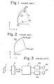
- Fig. 1 is an illustrative view useful in describing the path traversed by a tool in the prior art when the distances rA, rB are unequal;
- Fig. 2 is an illustrative view useful in describing a method of circular interpolation according to the prior art;
- Fig. 3 is a block diagram of a numerical control system which employs a circular interpolation apparatus according to the prior art;
- Fig. 4 is a block diagram of a circular interpolation apparatus for practicing the present invention; and
- Fig. 5 is an illustrative view useful for describing a method of circular interpolation according to the present invention.
- Figure 1 has already been described.
- In Fig. 2, if we let (io, jo) denote the coordi- nates of the center 0 of an arc for a case where the current position (arc starting point) Ps of a tool is taken as the standard, and let (xo, yo) denote the coordinates of the end point Pe of the arc, then a circular interpolation instruction will be given by:

- . The numerical control system shown in Fig. 3 includes a paper tape 1 bearing punched machining instructions, an
input control circuit 2, acircular interpolator 3 which operates on the basis of an algebraic method, as disclosed in "Introduction to Numerical Control Devices" by Seiuemon Inaba, 1970, pp. 21 - 35, or on the basis of a DDA (digital differential analyzing) method, well-known X-axis and Y-axis servo circuits axis servo motors - In operation, the
input control circuit 2 applies the arc information x , y , i , j to thecircular interpolator 3 when the circular interpolation instruction is read from the paper tape 1. Theinterpolator 3 executes a circular interpolation operation on the basis of the arc information and delivers the interpolation pulses X , Y to therespective servo circuits servo motors - . Fig. 4 illustrates the block diagram of an apparatus for practicing a circular interpolation method in accordance with the present invention, and Fig. 5 is an illustrative view useful in describing said method.
- In Fig. 4 there are provided a
paper tape 21 bearing the punched machining instructions, atape reader 22, and aninput control circuit 23 which includes decoders, registers and the like. When the circular interpolation instruction given by expression (1) is read from thepaper tape 21, a radiusarithmetic circuit 24 computes the distances OPs (namely rA) and OPe (namely rB) by executing the operations:

Registers arithmetic circuit 24. Acomparator circuit 27 compares rA and rB and issues a coincidence signal COI (logical "1") when they are equal, and a non-coincidence signal *COI (logical "1") when they are unequal. Numeral 28 denotes an arithmetic circuit for computing a new radius. Specifically, when the signal *COI is a "1", thearithmetic circuit 28 executes the operation:


multiplexer 30 outputs xo, yo, iN, when the signal *COI is a "1" The output of themultiplexer 30 is coupled to acircular interpolator 31. - embodiment of the The present/invention operates in the following manner.
- When the
paper tape 21 instructs the circular interpolation indicated by expression (1), theinput control circuit 23 stores the data xo, yo, io, in the internal registers and simultaneously delivers the data to the radiusarithmetic circuit 24. The latter executes the operations specified by equations (2) and (3) to compute the radii rA' rB which are stored in theregisters comparator circuit 27 compares the radii and delivers the coincidence signal COI (logical "1") when they are equal, and delivers the non-coincidence signal *COI (logical "1") when they are unequal. When the signal COI is a "1", themultiplexer 30 delivers the data xo, yo, io, jo to the circular inter-polator 31 which executes a known circular interpolation operation in the same manner as the conventional arrangement, thereby delivering interpolation pulses Xp, Yp to servo circuits which are not shown, the latter responding by rotatively driving the servo motors. - When the non-coincidence signal *COI goes to logical "1" in a case where rA and rB are unequal, the new radius
arithmetic circuit 28 executes the operation indicated by equation (4) to compute the new radius r. It may be appreciated from equation (4) that the new radius r is the arithmetic mean of the radii rA, rB. - Next, the new center
arithmetic circuit 29 computes the coordinates (iN,jN) of the new center ON using the equations (5) and (6). Since the signal *COI is a "1", the coordinates iN, jN are sent to thecircular interpolator 31 together with x and y0 via themultiplexer 30. Thecircular interpolator 31 executes a circular interpola- tion operation on the basis of xo, yo, iN and jN, delivering the interpolation pulses Xp, Y to the servo circuits (not shown) to rotatively drive the servo motors. As a result, a tool (not shwon) is moved from the arc starting point Os to the arc end point Pe along the arc of center ON, as indicated by the dot-and-dash line in Fig. 5, whereby the tool may machine a workpiece smoothly between the points Ps and Pe. embodiment and method according to the - In accordance with the present invention as described above, a movable object such as a tool or table can be moved along a curve or arc which smoothly connects a given starting point P and a given end point P even for a given arc instruction in which rA and rB are unequal. This makes it possible to achieve a higher level of machining precision, and facilitates the wire electrode back-up control operation in a wire cut-type electric discharge machine.
- Although the present invention has been described in relation to the embodiment shown in the accompanying drawings, various changes and modifications may be made in the invention without departing from the spirit and scope thereof as set forth in the appended claims. For example, rather than providing the individual hardware for the radius arithmetic circuit, new radius arithmetic circuit, new center arithmetic circuit and comparator circuit as described above, these functions may be integrated by using a microcomputer or the like. Moreover, the new radius, although found from equation (4) above, need not necessarily be computed using said equation.
Claims (10)

Applications Claiming Priority (2)
| Application Number | Priority Date | Filing Date | Title |
|---|---|---|---|
| JP124164/80 | 1980-09-08 | ||
| JP55124164A JPS5750010A (en) | 1980-09-08 | 1980-09-08 | Numeric control system |
Publications (3)
| Publication Number | Publication Date |
|---|---|
| EP0047653A2 true EP0047653A2 (en) | 1982-03-17 |
| EP0047653A3 EP0047653A3 (en) | 1983-02-16 |
| EP0047653B1 EP0047653B1 (en) | 1986-01-02 |
Family
ID=14878523
Family Applications (1)
| Application Number | Title | Priority Date | Filing Date |
|---|---|---|---|
| EP81304069A Expired EP0047653B1 (en) | 1980-09-08 | 1981-09-07 | Method and apparatus for circular interpolation |
Country Status (5)
| Country | Link |
|---|---|
| US (1) | US4458326A (en) |
| EP (1) | EP0047653B1 (en) |
| JP (1) | JPS5750010A (en) |
| KR (1) | KR880000273B1 (en) |
| DE (1) | DE3173372D1 (en) |
Cited By (2)
| Publication number | Priority date | Publication date | Assignee | Title |
|---|---|---|---|---|
| CN104133423B (en) * | 2014-07-16 | 2016-11-09 | 北京航空航天大学 | A Space Ellipse Arc Interpolation Method |
| DE102015013582B4 (en) | 2014-10-23 | 2018-08-09 | Fanuc Corporation | Numerical control device |
Families Citing this family (6)
| Publication number | Priority date | Publication date | Assignee | Title |
|---|---|---|---|---|
| FR2514530B1 (en) * | 1981-10-09 | 1987-06-19 | Lemoine Cie Ets | METHOD FOR INPUT OF REPRESENTATIVE DATA OF THE FORM OF AN OBJECT |
| JPH07104704B2 (en) * | 1986-05-19 | 1995-11-13 | 日本電気株式会社 | Curve interpolation method in numerical control |
| JPH068105A (en) * | 1992-06-29 | 1994-01-18 | Komatsu Ltd | Cylindrically machining device |
| DE4323992A1 (en) * | 1992-09-22 | 1994-03-24 | Bosch Gmbh Robert | Check on operational accuracy of numerically controlled machine including robot - involves interpolator in generation of vectors for servo control of sliders guided around circular test track |
| CN102428419B (en) * | 2009-06-03 | 2013-12-25 | 三菱电机株式会社 | Numerical control device and production system |
| CN103934528B (en) * | 2014-04-14 | 2016-02-10 | 上海交通大学 | A kind of six-axis linkage interpolating method for spark machined |
Family Cites Families (6)
| Publication number | Priority date | Publication date | Assignee | Title |
|---|---|---|---|---|
| NL291454A (en) * | 1959-12-24 | |||
| GB1319286A (en) * | 1969-06-21 | 1973-06-06 | Olivetti & Co Spa | Numerical control device |
| US3864613A (en) * | 1972-12-29 | 1975-02-04 | Hymie Cutler | Path generating system for numerical control apparatus |
| US4031369A (en) * | 1975-08-12 | 1977-06-21 | The Bendix Corporation | Interpolation and control apparatus and method for a numerical control system |
| JPS597963B2 (en) * | 1977-06-28 | 1984-02-22 | 沖電気工業株式会社 | Circular interpolation circuit in numerical control |
| US4150328A (en) * | 1977-09-14 | 1979-04-17 | Dana Corporation | Apparatus and method for controlling a machine tool along a circular path |
-
1980
- 1980-09-08 JP JP55124164A patent/JPS5750010A/en active Granted
-
1981
- 1981-08-19 US US06/294,248 patent/US4458326A/en not_active Expired - Lifetime
- 1981-09-02 KR KR8103273A patent/KR880000273B1/en not_active Expired
- 1981-09-07 EP EP81304069A patent/EP0047653B1/en not_active Expired
- 1981-09-07 DE DE8181304069T patent/DE3173372D1/en not_active Expired
Cited By (2)
| Publication number | Priority date | Publication date | Assignee | Title |
|---|---|---|---|---|
| CN104133423B (en) * | 2014-07-16 | 2016-11-09 | 北京航空航天大学 | A Space Ellipse Arc Interpolation Method |
| DE102015013582B4 (en) | 2014-10-23 | 2018-08-09 | Fanuc Corporation | Numerical control device |
Also Published As
| Publication number | Publication date |
|---|---|
| KR880000273B1 (en) | 1988-03-15 |
| EP0047653B1 (en) | 1986-01-02 |
| EP0047653A3 (en) | 1983-02-16 |
| JPS5750010A (en) | 1982-03-24 |
| JPS6211728B2 (en) | 1987-03-14 |
| US4458326A (en) | 1984-07-03 |
| DE3173372D1 (en) | 1986-02-13 |
Similar Documents
| Publication | Publication Date | Title |
|---|---|---|
| EP0145967B1 (en) | Curvilinear interpolation system and method | |
| EP0103351B1 (en) | Numerical control method and apparatus therefor | |
| EP0086846B1 (en) | Numerical control method | |
| EP0046032B1 (en) | Method of numerical control | |
| KR850000328B1 (en) | Numerical control method | |
| EP0880085B1 (en) | Adaptive feedrates from geometry modeling for nc machining | |
| EP0047653B1 (en) | Method and apparatus for circular interpolation | |
| EP0077177B1 (en) | Numerical control method and arrangement | |
| EP0176600A1 (en) | Accelerating/decelerating system for numerically controlled apparatus | |
| US4387327A (en) | Numerical control system for a crankshaft milling machine integral interpolators | |
| EP0102219A2 (en) | Acceleration/deceleration device for numerical controller | |
| EP0406784B1 (en) | Electronic polynomial interpolation device for numeric controls of machine tools, particularly milling machines for the machining of dies, and machine comprising said device | |
| EP0071378B1 (en) | Numerical control method and apparatus | |
| EP0364600B1 (en) | Round screw machining method | |
| EP1457852B1 (en) | Method and apparatus for preparing program for die machining | |
| EP1267236A1 (en) | Method and apparatus for setting moving data in a machine tool | |
| EP0200788B1 (en) | Method of returning rotary shaft to reference point | |
| US5347461A (en) | Tool travel path creating method | |
| EP0070135A1 (en) | A numerical control method and an nc system | |
| KR910007274B1 (en) | Cotton processing method | |
| JPH0731534B2 (en) | How to create an offset shape | |
| JPH07210225A (en) | Numerical controller | |
| KR100257611B1 (en) | Turning system & its tool path generation method | |
| KR0178585B1 (en) | Corner processing method of wire cut electric discharge machine | |
| KR0160672B1 (en) | Numerical Control Method and Apparatus for Mirror Image Control |
Legal Events
| Date | Code | Title | Description |
|---|---|---|---|
| PUAI | Public reference made under article 153(3) epc to a published international application that has entered the european phase |
Free format text: ORIGINAL CODE: 0009012 |
|
| AK | Designated contracting states |
Designated state(s): CH DE FR GB LI |
|
| RBV | Designated contracting states (corrected) |
Designated state(s): CH DE FR GB LI |
|
| RAP1 | Party data changed (applicant data changed or rights of an application transferred) |
Owner name: FANUC LIMITED |
|
| PUAL | Search report despatched |
Free format text: ORIGINAL CODE: 0009013 |
|
| AK | Designated contracting states |
Designated state(s): CH DE FR GB LI |
|
| 17P | Request for examination filed |
Effective date: 19830801 |
|
| RAP1 | Party data changed (applicant data changed or rights of an application transferred) |
Owner name: FANUC LTD |
|
| GRAA | (expected) grant |
Free format text: ORIGINAL CODE: 0009210 |
|
| AK | Designated contracting states |
Designated state(s): CH DE FR GB LI |
|
| REF | Corresponds to: |
Ref document number: 3173372 Country of ref document: DE Date of ref document: 19860213 |
|
| ET | Fr: translation filed | ||
| PLBE | No opposition filed within time limit |
Free format text: ORIGINAL CODE: 0009261 |
|
| STAA | Information on the status of an ep patent application or granted ep patent |
Free format text: STATUS: NO OPPOSITION FILED WITHIN TIME LIMIT |
|
| 26N | No opposition filed | ||
| PGFP | Annual fee paid to national office [announced via postgrant information from national office to epo] |
Ref country code: GB Payment date: 19910806 Year of fee payment: 11 |
|
| PGFP | Annual fee paid to national office [announced via postgrant information from national office to epo] |
Ref country code: FR Payment date: 19910819 Year of fee payment: 11 |
|
| PG25 | Lapsed in a contracting state [announced via postgrant information from national office to epo] |
Ref country code: GB Effective date: 19920907 |
|
| GBPC | Gb: european patent ceased through non-payment of renewal fee |
Effective date: 19920907 |
|
| PG25 | Lapsed in a contracting state [announced via postgrant information from national office to epo] |
Ref country code: FR Effective date: 19930528 |
|
| REG | Reference to a national code |
Ref country code: FR Ref legal event code: ST |
|
| PGFP | Annual fee paid to national office [announced via postgrant information from national office to epo] |
Ref country code: DE Payment date: 19980914 Year of fee payment: 18 |
|
| PGFP | Annual fee paid to national office [announced via postgrant information from national office to epo] |
Ref country code: CH Payment date: 19980929 Year of fee payment: 18 |
|
| PG25 | Lapsed in a contracting state [announced via postgrant information from national office to epo] |
Ref country code: LI Free format text: LAPSE BECAUSE OF NON-PAYMENT OF DUE FEES Effective date: 19990930 Ref country code: CH Free format text: LAPSE BECAUSE OF NON-PAYMENT OF DUE FEES Effective date: 19990930 |
|
| REG | Reference to a national code |
Ref country code: CH Ref legal event code: PL |
|
| PG25 | Lapsed in a contracting state [announced via postgrant information from national office to epo] |
Ref country code: DE Free format text: LAPSE BECAUSE OF NON-PAYMENT OF DUE FEES Effective date: 20000701 |