EP0047580B1 - Pflug mit verstellbarer Arbeitsbreite - Google Patents
Pflug mit verstellbarer Arbeitsbreite Download PDFInfo
- Publication number
- EP0047580B1 EP0047580B1 EP19810303507 EP81303507A EP0047580B1 EP 0047580 B1 EP0047580 B1 EP 0047580B1 EP 19810303507 EP19810303507 EP 19810303507 EP 81303507 A EP81303507 A EP 81303507A EP 0047580 B1 EP0047580 B1 EP 0047580B1
- Authority
- EP
- European Patent Office
- Prior art keywords
- plow
- forecarriage
- unit
- plow beam
- articulation
- Prior art date
- Legal status (The legal status is an assumption and is not a legal conclusion. Google has not performed a legal analysis and makes no representation as to the accuracy of the status listed.)
- Expired
Links
Images

Classifications
-
- A—HUMAN NECESSITIES
- A01—AGRICULTURE; FORESTRY; ANIMAL HUSBANDRY; HUNTING; TRAPPING; FISHING
- A01B—SOIL WORKING IN AGRICULTURE OR FORESTRY; PARTS, DETAILS, OR ACCESSORIES OF AGRICULTURAL MACHINES OR IMPLEMENTS, IN GENERAL
- A01B15/00—Elements, tools, or details of ploughs
- A01B15/14—Frames
-
- A—HUMAN NECESSITIES
- A01—AGRICULTURE; FORESTRY; ANIMAL HUSBANDRY; HUNTING; TRAPPING; FISHING
- A01B—SOIL WORKING IN AGRICULTURE OR FORESTRY; PARTS, DETAILS, OR ACCESSORIES OF AGRICULTURAL MACHINES OR IMPLEMENTS, IN GENERAL
- A01B15/00—Elements, tools, or details of ploughs
- A01B15/14—Frames
- A01B15/145—Frames the plough blades being connected to the plough beam for unisono adjustment of the furrow width
Definitions
- This invention relates to fully mounted plow systems, whether of the rollover type or not, and having a variable width, that is, plows in which the transverse spacing between furrow-cutting lines or so-called lines of action of two adjacent plow bottoms is adjustable in order to obtain correspondingly variable furrow pitch.
- FR-A-2401597 shows a plow system of this type, adapted to be mounted on and pulled by a tractor, the system comprising a hitch assembly including link arms spaced apart in a common, substantially horizontal plane and connected to the tractor at their forward ends and a forecarriage unit extending between and connected to the rearward ends of the link arms and capable of pivoting thereto about a horizontal axis.
- a forward end of a link is pivoted to the forecarriage unit about a vertical axis, and a rearward end of the link is pivoted to an elongate plow beam, again about a vertical axis, the plow beam thus being trailed behind the forecarriage unit and lying generally in a horizontal plane and inclined to the direction of forward travel.
- the plow beam has a rear ground-engaging wheel and carries a plurality of plow bottom assemblies, each pivotally attached to the plow beam through a support bracket, the assemblies being equally spaced along the plow beam.
- An elongate coupling member extends generally parallel to the plow beam and is pivotally connected to each of the support brackets to interconnect the plow bottom assemblies, thus forming a device of the deformable parallelogram type.
- Adjustment of the furrow pitch is obtained on the one hand by modifying the common angular position of the plow bottoms with respect to the plow beam and on the other hand by modifying the angular position of the beam with respect to the tractor in order to ensure that the lines of action of the plow bottoms are aligned with respect to the direction of forward travel. This is effected by a double acting hydraulic cylinder arrangement.
- the double problem encountered in gang plows lies in the fact that, on the one hand, the furrow-cutting lines or so-called lines of action of the plow bottoms must be parallel to the direction of forward travel while plowing is in progress and after or during adjustment of spacing of said lines of action and that, on the other hand, the line of action of the foremost plow bottom must be displaced transversely to the direction of forward travel in order to be located with respect to the furrow cut during the previous trip at a distance equal to the new spacing set by the furrows.
- the aim of the invention is to improve this type of plow.
- a fully mounted variable width plow system adapted to be mounted on and pulled by a tractor, said system comprising a hitch assembly including two link arms spaced apart in a common substantially horizontal plane and connected to the tractor at their forward ends, a forecarriage unit extending between and connected to the rearward ends of said link arms, an elongated plow beam extending generally in a horizontal plane and inclined to the direction of forward travel, means pivotally mounting said plow beam for pivotal movement relative to said forecarriage unit in a generally horizontal plane, a plurality of plow bottom assemblies each including a support bracket pivotally attached at a point of articulation to said plow beam for movement about a generally vertical pivot axis, the points being located so that said plow bottom assemblies are equally spaced along said plow beam, an elongated coupling member extending generally parallel to said plow beam and being pivotally connected about a generally vertical pivot axis to each of said support brackets to interconnect the plow bottom
- This configuration assists the plow bottoms to move into the correct work position automatically, that is to say without the aid of external control means, when a positive control action has set said plow bottoms angularly with respect to their common support beam so as to have the desired spacing between their lines of action.
- a single control device When making use of a system of this type, a single control device varies the spacing of the lines of action of the plow bottoms by pivotally displacing the plow bottoms on the plow beam. This has the effect of obtaining both a correction of inclination or in other words an alignment of the lines of action with respect to the direction of forward travel, and the suitable transverse displacement of the line of action of the foremost plow bottom.
- the forecarriage unit is constructed in two sections pivoted about a longitudinal axis, one section being coupled to the link-arms and the other section being adapted to carry the remainder of the system (plow beam, coupling member, control means, and so forth).
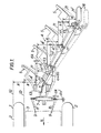
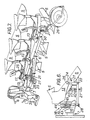
- a tractor 1 is represented by its rear wheels 2 and its frame 3.
- Said tractor draws a gang plow 4 which mainly comprises a plurality of plow bottoms 5, a plow beam 6 for supporting the bottoms and a forecarriage unit 7 for coupling the plow beam 6 to link-arms 8 of the three-point hitch system provided at the rear of tractors.
- a gang plow 4 which mainly comprises a plurality of plow bottoms 5, a plow beam 6 for supporting the bottoms and a forecarriage unit 7 for coupling the plow beam 6 to link-arms 8 of the three-point hitch system provided at the rear of tractors.
- link-arms 8 of the three-point hitch system provided at the rear of tractors.
- Said lower link-arms are substantially horizontal, converge in the forward direction and are each pivoted at their forward end on a respective vertical pin 9 to the tractor frame 3 to allow pivotal movement about vertical axes.
- the rearward ends of the links are each pivoted by a connection 39 to the forecarriage unit 7 again allowing relative pivotal displacement about vertical axes.
- the plow bottoms 5 are maintained parallel to each other and are capable of controlled pivotal displacement with respect to the plow beam 6 about vertical pivot-pins 10 which are uniformly spaced along the plow beam.
- Each plow bottom 5 has a furrow-cutting line or so-called line of action 11.
- the lines of action are aligned with respect to the direction V of forward travel.
- the spacing A or in other words the pitch of the furrows to be cut either increases or decreases as the case may be an amount dA so as to assume the value A'.
- the new line of action 11' of the foremost plow bottom which is aligned with respect to the direction of forward travel V must therefore be displaced by dA with respect to a line of action 11 which would have been the previous line of said foremost plow bottom without adjustment in order to ensure that the new furrow pitch is equal to A'.
- the plow as disclosed is so designed and arranged that, once the angle between the plow bottoms 5 and the plow beam 6 has been adjusted and fixed, said bottoms move of their own accord into a position which conforms to this double position-setting under the action of the resistance forces exerted by the soil on the plow bottoms and by free pivotal motion of the link-arms 8 which support the aforementioned assembly.
- the plow bottoms 5 are each rigidly fixed to a plow-bottom support bracket 13 which brackets are pivoted at uniform intervals on pivot-pins 10 to the plow beam 6 and on, pivot-pins 14 to a coupling member 15 consisting of a bar or connecting-rod which is of substantial length and is parallel to the plow beam 6.
- the pivot-pins 14 are also spaced at uniform intervals along member 15 and form collapsible parallelograms with the pivot-pins 10, with the result that when pivoted about pivot-pins 10 the plow bottoms 5 remain parallel to each other.
- the plurality of plow bottom assemblies interconnected by member 15 thus form a set of interconnected plow bottom assemblies.
- the forecarriage unit 7 has a longitudinal rear section or extension 16 and the plow beam 6 is pivotally mounted to unit 7 by a direct pivot connection 17 near the free end of said rear section.
- a coupling member 18 serves to connect the support bracket 13 of the foremost plow bottom 5 to the extension 16 and is pivotally attached to the bracket and the extension at 19 and 20 respectively.
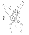
- the four pivot-pins 10, 17, 20, 19 (shown in Figure 3) form a quadrilateral which is normally deformable, that is the angles can be changed, and is made rigid by locking means which constitute at the same time means for adjusting the spacing of the lines of action 11 of the plow bottoms 5.
- the adjusting and locking means are constituted by a double-acting hydraulic cylinder 21, the cylinder portion 22 of which is pivotally mounted on the plow beam 6 at 23 and the rod portion 24 of which is pivotally mounted at 25 on the foremost support bracket 13 at a distance from the corresponding pivot-pin 10.
- the cylinder 21 and its rod portion could be mounted to action between the plow beam 6 and the coupling member 15 or another support bracket 13 or alternatively between the member 15 and one of the support brackets 13.
- the hydraulic cylinder 21 is controlled from the operator's deck of the tractor.
- the degree of extension of the hydraulic cylinder is representative of the angle made by the lines of action 11 of the plow bottoms 5 with the plow beam 6.
- Said extension is controlled from the operator's deck by any suitable means of known type and in such a manner as to ensure that the operator can indicate and obtain the desired angle of inclination of the plow bottoms with respect to the beam.
- the plow beam 6 and the forecarriage unit 7 undergo a displacement with respect to the tractor which is permitted by the pivotal connection of link-arms 8 to the tractor 1 and to the forecarriage unit 7.
- the new lines of action 11' are displaced transversely with respect to the first lines of action 11 over distances which are defined by the geometry of the assembly.
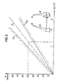
- the variation dA in spacing of the lines of action of the plow bottoms is a simple trigonometric function of the initial angle a of the lines of action with the plow beam and of the variation da of said angle and said variation is proportional to the spacing L of the bottoms along the plow beam.
- the spacing L is within the range of 700 mm to 1000 mm
- the angle a is within the range of 25° to 30°
- the variation da is of small magnitude, namely a maximum of 5° above and below the value a.
- the variation da of the angle a causes the following movements by deformation of the quadrilateral: rotation da of each plow bottom 5 about its pivot-pin 10, rotation da" of the forecarriage unit about the pivot-pin 17 and relative rotation da' of the forecarriage unit 7 with respect to the plow bottoms.
- the forecarriage unit 7 After such an adjustment has been completed and the plow is pulled forward the bottoms return automatically to the position of alignment with respect to the direction of forward travel V, the forecarriage unit 7 therefore undergoes a pivotal displacement through the angle da' by rotation of the link-arms 8 about the pivots 9 and 39.
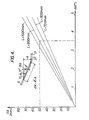
- the forecarriage unit 7 also undergoes a displacement which has a component transversely to the direction V, the value e, see Figure 5, of said component being a simple function of the quadrilateral formed by the two arms 8.
- curve D which is representative of the value of e as a function of da' in respect of low values of da'.
- the values of e are expressed in millimeters in ordinates and the values of da' are expressed in degrees in abscissae.
- the two straight lines D 11 D 2 represent the values of e as a function of da' in the case of extreme types of link-arms 8 at present in existence, the straight line D being the line of mean values between the values of e on the straight lines D 1 and D 2 .
- the geometry of the quadrilateral 10, 17, 20, 19 (shown in Figure 3) is such that the angle da' through which the forecarriage unit 7 rotates in response to the adjustment and to the fact that the plow bottoms are maintained in a position of alignment with respect to the direction of forward travel V results in a transverse displacement of the forecarriage unit 7, the value e of said displacement being equal to the variation dA in spacing of the lines of action of the plow bottoms.
- the result thereby achieved is that the line of action of the foremost plow bottom 5 undergoes a transverse displacement during adjustment by a quantity equal to the variation in spacing of the lines of action of the plow bottoms.
- the long base of the trapezoid is defined by the points of articulation 17, 20, the short base of the trapezoid is defined by the points of articulation 10, 19 and the short side perpendicular to the bases is defined by the points of articulation 19, 20.
- the angular variations da and da are in the ratio of 8 1 to 8 2 with a sufficient approximation, small angular variations being taken into account.
- the plow beam 6 is equipped at the rear with at least one gauge wheel 26 which bears on the ground.
- Gauge wheel 26 is pivotally mounted to the beam 6 at 50 and includes a lever arm 52 which is pivoted to coupling member 15 at 53 such that the expansion or contraction of hydraulic cylinder 21 results in pivotal movement of gauge wheel 26.
- hydraulic cylinder 21 When hydraulic cylinder 21 is expanded, thereby increasing the spacing between furrows, gauge wheel 26 is pivoted in the counterclockwise direction to thus properly position it for the new attitude of the plow beam 6.
- gauge wheel 26 is pivoted in the clockwise direction and again assumes the proper attitude for the narrower furrow spacing.
- the rear section or extension 16 of the forecarriage unit 7 is capable of pivotal displacement about a longitudinal axis through an angle of 180°.
- a transverse lead-screw 28 is journaled in a member 43 and is threaded through a block 44 which carries pivot pin 19.
- the block 44 is confined to slide within a smooth-walled sleeve 45 integral with coupling member 18.
- Figure 7 is an illustration of the subject invention incorporated into a fully mounted two way or rollover plow.
- Conventional reversing mechanism and trip mechanism such as disclosed in the previous mentioned U.S. Patent No. 3,554,294 and U.S. Patent No 3,662,840, respectively, can be utilized in a two way plow of this type and have no effect upon the subject invention.
- the forecarriage unit 7 includes a front section and rear section 16 which are pivotally connected to permit pivotal displacement of the rear section relative to the front section about a longitudinal axis through the angle of 180°.
Landscapes
- Life Sciences & Earth Sciences (AREA)
- Engineering & Computer Science (AREA)
- Mechanical Engineering (AREA)
- Soil Sciences (AREA)
- Environmental Sciences (AREA)
- Soil Working Implements (AREA)
Claims (5)
Applications Claiming Priority (2)
| Application Number | Priority Date | Filing Date | Title |
|---|---|---|---|
| FR8017726 | 1980-08-12 | ||
| FR8017726A FR2488479A1 (fr) | 1980-08-12 | 1980-08-12 | Charrue multi-socs a largeur variable |
Publications (2)
| Publication Number | Publication Date |
|---|---|
| EP0047580A1 EP0047580A1 (de) | 1982-03-17 |
| EP0047580B1 true EP0047580B1 (de) | 1986-02-19 |
Family
ID=9245112
Family Applications (1)
| Application Number | Title | Priority Date | Filing Date |
|---|---|---|---|
| EP19810303507 Expired EP0047580B1 (de) | 1980-08-12 | 1981-07-31 | Pflug mit verstellbarer Arbeitsbreite |
Country Status (3)
| Country | Link |
|---|---|
| EP (1) | EP0047580B1 (de) |
| DE (1) | DE3173802D1 (de) |
| FR (1) | FR2488479A1 (de) |
Families Citing this family (9)
| Publication number | Priority date | Publication date | Assignee | Title |
|---|---|---|---|---|
| FR2523398B1 (fr) * | 1982-03-19 | 1987-01-23 | Case Sa Ji | Charrue multi-socs a largeur de travail variable |
| NO152231C (no) * | 1982-06-28 | 1985-08-28 | Kverneland As | Anordning ved jordbruksredskap, saerlig flerskjaersplog |
| GB2135562B (en) * | 1983-03-03 | 1986-09-24 | Dowdeswell C V R | Plough offset adjustment |
| AT378655B (de) * | 1983-08-05 | 1985-09-10 | Vogel & Noot Landmasch | Anbau- oder aufsatteldrehpflug |
| NL8402585A (nl) * | 1984-08-24 | 1986-03-17 | Texas Industries Inc | Ploeg. |
| DE3739140A1 (de) * | 1987-08-28 | 1989-03-09 | Bayerische Pflugfabrik Gmbh | Pflug |
| FR2789842B1 (fr) * | 1999-02-18 | 2001-04-27 | Mecanique Agricole Generale | Charrue a largeur variable |
| RU2470503C1 (ru) * | 2011-07-11 | 2012-12-27 | Федеральное государственное образовательное учреждение высшего профессионального образования "Челябинская государственная агроинженерная академия" | Плуг с регулируемыми параметрами лемешно-отвальной поверхности рабочих органов |
| EP3970461A1 (de) * | 2020-09-17 | 2022-03-23 | CNH Industrial Sweden AB | Verbesserte trägerbefestigungsklammer |
Family Cites Families (7)
| Publication number | Priority date | Publication date | Assignee | Title |
|---|---|---|---|---|
| FR1473287A (fr) * | 1966-02-02 | 1967-03-17 | Internat Harvester France | Perfectionnement aux charrues à plusieurs éléments de travail |
| US3554294A (en) * | 1967-04-24 | 1971-01-12 | Int Harvester Co | Reversing mechanism for two-way plows |
| GB1459923A (en) * | 1974-01-09 | 1976-12-31 | Ransomes Sims & Jefferies Ltd | Multi-furrow ploughs |
| DE7631356U1 (de) * | 1976-10-07 | 1977-02-17 | Rabewerk Heinrich Clausing, 4515 Bad Essen | Drehpflug |
| US4186806A (en) * | 1977-09-06 | 1980-02-05 | International Harvester Company | Plow system |
| FR2418611A1 (fr) * | 1978-03-03 | 1979-09-28 | Thieme Gerard | Charrue |
| DE2845111A1 (de) * | 1978-10-17 | 1980-04-24 | Lemken Kg Pflugfab | Getriebe zur verstellung der breite und des ideellen schlepperzugpunktes eines pfluges |
-
1980
- 1980-08-12 FR FR8017726A patent/FR2488479A1/fr active Granted
-
1981
- 1981-07-31 EP EP19810303507 patent/EP0047580B1/de not_active Expired
- 1981-07-31 DE DE8181303507T patent/DE3173802D1/de not_active Expired
Also Published As
| Publication number | Publication date |
|---|---|
| EP0047580A1 (de) | 1982-03-17 |
| DE3173802D1 (en) | 1986-03-27 |
| FR2488479A1 (fr) | 1982-02-19 |
| FR2488479B1 (de) | 1984-03-16 |
Similar Documents
| Publication | Publication Date | Title |
|---|---|---|
| US4415040A (en) | Fully mounted variable width plow | |
| US4186806A (en) | Plow system | |
| US4098346A (en) | Steering for plow with adjustable plow bottoms | |
| US4317489A (en) | Ground-working implement and lift linkage therefor | |
| US3481407A (en) | Plow | |
| US4762183A (en) | Farming implement with adjustable earthworking tool framer | |
| EP0047580B1 (de) | Pflug mit verstellbarer Arbeitsbreite | |
| US3817333A (en) | Plow system with plurality of plow units and means for adjusting spacing between units in a continuous manner | |
| US4450917A (en) | Self-leveling arrangement for agricultural implement frame | |
| CA1197720A (en) | Plow | |
| US7204319B2 (en) | Jointed rockshaft with angularly adjustable segments | |
| US4036305A (en) | Gang plow | |
| CA1073728A (en) | Multi-unit adjustable plow with articulated frame | |
| US2689514A (en) | Agricultural implement | |
| CA1095237A (en) | Land leveling apparatus | |
| US5669452A (en) | Blade plow with vertically reciprocating blades | |
| US4606413A (en) | Hydraulic leveler arrangement | |
| US5024281A (en) | Reversible moldboard plow | |
| US2375026A (en) | Tractor implement | |
| US4236587A (en) | Ground-working apparatus and hitch assembly therefor | |
| EP1261248B1 (de) | Vorrichtung zur bodenkopierung für vorsatzgeräte an erntemaschinen | |
| US4253528A (en) | Pivoting dual land wheel for a plow | |
| US4553609A (en) | Gang plow of varible working width | |
| US3603405A (en) | Device for automatically landing a semi-integral moldboard plow | |
| EP0181039B1 (de) | Pflug |
Legal Events
| Date | Code | Title | Description |
|---|---|---|---|
| PUAI | Public reference made under article 153(3) epc to a published international application that has entered the european phase |
Free format text: ORIGINAL CODE: 0009012 |
|
| AK | Designated contracting states |
Designated state(s): DE GB IT SE |
|
| 17P | Request for examination filed |
Effective date: 19820910 |
|
| RAP1 | Party data changed (applicant data changed or rights of an application transferred) |
Owner name: J. I. CASE COMPANY |
|
| GRAA | (expected) grant |
Free format text: ORIGINAL CODE: 0009210 |
|
| ITF | It: translation for a ep patent filed |
Owner name: BARZANO' E ZANARDO ROMA S.P.A. |
|
| AK | Designated contracting states |
Designated state(s): DE GB IT SE |
|
| REF | Corresponds to: |
Ref document number: 3173802 Country of ref document: DE Date of ref document: 19860327 |
|
| PLBE | No opposition filed within time limit |
Free format text: ORIGINAL CODE: 0009261 |
|
| STAA | Information on the status of an ep patent application or granted ep patent |
Free format text: STATUS: NO OPPOSITION FILED WITHIN TIME LIMIT |
|
| 26N | No opposition filed | ||
| ITPR | It: changes in ownership of a european patent |
Owner name: CESSIONE;CASE POCLAIN S.A. |
|
| REG | Reference to a national code |
Ref country code: GB Ref legal event code: 732 |
|
| ITTA | It: last paid annual fee | ||
| EAL | Se: european patent in force in sweden |
Ref document number: 81303507.8 |
|
| PGFP | Annual fee paid to national office [announced via postgrant information from national office to epo] |
Ref country code: SE Payment date: 19960716 Year of fee payment: 16 |
|
| PGFP | Annual fee paid to national office [announced via postgrant information from national office to epo] |
Ref country code: GB Payment date: 19960722 Year of fee payment: 16 |
|
| PGFP | Annual fee paid to national office [announced via postgrant information from national office to epo] |
Ref country code: DE Payment date: 19960930 Year of fee payment: 16 |
|
| PG25 | Lapsed in a contracting state [announced via postgrant information from national office to epo] |
Ref country code: GB Free format text: LAPSE BECAUSE OF NON-PAYMENT OF DUE FEES Effective date: 19970731 |
|
| PG25 | Lapsed in a contracting state [announced via postgrant information from national office to epo] |
Ref country code: SE Free format text: LAPSE BECAUSE OF NON-PAYMENT OF DUE FEES Effective date: 19970801 |
|
| GBPC | Gb: european patent ceased through non-payment of renewal fee |
Effective date: 19970731 |
|
| PG25 | Lapsed in a contracting state [announced via postgrant information from national office to epo] |
Ref country code: DE Free format text: LAPSE BECAUSE OF NON-PAYMENT OF DUE FEES Effective date: 19980401 |
|
| EUG | Se: european patent has lapsed |
Ref document number: 81303507.8 |