EP0047131A2 - Klemme für Kabel, Rohre und dgl. - Google Patents
Klemme für Kabel, Rohre und dgl. Download PDFInfo
- Publication number
- EP0047131A2 EP0047131A2 EP81303899A EP81303899A EP0047131A2 EP 0047131 A2 EP0047131 A2 EP 0047131A2 EP 81303899 A EP81303899 A EP 81303899A EP 81303899 A EP81303899 A EP 81303899A EP 0047131 A2 EP0047131 A2 EP 0047131A2
- Authority
- EP
- European Patent Office
- Prior art keywords
- nut
- screw
- channel
- clamp
- base
- Prior art date
- Legal status (The legal status is an assumption and is not a legal conclusion. Google has not performed a legal analysis and makes no representation as to the accuracy of the status listed.)
- Granted
Links
- 239000002184 metal Substances 0.000 claims description 4
- 239000000463 material Substances 0.000 claims description 2
- 238000000429 assembly Methods 0.000 description 2
- 229920001084 poly(chloroprene) Polymers 0.000 description 2
- 230000006835 compression Effects 0.000 description 1
- 238000007906 compression Methods 0.000 description 1
- 238000009434 installation Methods 0.000 description 1
- 229920003023 plastic Polymers 0.000 description 1
- 239000004033 plastic Substances 0.000 description 1
- 238000000926 separation method Methods 0.000 description 1
Images
Classifications
-
- F—MECHANICAL ENGINEERING; LIGHTING; HEATING; WEAPONS; BLASTING
- F16—ENGINEERING ELEMENTS AND UNITS; GENERAL MEASURES FOR PRODUCING AND MAINTAINING EFFECTIVE FUNCTIONING OF MACHINES OR INSTALLATIONS; THERMAL INSULATION IN GENERAL
- F16L—PIPES; JOINTS OR FITTINGS FOR PIPES; SUPPORTS FOR PIPES, CABLES OR PROTECTIVE TUBING; MEANS FOR THERMAL INSULATION IN GENERAL
- F16L3/00—Supports for pipes, cables or protective tubing, e.g. hangers, holders, clamps, cleats, clips, brackets
- F16L3/02—Supports for pipes, cables or protective tubing, e.g. hangers, holders, clamps, cleats, clips, brackets partly surrounding the pipes, cables or protective tubing
- F16L3/04—Supports for pipes, cables or protective tubing, e.g. hangers, holders, clamps, cleats, clips, brackets partly surrounding the pipes, cables or protective tubing and pressing it against a wall or other support
-
- F—MECHANICAL ENGINEERING; LIGHTING; HEATING; WEAPONS; BLASTING
- F16—ENGINEERING ELEMENTS AND UNITS; GENERAL MEASURES FOR PRODUCING AND MAINTAINING EFFECTIVE FUNCTIONING OF MACHINES OR INSTALLATIONS; THERMAL INSULATION IN GENERAL
- F16B—DEVICES FOR FASTENING OR SECURING CONSTRUCTIONAL ELEMENTS OR MACHINE PARTS TOGETHER, e.g. NAILS, BOLTS, CIRCLIPS, CLAMPS, CLIPS OR WEDGES; JOINTS OR JOINTING
- F16B2/00—Friction-grip releasable fastenings
- F16B2/02—Clamps, i.e. with gripping action effected by positive means other than the inherent resistance to deformation of the material of the fastening
- F16B2/06—Clamps, i.e. with gripping action effected by positive means other than the inherent resistance to deformation of the material of the fastening external, i.e. with contracting action
- F16B2/065—Clamps, i.e. with gripping action effected by positive means other than the inherent resistance to deformation of the material of the fastening external, i.e. with contracting action using screw-thread elements
-
- F—MECHANICAL ENGINEERING; LIGHTING; HEATING; WEAPONS; BLASTING
- F16—ENGINEERING ELEMENTS AND UNITS; GENERAL MEASURES FOR PRODUCING AND MAINTAINING EFFECTIVE FUNCTIONING OF MACHINES OR INSTALLATIONS; THERMAL INSULATION IN GENERAL
- F16L—PIPES; JOINTS OR FITTINGS FOR PIPES; SUPPORTS FOR PIPES, CABLES OR PROTECTIVE TUBING; MEANS FOR THERMAL INSULATION IN GENERAL
- F16L3/00—Supports for pipes, cables or protective tubing, e.g. hangers, holders, clamps, cleats, clips, brackets
- F16L3/24—Supports for pipes, cables or protective tubing, e.g. hangers, holders, clamps, cleats, clips, brackets with a special member for attachment to profiled girders
- F16L3/243—Supports for pipes, cables or protective tubing, e.g. hangers, holders, clamps, cleats, clips, brackets with a special member for attachment to profiled girders the special member being inserted in the profiled girder
-
- H—ELECTRICITY
- H02—GENERATION; CONVERSION OR DISTRIBUTION OF ELECTRIC POWER
- H02G—INSTALLATION OF ELECTRIC CABLES OR LINES, OR OF COMBINED OPTICAL AND ELECTRIC CABLES OR LINES
- H02G3/00—Installations of electric cables or lines or protective tubing therefor in or on buildings, equivalent structures or vehicles
- H02G3/30—Installations of cables or lines on walls, floors or ceilings
- H02G3/32—Installations of cables or lines on walls, floors or ceilings using mounting clamps
-
- Y—GENERAL TAGGING OF NEW TECHNOLOGICAL DEVELOPMENTS; GENERAL TAGGING OF CROSS-SECTIONAL TECHNOLOGIES SPANNING OVER SEVERAL SECTIONS OF THE IPC; TECHNICAL SUBJECTS COVERED BY FORMER USPC CROSS-REFERENCE ART COLLECTIONS [XRACs] AND DIGESTS
- Y10—TECHNICAL SUBJECTS COVERED BY FORMER USPC
- Y10T—TECHNICAL SUBJECTS COVERED BY FORMER US CLASSIFICATION
- Y10T24/00—Buckles, buttons, clasps, etc.
- Y10T24/44—Clasp, clip, support-clamp, or required component thereof
- Y10T24/44265—Gripping member face integral with or rigidly affixed to screw-driving portion
-
- Y—GENERAL TAGGING OF NEW TECHNOLOGICAL DEVELOPMENTS; GENERAL TAGGING OF CROSS-SECTIONAL TECHNOLOGIES SPANNING OVER SEVERAL SECTIONS OF THE IPC; TECHNICAL SUBJECTS COVERED BY FORMER USPC CROSS-REFERENCE ART COLLECTIONS [XRACs] AND DIGESTS
- Y10—TECHNICAL SUBJECTS COVERED BY FORMER USPC
- Y10T—TECHNICAL SUBJECTS COVERED BY FORMER US CLASSIFICATION
- Y10T24/00—Buckles, buttons, clasps, etc.
- Y10T24/44—Clasp, clip, support-clamp, or required component thereof
- Y10T24/44641—Clasp, clip, support-clamp, or required component thereof having gripping member formed from, biased by, or mounted on resilient member
Definitions
- This invention relates to clamps for securing cables, pipes and the like (hereinafter, for convenience, referred to as cables) and is particularly concerned with clamps of the kind comprising a channel member having limbs which in use lie one on each side of the cable or cables to be secured and which are shaped at their free ends for engagement with a support, and a saddle positioned inside the channel member and urged towards the free ends of the limbs by a screw bearing on the base of the channel, to secure the cable or cables between the saddle and the support.
- This type of clamp has the advantages that it only needs to be slightly wider than the cable or cables to be secured, and that it can be mounted and secured quickly as only one easily accessible screw needs to be tightened.
- Its main disadvantage is that a great variety of shapes and sizes are required to cater for variations in the shape and size of the support (which might be, among other things, an angle member, channel, girder, ladder rung, cable tray or structural tube) as well as in the number, size and cross-sectional shape of the cable or cables, hence requiring large stocks, at great expense, to be kept to cover a wide range of sizes and shapes of cables and supports.
- Some designs currently on the market are liable to slacken due to creep when used on thermoplastic-sheathed cables.
- Other known designs which incorporate a spring to avoid the risk of slackening, can disintegrate if the limbs are splayed apart during attempted fitting.
- a clamp for securing at least one cable to a support comprises a channel member having an apertured base and limbs shaped at their free ends for engagement with the support, and a sub-assembly comprising a screw, a saddle captive on the end of the screw remote from the screw head and positioned inside the channel member, and a nut threaded on the shank of the screw between the screw head and the saddle, the aperture in the base of the channel being large enough to permit passage of the head of the screw, but not so large as to permit passage of the nut.
- the relatively expensive screw and saddle sub-assembly is separable from the channel member and can be stocked separately; it may be the same for a considerable number of shapes and sizes of channel member, so that only the relatively cheap channel members need be stocked in large numbers to cover a wide range of sizes and shapes of cables and supports.
- the sub-assembly is positioned inside the channel member and the screw head passed through the aperture; the limbs of the channel member are engaged with the support to straddle the cable or cables on the support; on turning the screw head relative to the nut so that the separation of the nut and the screw head is reduced, the saddle is urged towards the cable or cables to secure the cable or cables between the saddle and the support, and the nut bears directly or indirectly on the inside of the base of the channel to tighten the clamp.
- the nut is rectangular or otherwise shaped to engage the limbs of the channel to prevent rotation of the nut when the screw is rotated.
- the sub-assembly preferably includes a resilient member located on the side of the nut nearer the screw head, so that the nut bears on the channel base through the resilient member.
- this resilient member is secured in the sub-assembly by being captive between the screw head and the nut and/or being bonded or otherwise secured to the nut.
- the resilient member is preferably of a rubbery polymeric material, such as polychloroprene.
- the resilient member may be a compression spring.
- the nut comprises a slightly flexible, sheet-metal member having a threaded aperture for engaging the screw and spaced from the aperture on at least one face of the nut at least one upstanding bearing surface comprising a minor part of the surface area of said face, which can bear on the base of the channel. or on the resilient member.
- the upstanding bearing surface of the nut bears on the base of the channel, or on the resilient member, and then the nut flexes in such a way that it locks the screw against unintentional rotation.
- said face of the nut has two upstanding bearing surfaces in the form of two ridges of the same height, substantially parallel to one another, and equally spaced on opposite sides of the axis of the aperture.
- the invention also includes a kit of parts consisting of a plurality of clamping means each comprising a sub-assembly as hereinbefore defined, all the sub-assemblies being alike, and a larger number of channel members all as hereinbefore defined and all dimensioned for use with the said sub-assemblies but including at least two channel members that differ in the spacing and/or length and/or the support engaging shapes of the limbs.
- the invention further includes an installation comprising at least one cable, supported by one or more of the clamps as hereinbefore described.
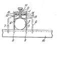
- the invention is now described, by way of example, with reference to the accompanying drawing in which the sole figure is a side view of a clamp for securing at least one cable.
- the clamp comprises a stamped sheet metal channel member having a base 1 with a clearance aperture 2 and limbs 3, 4 which may be straight to accommodate a small cable 5 or stepped outwards as shown in dotted outline 6, 7 to secure a larger cable (not shown), or two or more smaller cables (not shown) positioned side by side.
- the free ends of the limbs 8, 9 are shaped to engage a support 10.
- the remainder of the clamp consists of an inseparable sub-assembly comprising a screw 11 (with a head small enough to pass through the aperture 2), a rectangular sheet metal nut 12 threaded on the shank of the screw, a saddle 13 captively attached to the end of the shank, and a rectangular polychloroprene washer 14 push-fitted on the shank of the screw between its head and the nut, such that the nut bears on the base 1 of the channel through the washer, so providing resilience to compensate for any creep in the cable after clamping.
- the nut 12 is formed with stamped ridges 15 which provide upstanding bearing surfaces which bear on the washer 14.
- the sub-assembly and the channel member may be secured together in any convenient manner, for example by a slotted plastics washer (not shown) force-fitted on the shank of the screw after assembly and bearing on the outside of the base of the channel member.
- a slotted plastics washer (not shown) force-fitted on the shank of the screw after assembly and bearing on the outside of the base of the channel member.
Landscapes
- Engineering & Computer Science (AREA)
- General Engineering & Computer Science (AREA)
- Mechanical Engineering (AREA)
- Architecture (AREA)
- Civil Engineering (AREA)
- Structural Engineering (AREA)
- Supports For Pipes And Cables (AREA)
- Clamps And Clips (AREA)
- Installation Of Indoor Wiring (AREA)
- Laying Of Electric Cables Or Lines Outside (AREA)
- Mutual Connection Of Rods And Tubes (AREA)
- Communication Cables (AREA)
- Addition Polymer Or Copolymer, Post-Treatments, Or Chemical Modifications (AREA)
- Surgical Instruments (AREA)
- Connection Of Plates (AREA)
Priority Applications (1)
| Application Number | Priority Date | Filing Date | Title |
|---|---|---|---|
| AT81303899T ATE7949T1 (de) | 1980-08-27 | 1981-08-26 | Klemme fuer kabel, rohre und dgl. |
Applications Claiming Priority (2)
| Application Number | Priority Date | Filing Date | Title |
|---|---|---|---|
| GB8027683 | 1980-08-27 | ||
| GB8027683 | 1980-08-27 |
Publications (3)
| Publication Number | Publication Date |
|---|---|
| EP0047131A2 true EP0047131A2 (de) | 1982-03-10 |
| EP0047131A3 EP0047131A3 (en) | 1982-05-05 |
| EP0047131B1 EP0047131B1 (de) | 1984-06-13 |
Family
ID=10515666
Family Applications (1)
| Application Number | Title | Priority Date | Filing Date |
|---|---|---|---|
| EP81303899A Expired EP0047131B1 (de) | 1980-08-27 | 1981-08-26 | Klemme für Kabel, Rohre und dgl. |
Country Status (13)
| Country | Link |
|---|---|
| US (1) | US4419795A (de) |
| EP (1) | EP0047131B1 (de) |
| JP (1) | JPS5773211A (de) |
| AT (1) | ATE7949T1 (de) |
| CA (1) | CA1159036A (de) |
| DE (1) | DE3164180D1 (de) |
| DK (1) | DK367581A (de) |
| ES (1) | ES260060Y (de) |
| GB (2) | GB2082712A (de) |
| HK (1) | HK14985A (de) |
| NO (1) | NO812878L (de) |
| SG (1) | SG88384G (de) |
| ZA (1) | ZA815607B (de) |
Families Citing this family (1)
| Publication number | Priority date | Publication date | Assignee | Title |
|---|---|---|---|---|
| US20060284027A1 (en) * | 2005-04-04 | 2006-12-21 | Thomsa & Betts International, Inc. | Anti-vibration locking device for pipe and cable clamps |
Citations (6)
| Publication number | Priority date | Publication date | Assignee | Title |
|---|---|---|---|---|
| DE1694503U (de) * | 1954-06-21 | 1955-03-10 | Niedergesaess & Co | Buegelschelle fuer fassontragelsen oder registerschienen. |
| US2938692A (en) * | 1956-08-22 | 1960-05-31 | Lockheed Aircraft Corp | Cable clamp support |
| GB952163A (en) * | 1959-03-10 | 1964-03-11 | Cable Supports Ltd | Improvements in or relating to hangers for elongated members such as electric cablesor pipes |
| DE1251093B (de) * | 1967-09-28 | |||
| DE7817765U1 (de) * | 1978-09-28 | Thyssen Industrie Ag, 4300 Essen | Klemmvorrichtung mit Sehnappverschluß | |
| FR2415224A1 (fr) * | 1978-01-21 | 1979-08-17 | Kratzer F Mefa Duebel Gmbh | Dispositif pour fixer un corps allonge a un corps fixe et en particulier un tube a un ouvrage de maconnerie |
Family Cites Families (5)
| Publication number | Priority date | Publication date | Assignee | Title |
|---|---|---|---|---|
| US1398604A (en) * | 1919-10-31 | 1921-11-29 | Schweinert Maximilian Charles | Rim-nut |
| US2476863A (en) * | 1944-05-13 | 1949-07-19 | Kwikform Ltd | Scaffolding clamp |
| US2679872A (en) * | 1949-10-04 | 1954-06-01 | Rapid Metal Developments Ltd | Clamp for assembly of temporary structures |
| SU626290A1 (ru) * | 1976-10-14 | 1978-09-30 | Всесоюзный Ордена Трудового Красного Знамени Научно-Исследовательский Институт Сельскохозяйственного Машиностроения Им.В.П.Горячкина | Гайка дл винтовой передачи |
| US4269248A (en) * | 1979-04-20 | 1981-05-26 | Maclean-Fogg Company | Fastener with flexible flange |
-
1981
- 1981-08-13 ZA ZA815607A patent/ZA815607B/xx unknown
- 1981-08-17 US US06/293,108 patent/US4419795A/en not_active Expired - Fee Related
- 1981-08-19 DK DK367581A patent/DK367581A/da unknown
- 1981-08-20 ES ES1981260060U patent/ES260060Y/es not_active Expired
- 1981-08-25 JP JP56132201A patent/JPS5773211A/ja active Pending
- 1981-08-25 NO NO812878A patent/NO812878L/no unknown
- 1981-08-26 CA CA000384619A patent/CA1159036A/en not_active Expired
- 1981-08-26 EP EP81303899A patent/EP0047131B1/de not_active Expired
- 1981-08-26 AT AT81303899T patent/ATE7949T1/de not_active IP Right Cessation
- 1981-08-26 GB GB8126042A patent/GB2082712A/en active Pending
- 1981-08-26 DE DE8181303899T patent/DE3164180D1/de not_active Expired
- 1981-08-26 GB GB8126043A patent/GB2082670B/en not_active Expired
-
1984
- 1984-12-15 SG SG883/84A patent/SG88384G/en unknown
-
1985
- 1985-02-28 HK HK149/85A patent/HK14985A/xx unknown
Patent Citations (6)
| Publication number | Priority date | Publication date | Assignee | Title |
|---|---|---|---|---|
| DE1251093B (de) * | 1967-09-28 | |||
| DE7817765U1 (de) * | 1978-09-28 | Thyssen Industrie Ag, 4300 Essen | Klemmvorrichtung mit Sehnappverschluß | |
| DE1694503U (de) * | 1954-06-21 | 1955-03-10 | Niedergesaess & Co | Buegelschelle fuer fassontragelsen oder registerschienen. |
| US2938692A (en) * | 1956-08-22 | 1960-05-31 | Lockheed Aircraft Corp | Cable clamp support |
| GB952163A (en) * | 1959-03-10 | 1964-03-11 | Cable Supports Ltd | Improvements in or relating to hangers for elongated members such as electric cablesor pipes |
| FR2415224A1 (fr) * | 1978-01-21 | 1979-08-17 | Kratzer F Mefa Duebel Gmbh | Dispositif pour fixer un corps allonge a un corps fixe et en particulier un tube a un ouvrage de maconnerie |
Also Published As
| Publication number | Publication date |
|---|---|
| HK14985A (en) | 1985-03-08 |
| ZA815607B (en) | 1982-08-25 |
| EP0047131A3 (en) | 1982-05-05 |
| ES260060Y (es) | 1982-10-16 |
| ES260060U (es) | 1982-03-16 |
| GB2082670A (en) | 1982-03-10 |
| JPS5773211A (en) | 1982-05-07 |
| US4419795A (en) | 1983-12-13 |
| DE3164180D1 (en) | 1984-07-19 |
| GB2082670B (en) | 1984-09-05 |
| CA1159036A (en) | 1983-12-20 |
| GB2082712A (en) | 1982-03-10 |
| SG88384G (en) | 1985-06-07 |
| NO812878L (no) | 1982-03-01 |
| DK367581A (da) | 1982-02-28 |
| EP0047131B1 (de) | 1984-06-13 |
| ATE7949T1 (de) | 1984-06-15 |
Similar Documents
| Publication | Publication Date | Title |
|---|---|---|
| US5368261A (en) | Cable mount and fixture | |
| CA1311233C (en) | Support systems for pipes and other loads | |
| US4798029A (en) | Hold-down clamp | |
| US4934886A (en) | Fastening assembly and method of fastening | |
| US3894707A (en) | Mounting devices | |
| US6079673A (en) | Transmission line hanger | |
| US4666355A (en) | Top grip lock nut assembly | |
| US5274888A (en) | Adjustable U-bolt type pipe clamp | |
| US4637178A (en) | Screen assembly and clip therefor | |
| EP0210042B1 (de) | Befestigung für Aushängeschilder | |
| US6378813B1 (en) | Cable support | |
| US7789606B2 (en) | Push-in nut | |
| US4613995A (en) | Clamp for attaching a sink bowl to a counter top | |
| JP2000002367A (ja) | 吊り下げ支持装置及びその上部取付具、外れ防止具並びに斜め支持具 | |
| US5752681A (en) | Pipe and cable clamp with base part and receiving strap | |
| US3494646A (en) | Fastening devices | |
| US4440535A (en) | Sheet metal fastener | |
| US20070120025A1 (en) | Structural beam clamp with cast body | |
| US4591229A (en) | Grounding strap | |
| EP0047131B1 (de) | Klemme für Kabel, Rohre und dgl. | |
| KR100710022B1 (ko) | 케이블 트레이 고정장치 | |
| IE44832B1 (en) | Pipe or cable clip | |
| CA1212205A (en) | Sink clamp | |
| EP0971137A1 (de) | Selbstrückhaltende Käfigmutter | |
| US11187353B1 (en) | Strut channel mounting clip |
Legal Events
| Date | Code | Title | Description |
|---|---|---|---|
| PUAI | Public reference made under article 153(3) epc to a published international application that has entered the european phase |
Free format text: ORIGINAL CODE: 0009012 |
|
| PUAL | Search report despatched |
Free format text: ORIGINAL CODE: 0009013 |
|
| AK | Designated contracting states |
Designated state(s): AT BE CH DE FR IT LI LU NL SE |
|
| AK | Designated contracting states |
Designated state(s): AT BE CH DE FR IT LI LU NL SE |
|
| 17P | Request for examination filed |
Effective date: 19820420 |
|
| RAP1 | Party data changed (applicant data changed or rights of an application transferred) |
Owner name: BICC PUBLIC LIMITED COMPANY |
|
| GRAA | (expected) grant |
Free format text: ORIGINAL CODE: 0009210 |
|
| AK | Designated contracting states |
Designated state(s): AT BE CH DE FR IT LI LU NL SE |
|
| PG25 | Lapsed in a contracting state [announced via postgrant information from national office to epo] |
Ref country code: SE Effective date: 19840613 Ref country code: NL Effective date: 19840613 Ref country code: LI Effective date: 19840613 Ref country code: IT Free format text: LAPSE BECAUSE OF FAILURE TO SUBMIT A TRANSLATION OF THE DESCRIPTION OR TO PAY THE FEE WITHIN THE PRESCRIBED TIME-LIMIT;WARNING: LAPSES OF ITALIAN PATENTS WITH EFFECTIVE DATE BEFORE 2007 MAY HAVE OCCURRED AT ANY TIME BEFORE 2007. THE CORRECT EFFECTIVE DATE MAY BE DIFFERENT FROM THE ONE RECORDED. Effective date: 19840613 Ref country code: CH Effective date: 19840613 Ref country code: BE Effective date: 19840613 Ref country code: AT Effective date: 19840613 |
|
| REF | Corresponds to: |
Ref document number: 7949 Country of ref document: AT Date of ref document: 19840615 Kind code of ref document: T |
|
| PGFP | Annual fee paid to national office [announced via postgrant information from national office to epo] |
Ref country code: FR Payment date: 19840716 Year of fee payment: 4 |
|
| REF | Corresponds to: |
Ref document number: 3164180 Country of ref document: DE Date of ref document: 19840719 |
|
| PGFP | Annual fee paid to national office [announced via postgrant information from national office to epo] |
Ref country code: DE Payment date: 19840720 Year of fee payment: 4 |
|
| ET | Fr: translation filed | ||
| PG25 | Lapsed in a contracting state [announced via postgrant information from national office to epo] |
Ref country code: LU Free format text: LAPSE BECAUSE OF NON-PAYMENT OF DUE FEES Effective date: 19840831 |
|
| REG | Reference to a national code |
Ref country code: CH Ref legal event code: PL |
|
| NLV1 | Nl: lapsed or annulled due to failure to fulfill the requirements of art. 29p and 29m of the patents act | ||
| PLBE | No opposition filed within time limit |
Free format text: ORIGINAL CODE: 0009261 |
|
| STAA | Information on the status of an ep patent application or granted ep patent |
Free format text: STATUS: NO OPPOSITION FILED WITHIN TIME LIMIT |
|
| 26N | No opposition filed | ||
| PG25 | Lapsed in a contracting state [announced via postgrant information from national office to epo] |
Ref country code: FR Free format text: LAPSE BECAUSE OF NON-PAYMENT OF DUE FEES Effective date: 19870430 |
|
| PG25 | Lapsed in a contracting state [announced via postgrant information from national office to epo] |
Ref country code: DE Effective date: 19870501 |
|
| REG | Reference to a national code |
Ref country code: FR Ref legal event code: ST |