EP0046872A2 - Combustion piston engine with exhaust gas turbocharger - Google Patents
Combustion piston engine with exhaust gas turbocharger Download PDFInfo
- Publication number
- EP0046872A2 EP0046872A2 EP81105779A EP81105779A EP0046872A2 EP 0046872 A2 EP0046872 A2 EP 0046872A2 EP 81105779 A EP81105779 A EP 81105779A EP 81105779 A EP81105779 A EP 81105779A EP 0046872 A2 EP0046872 A2 EP 0046872A2
- Authority
- EP
- European Patent Office
- Prior art keywords
- throttle valve
- internal combustion
- combustion engine
- valve
- pressure
- Prior art date
- Legal status (The legal status is an assumption and is not a legal conclusion. Google has not performed a legal analysis and makes no representation as to the accuracy of the status listed.)
- Granted
Links
Images


Classifications
-
- F—MECHANICAL ENGINEERING; LIGHTING; HEATING; WEAPONS; BLASTING
- F02—COMBUSTION ENGINES; HOT-GAS OR COMBUSTION-PRODUCT ENGINE PLANTS
- F02D—CONTROLLING COMBUSTION ENGINES
- F02D41/00—Electrical control of supply of combustible mixture or its constituents
- F02D41/0002—Controlling intake air
- F02D41/0007—Controlling intake air for control of turbo-charged or super-charged engines
-
- F—MECHANICAL ENGINEERING; LIGHTING; HEATING; WEAPONS; BLASTING
- F02—COMBUSTION ENGINES; HOT-GAS OR COMBUSTION-PRODUCT ENGINE PLANTS
- F02B—INTERNAL-COMBUSTION PISTON ENGINES; COMBUSTION ENGINES IN GENERAL
- F02B37/00—Engines characterised by provision of pumps driven at least for part of the time by exhaust
- F02B37/12—Control of the pumps
- F02B37/18—Control of the pumps by bypassing exhaust from the inlet to the outlet of turbine or to the atmosphere
-
- Y—GENERAL TAGGING OF NEW TECHNOLOGICAL DEVELOPMENTS; GENERAL TAGGING OF CROSS-SECTIONAL TECHNOLOGIES SPANNING OVER SEVERAL SECTIONS OF THE IPC; TECHNICAL SUBJECTS COVERED BY FORMER USPC CROSS-REFERENCE ART COLLECTIONS [XRACs] AND DIGESTS
- Y02—TECHNOLOGIES OR APPLICATIONS FOR MITIGATION OR ADAPTATION AGAINST CLIMATE CHANGE
- Y02T—CLIMATE CHANGE MITIGATION TECHNOLOGIES RELATED TO TRANSPORTATION
- Y02T10/00—Road transport of goods or passengers
- Y02T10/10—Internal combustion engine [ICE] based vehicles
- Y02T10/12—Improving ICE efficiencies
Abstract
Description
Die Erfindung betrifft eine Kolbenbrennkraftmaschine mit einem Abgasturbolader gemäß dem Oberbegriff des Hauptanspruchs.The invention relates to a piston internal combustion engine with an exhaust gas turbocharger according to the preamble of the main claim.
Abgasturbolader werden in jüngerer Zeit zunehmend an Brennkraftmaschinen für Personenkraftwagen eingesetzt, um deren Leistung zu steigern ohne den Hubraum der Brennkraftmaschine vergrößern zu müssen.Exhaust gas turbochargers have recently been increasingly used on internal combustion engines for passenger cars in order to increase their performance without having to increase the displacement of the internal combustion engine.
Bei einer bekannten gattungsgemäßen Brennkraftmaschine (DE-OS 28 23 067) wird das Abblasventil bei Unterdruck im Saugrohr stromunterhalb der Drosselklappe, wie er beispielsweise im Schiebebetrieb oder bei plötzlichem vollständigen Schließen der Drosselklappe auftritt, geöffnet, so daß ein Teil der Abgase an der Abgasturbine vorbeigeleitet wird. Dadurch sinkt der Ladedruck stromoberhalb der Drosselklappe, wodurch wiederum der Druck stromunterhalb der Drosselklappe noch weiter sinkt und die Brennkraftmaschine rasch auf das Schließen der Drosselklappe anspricht und ihre Drehzahl verringert. Zusätzlich öffnet das Abblasventi2 bei unzulässig hohem Druck im Saugrohr stromunterhalb der Drosselklappe, um eine klopfende Verbrennung und eine dadurch bedingte Beschädigung der Brennkraftmaschine zu vermeiden.In a known generic internal combustion engine (DE-OS 28 23 067), the blow-off valve is opened at a negative pressure in the intake manifold downstream of the throttle valve, as occurs, for example, in pushing operation or when the throttle valve is suddenly closed, so that part of the exhaust gases are directed past the exhaust gas turbine becomes. As a result, the boost pressure drops upstream of the throttle valve, which in turn causes the pressure downstream of the throttle valve to drop even further and the internal combustion engine responds quickly to the closing of the throttle valve and reduces its speed. In addition, the blow-off valve opens at an impermissibly high pressure in the intake manifold downstream of the throttle valve in order to avoid knocking combustion and consequent damage to the internal combustion engine.
Eine Eigenart der bekannten und weiterer üblicher Ansteuerungen des Abblasventils liegt darin, daß in gewissen Lastgebieten des Kennfeldes der Brennkraftmaschine deutliche Nachteile dadurch auftreten, daß aufgrund des Abgasdurchsatzes der Turbolader ein zu großes Luftvolumen fördert. Dies führt zu einem hohen Druck stromoberhalb der Drosselklappe bzw. zu einem vergleichsweise großen Druckabfall über der Drosselklappe. Dieser Druckabfall bedingt Verlustarbeit und erhöht den spezifischen >Kraftstoffverbrauch der Brennkraftmaschine.A peculiarity of the known and other conventional controls of the blow-off valve is that in certain load areas of the map of the internal combustion engine there are significant disadvantages in that the exhaust gas throughput of the turbocharger promotes an excessive air volume. This leads to a high pressure upstream of the throttle valve or to a comparatively large pressure drop across the throttle valve. This pressure drop causes loss of work and increases the specific> fuel consumption of the internal combustion engine.
Der Erfindung liegt die Aufgabe zugrunde, eine mit einer Drosselklappe zur Leistungssteuerung versehene Kolbenbrennkraftmaschine mit Abgasturbolader zu schaffen, welche im gesamten Kennfeld einen günstigen spezifischen Verbrauch aufweist.The invention has for its object to provide a piston internal combustion engine with exhaust gas turbocharger provided with a throttle valve for power control, which has a favorable specific consumption in the entire map.
Deise Aufgabe wird mit den Merkmalen des Hauptanspruchs gelöst.This task is solved with the features of the main claim.
Bei der erfindungsgemäßen Kolbenbrennkraftmaschine werden Verluste infolge unnötig hoher Druckdifferenz über die Drosselklappe vermieden, indem das Abblasventil jeweils so weit geöffnet wird, daß sich ein von den jeweiligen Betriebsbedingungen der. Kolbenbrennkraftmaschine abhängiger, optimaler Wert der Druckdifferenz an der Drosselklappe einstellt. Der Abgasturbolader fördert daher jeweils nur so viel Frischluft wie sie für einen optimalen Betrieb notwendig ist. Es versteht sich, daß bei der Festlegung der Soll-Werte der Druckdifferenz über die Drosselklappe nicht nur der jeweilige Verbrauch, sondern auch das Ansprechverhalten der Brennkraftmaschine berücksichtigt werden.In the piston internal combustion engine according to the invention, losses due to an unnecessarily high pressure difference across the throttle valve are avoided by opening the blow-off valve to such an extent that one of the respective operating conditions changes. Piston engine dependent, optimal value of the pressure difference at the throttle valve. The exhaust gas turbocharger therefore only pumps as much fresh air as is necessary for optimal operation. It goes without saying that not only the respective consumption, but also the response behavior of the internal combustion engine are taken into account when determining the target values of the pressure difference via the throttle valve.
Die Begrenzung des Druckabfalls über der Drosselklappe bringt infolge des Abbaues des hohen Druckes vor der Drosselklappe noch heitere Vorteile mit sich, von denen auf folgende besonders hingewiesen wird:
- a) infolge der geringeren Verdichtung in der Laderstufe wird die Ladelufttemperatur vermindert.
- b) die Drosselklappe muß weniger weit geschlossen werden, was zu Verminderung der Drosselverluste führt,
- c) der Abgasdruck vor der Abgasturbine sinkt und
- d) die Abgastemperatur nimmt ab.
- a) due to the lower compression in the charger stage, the charge air temperature is reduced.
- b) the throttle valve has to be closed less widely, which leads to a reduction in throttle losses,
- c) the exhaust gas pressure in front of the exhaust gas turbine drops and
- d) the exhaust gas temperature decreases.
Die geringeren Temperaturen und der geringere Abgasgegendruck vermindern die Klopfneigung und erlauben damit frühere Zündwinkel, was in Verbindung mit der Entdrosselung zur Wirkungsgradverbesserung führt.The lower temperatures and the lower exhaust gas back pressure reduce the tendency to knock and thus allow earlier ignition angles, which in conjunction with dethrottling leads to an improvement in efficiency.
Der Anspruch 2 kennzeichnet eine besenders zweckmäßige Ausbildung der Kolbenbrennkraftmaschine, bei der die Soll-Werte des Druckunterschiedes über der Drosselklappe durch die jeweilige Drehzahl und die Stellung der Drosselklappe bestimmt sind.The claim 2 characterizes a particularly useful design of the piston internal combustion engine, in which the target values of the pressure difference across the throttle valve are determined by the respective speed and the position of the throttle valve.
Bei der Ausführungsform der Brennnkraftmaschien gemäß Anspruch 3 wird bei der Festlegung der Soll-Werte ein weiterer Parameter benutzt.In the embodiment of the internal combustion engine according to claim 3 , a further parameter is used in the determination of the target values.
Bei der Ausführungsform gemäß Anspruch 4 wird bei einer Betätigung des Gaspedals über die voll geöffnete Stellung der Drosselklappe hinaus die Leistung der Brennkraftmaschine nur noch durch die Ansteuerung des Abblasventils, d.h. den Ladedruck, gesteuert bzw. bestimmt.In the embodiment according to claim 4, when the accelerator pedal is actuated beyond the fully open position of the throttle valve, the power of the internal combustion engine is only increased by actuating the blow-off valve, i.e. the boost pressure, controlled or determined.
Die Erfindung kann für alle Arten von Brennkraftmaschinen verwendet werden, bei denen zwischen der Laderstufe des Abgasturboladers und der Brennkraftmaschine eine Drosselklappe angeordnet ist. Besonders gut geeignet ist die Erfindung für fremdgezündete (Kolbenbrennkraftmaschinen mit herkömmlicher Leistungssteuerung mittels einer Drosselklappe.The invention can be used for all types of internal combustion engines in which a throttle valve is arranged between the charging stage of the exhaust gas turbocharger and the internal combustion engine. The invention is particularly well suited for spark-ignited (piston internal combustion engines with conventional power control by means of a throttle valve).
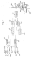
Die Erfindung wird im folgenden anhand schematischer Zeichnungen beispielsweise und mit weiteren Einzelheiten erläutert.The invention is explained below with reference to schematic drawings, for example and with further details.
Es stellen dar:
- Fig. 1 ein Schema einer mit Abgasturbolader ausgerüsteten Brennkraftmaschine,
- Fig. 2 ein Blockschaltbild einer ersten Ausführungsform der Ansteuerung eines Abblasventils und
- Fig. 3 ein Blockschaltbild einer zweiten Ausführungsform einer Ansteuerung des Abblasventils.
- 1 is a diagram of an internal combustion engine equipped with an exhaust gas turbocharger,
- Fig. 2 is a block diagram of a first embodiment of the control of a relief valve and
- Fig. 3 is a block diagram of a second embodiment of a control of the relief valve.
Gemäß Fig. 1 weist eine Brennkraftmaschine 6 mehrere Zylinder 8 auf, in denen nicht dargestellte Kolben arbeiten. Jeder Zylinder 8 ist über eine Saugleitung 10 mit einem Saugrohr 12 (durchgehend gezeichnet) und über eine Auslaßleitung 14 mit einem Abgaskrümmer 16 verbunden.1, an internal combustion engine 6 has a plurality of cylinders 8, in which pistons, not shown, work. Each cylinder 8 is connected via a
An den Abgastrummer 16 ist ein insgesamt mit 18 bezeichneter Abgasturbolader angeschlossen, der auf einer gemeinsamen Welle eine Abgasturbine 20 und eine Ladeturbine 22 aufweist. Von der Abgasturbine 20 führt ein Abgasrohr 24 zu einem Schalldämpfer 26 des Auspuffs der Brennkraftmaschine.An exhaust gas turbocharger, designated as a whole by 18, is connected to the
Der Auslaß der Ladeturbine 22 ist mit dem Saugrohr 12 verbunden. Im Einlaß in das Saugrohr 12 sitzt eine mit einem Gaspedal 28 zusammenwirkende Drosselklappe 30.The outlet of the
Am Einlaß oder Ladeturbine 22 ist eine Luftdurchsatzmeßeinrichtung 34 angeordnet, die den Durchsatz der von der Ladeturbine 22 durch ein Luftfilter 36 hindurch angesaugten Frischluft mißt. Die Luftdurchsatzmeßeinrichtung 34 arbeitet mit einer Einspritzanlage zusammen, mittels der in jede Saugleitung 10 eine dem Luftdurchsatz entsprechende Kraftstoffmenge eingespritzt wird.An air
An den Abgaskrümmer 16 ist über eine Verbindungsleitung 37 ein Abblasventil 38 angeschlossen, durch das hindurch die Abgase der Brennkraftmaschine 6 unter Umgehung der Abgasturbine 20 unmittelbar in das Abgasrohr 24 entweichen können. Dieses Abblasventil 38 weist ein Verschlußglied 40 mit einem Schaft 42 auf, welcher beispielsweise über eine Verzahnung mit einem Ritzel 44 eines Stellmotors 46 zusammenwirkt.A blow-off
Zur Messung des im Saugrohr 12 stromunterhalb der Drosselklappe 30 herrschenden Druckes ist ein Druckfühler 52 und zur Messung der im Saugrohr herrschenden Temperatur ein Temperaturfühler 54 vorgesehen. Zur Messung der Drehzahl der Brennkraftmaschine 6 ist ein Drehzahlmesser 56 vorgesehen. Klopfende Verbrennung läßt sich mit einem Klopfsensor 58 feststellen, der an einer geeigneten Stelle des Motorblocks der Brennkraftmaschine 6 befestigt ist. Zur Messung des Druckes im Saugrohr 12 stromoberhalb der Drcsselklappe 30 ist ein weiterer Druckfühler 60 vorg-e-sehen.A
Die Übertragung der Betätigung des Gaspedals 28 auf die Drosselklappe 30 erfolgt mittels eines Seilzuges 62, welcher über zwei ortsfeste Rollen 64 und 66 und ein drehbare Segmentscheibe 68 läuft, an welcher ein Stelluogsfühler 70 angebracht ist, der ein der Stellung der Drosselklappe 30 entsprechendes Signal abgibt. Zwischen dem Seilzug 62 und einem an der Drosselklappe befestigten Hebel ist eine erste Feder 72 angeordnet, welche stärker ist als eine zweite Feder 74, welche die Drosselklappe in Schließstellung zieht. Der an der Drosselklappe 30 befestigte Hebel liegt in voll geöffneter Stellung der Drosselklappe an einem Anschlag an, der gleichzeitig einen Schalter 76 bildet, welcher bei Betätigung des Gaspedals 28 über die voll geöffnete Stellung der Drosselklappe 30 hinaus schließt. In diesem Betätigungsbereich des Gaspedals 28 gibt der Stellungsfühler 70 somit ein Signal ab, welches ein Maß lediglich für die Betätigung des Gaspedals 28 ist.The transmission of the actuation of the
Fig. 2 zeigt ein Blockschaltbild der Zusammenschaltung der verschiedenen Fühler der Anordnung gemäß Fig. 1 mit dem Stellmotor 46:
- Die beiden
Druckfühler 52 und 60 sind mit den Eingängen einesDifferenzgliedes 80 verbunden, das die Differenz zwischen den bei den von denDruckfühlern 52 und 60 aufgenommenen Drucken bildet und ein entsprechendes Signal einem Eingang einesVergleichers 82 zuführt.
- The two
pressure sensors differential element 80, which forms the difference between the pressures recorded by thepressure sensors comparator 82.
Der Druckfühler 52 zur Messung des Druckes stromunterhalb der Drosselklappe 30 ist zusätzlich mit einem Eingang eines programmierbaren Speichers 84 verbunden, dessen andere Eingänge mit dem Drehzahlmesser 56, dem Stellungsfühler 70 und dem Temperaturfühler 54 verbunden sind. In dem Speicher 84 sind den Eingangswerten entsprechende Soll-Werte der Druckdifferenz stromunterhalb und stromoberhalb der Drosselklappe 30 gespeichert, welche dem anderen Eingang des Vergleichers 82 zugeführt werden.The
Der Drehzahlmesser 56, der Temperaturfühler 54 und der Klopfsensor 58 sind mit Eingängen eines weiteren Speichers 86 ver- bunden, in dem jeweils maximal zulässige Werte des Druckes stromunterhalb der Drosselklappe 30 gespeichert sind, welche in einem weiteren Vergleicher 88 mit den jeweiligen Ist-Werten des Drukkes stromunterhalb der Drosselklappe 30 verglichen werden.The
Ein weiterer Speicher 90, welcher mit dem Temperaturfühler 54, dem Stellungsfühler 70 und dem Drehzahlmesser 56 verbunden ist, tritt bei Schließen des Schalters 76 in Funktion und enthält Soll-Werte des Saugrohrdruckes, welche bei voll geöffneter Drosselklappe 30 in Abhängigkeit von der Saugrohrtemperatur, der Drehzahl der Brennkraftmaschine und der Stellung des Gaspedals 28 erreicht werden sollen. Entsprechend ist der Ausgang des Speichers 90 mit einem weiteren Vergleicher 92 verbunden, dem das Signal des Druckfühlers 60 zugeführt wird.Another
Der Ausgang des Vergleichers 82 ist mit einem ersten UND-Glied 94 verbunden, dessen anderer Eingang über einen Inverter 96 mit dem Schalter 76 und einem Eingang eines zweiten UND-Gliedes 98 verbunden ist, dessen anderer Eingang mit dem Vergleicher 92 verbunden ist.The output of the
Der Ausgang des ersten UND-Gliedes 94 ist mit einem Eingang eines dritten UND-Gliedes 100 verbunden, dessen anderer Eingang über einen Inverter 102 mit dem Vergleicher 88 verbunden ist. Der Ausgang des Inverters 102 ist ebenfalls mit einem Eingang eines vierten UND-Gliedes 104 verbunden, dessen anderer Eingang mit dem Ausgang des UND-Gliedes 98 verbunden ist.The output of the first AND
Die Eingänge eines ODER-Gliedes 106 sind mit dem Vergleicher 8e, dem dritten UND-Glied 100 und dem vierten UND-Glied 104 verbunden.The inputs of an OR gate 106 are connected to the comparator 8e, the third AND
Der Ausgang des ODER-Gliedes 106 ist über eine Steuerschaltung 108 mit dem Stellmotor 46 (Fig. 1) verbunden.The output of the OR gate 106 is connected to the servomotor 46 (FIG. 1) via a
Die Funktion der beschriebenen Schaltung ist folgende:
- Sei zunächst angenommen, daß die Brennkraftmaschine mit teilweise geöffneter Drosselklappe betrieben wird und der Druck im Saugrohr 12 stromab der Drosselklappe unter einem höchst zulässigen Druck liegt.
Der Vergleicher 88 liefert dann kein Signal, so daß das UND-Glied 100 durchlässig ist und das UND-Glied 98 gesperrt ist.
- First assume that the internal combustion engine is operated with the throttle valve partially open and the pressure in the intake manifold 12 downstream of the throttle valve is below a maximum permissible pressure. The
comparator 88 then delivers no signal, so that the ANDgate 100 is transparent and the ANDgate 98 is blocked.
Der Speicher 84 liefert einen Soll-Wert, welcher im Vergleicher 82 mit dem Ist-Wert der Differenz zwischen den Drücken stromoberhalb und stromunterhalb der Drosselklappe 30 verglichen wird. Das UND-Glied 94 ist wegen des Inverters 96 und des geöffneten Schalters 76 durchlässig, so daß das Ergebnis des Vergleichers durch das UND-Glied 100 und das ODER-Glied 106 hindurch zur Steuerschaltung 108 gelangt und dort eine Ansteuerung des Stellmotors 46 in Richtung einer Verringerung des Ergebnisses des Vergleichers 82 hervorruft. Ist die Differenz zwischen dem Druck stromoberhalb und dem Druck stromunterhalb der Drosselklappe 30 beispielsweise zu groß und liefert der Vergleicher 82 also ein positives Ausgangssignal, so betätigt die Steuerschaltung 108 den Stellmotor in Richtung einer Öffnung des Abblasventils 38, wodurch der Druck stromoberhalb der Drosselklappe sinkt.The
Steigt der Druck stromunterhalb der Drosselklappe 30 über einen bei der jeweiligen Drehzahl und der Saugrohrtemperatur der Brenn- .kraftmaschine höchst zulässigen Wert an, so gibt der Vergleicher 88 ein positives Signal ab, welches das UND-Glied 100 sperrt und über das ODER-Glied 106 die Steuerschaltung 108 ansteuert und zu einer zunehmenden Öffnung des Abblasventils führt. Ebenso wird der Vergleicher 88 bei klopfender Verbrennung aktiviert und öffnet das Abblasventil 38.If the pressure downstream of the throttle valve 30 rises above a value which is the maximum permissible at the respective speed and the intake manifold temperature of the internal combustion engine, the
Wird nun die Drosselklappe 30 voll geöffnet, so schließt der Schalter 76, wodurch das UND-Glied 94 sperrt und das UND-Glied 98 durchlässig wird. Bei einer Gasbetätigung über die voll geöffnete Stellung der Drosselklappe hinaus wird somit der Speicher 90 wirksam, wodurch die Steuerschaltung 108 nur noch in Abhängigkeit eines Vergleichers zwischen einem Soll-Wert des Saugrohrdruckes und einem vom Druckfühler 60 ermittelten Ist-Wert angesteuert wird. Bei voll geöffneter Stellung der Drosselklappe 30 und zunehmender Stellung des Gaspedals 28 erfolgt die Leistungssteuerung somit ausschließlich über das Abblasventil 38. Wird in diesem Zustand der höchst zulässige Saugrohrdruck überschritten oder tritt klopfende Verbrennung auf, so tritt wiederum der Vergleicher 88 in Aktion, wodurch das UND-Glied 104 sperrt und die Steuerschaltung 108unmittelbar vom Vergleischer 88 angesteuert wird.If the throttle valve 30 is now fully opened, the
Es versteht such, daß zahlreiche Abänderungen der beschiebenen Schaltung möglich sind, von denen im folgenden einige erläutert seien:
- Beispielsweise kann der Speicher 84 nur
mit dem Drehzahlmesser 56und dem Stellungsfühler 70 oder auch nurmit dem Drehzahlmesser 56und dem Druckfühler 52 verbunden sein und entsprechend nur von den Größen der jeweiligen Fühler abhängige Soll-Werte enthalten. Bei der ersten Abwandlung ergibt sich ein gleichmäßiger Betrieb der Brennkraftmaschine, bei der die Drosselklappenstellung nicht ständig korrigiert werden muß.Die im Speicher 84 gespeicherten Soll-Werte werden vorteilhafterweise im Hinblick auf minimalen Verbrauch der Brennkraftmaschine ermittelt.
- For example, the
memory 84 can only be connected to thetachometer 56 and theposition sensor 70 or also only to thetachometer 56 and thepressure sensor 52 and accordingly only contain desired values which are dependent on the sizes of the respective sensors. The first modification results in a smooth operation of the internal combustion engine, in which the throttle valve position does not have to be constantly corrected. The target values stored in thememory 84 are advantageously determined with regard to the minimum consumption of the internal combustion engine.
Die im Speicher 90 abgespeicherten Werte dagegen werden vorteilhafterweise im Hinblick auf zusammen mit zweckmäßigen Zündzeitpunkten optimale Leistung der Brennkraftmaschine ermittelt.The values stored in the
Der Temperaturfühler 54 kann zumindest wenn kein Ladeluftkühler vorgesehen ist, auch so angeordnet sein, daß er die jeweilige Temperatur der Außenluft, bzw. in den Lader eintretende Luft, mißt. Dadurch werden mögliche Selbstregeleffekte vermieden, die dadurch bedingt sind, daß die Temperatur im Saugrohr von der Komprimierung der Luft in der Ladeturbine 22 und der Expansion beim Umströmen der Drosselklappe 30 abhängt.The
Der Klopfsensor 58 kann den Speicher 86 überflüssig machen und mit höchster Priorität die Steuerschaltung 108 unmittelbar ansteuern.
Im Leerlauf der Brennkraftmaschine, d.h. bei geschlossener Drosselklappe ist das Abblasventil 38 vorteilhafterweise vollständig geschlossen, was mittels eines unmittelbar von der Drosselklappe betätigten Schalters erreicht werden kann.With the engine idling, i.e. when the throttle valve is closed, the blow-off
Die Drosselklappe 30 kann vollelektronisch entsprechend im Speicher 84 gespeicherten Werten betätigt sein. In diesem Falle kann die mechanische Verbindung zwischen Gaspedal 28 und Drosselklap- |pe 30 entfallen.The throttle valve 30 can be actuated fully electronically in accordance with values stored in the
Zur Betätigung dr's Abblasventils 38 muß nicht notwenigerweise ein elektrischer Stellmotor 46 vorgesehen sein. Vorteilhaft ist eine Betätigung mittels eines pneumatischen oder hydraulischen Stellmotors, welcher schwingungsunempfindlicher ist bzw. in sener Montage freier wählbar ist.For actuating dr 's bleed
Bei hydraulischer Betätigung kann als Arbeitsmittel Motoröl oder Flüssigkeit verwendet werden, welche von einem hydraulischen Hilfsantrieb abgezweigt wird, beispielsweise einer hydraulischen Lenkhilfeeinrichtung.With hydraulic actuation, engine oil or liquid can be used as the working medium, which is branched off by a hydraulic auxiliary drive, for example a hydraulic steering aid device.
Der Vergleicher 82 ist bei dieser Ausführungsform an einen Zähler 110 angeschlossen, dessen Ausgang mit einem Vergleicher 112 verbunden ist. Ein weiterer Eingang des Vergleichers 112 ist mit einem Ringzähler 114 verbunden, der über eine Rücksetzleitung 116 jeweils auf Null zurückspringt, wenn er seinen maximalen Zählstand erreicht hat. Zur Ansteuerung der Zähler 110 und 114 ist ein Taktgeber 117 vorgesehen.In this embodiment, the
Der Ausgang des Vergleichers 112 ist mit einem Magnetventil 118 verbunden, das in einer mit konstantem Druckmitteldruck beaufschlagten Leitung 120 sitzt. Stromab des Magnetventils 118 ist eine AbströmleiTung 122 mit einer Drossel 124 vorgesehen. Mit dem Druck stromab des Magnetventils 118 ist ein Arbeitsraum 126 beaufschlagt, in dem gegen die Kraft einer Feder 128 ein Kolben arbeitet, der mit dem Schaft 42 des Abblasventils 38 verbunden ist.The output of the
Die Funktion der einzelnen, in ihrem Aufbau an sich bekannten Bauteile ist folgende:
Der Zähler 110,der vom Taktgeber 117 angesteuert wird, erhöht mit jedem Takt seinen Zählstand bei einem positiven Ausgang des Vergleichers 82 und vermindert seinen Zählstand bei einem negativen Ausgang desVergleichers 82.
- The
counter 110, which is driven by theclock generator 117, increases its count with a positive output of thecomparator 82 with every clock and decreases its count with a negative output of thecomparator 82.
Der Zähler 114 wird mit einer wesentlich größeren Taktfrequenz angesteuert als der Zähler 110.The
Der Vergleicher 112 öffnet das Magnetventil 118, wenn der Zähl- stand des Zählers 114 größer als der Zählstand des Zählers 110 ist.The
Die Funktion der gesamten Schaltung ist folgende:
- Es sei angenommen, daß die Differenz zwischen dem Druck stromoberhalb und stromunterhalb der Drosselklappe 30 zu groß ist, der Vergleicher 82 also ein positives Ausgangssignal erzeugt.
Der Zähler 110 erhöht dann seinen Zählstand, so daß die Zeitdauer, während der der Zählstand desZählers 114 größer ist als der Zählstand desZählers 110 abnimmt. Dies führt dazu, daß die Zeitdauer, während derdas Magnetventil 118vom Vergleicher 112 aus geöffnet wird, abnimmt. Der Druck stromab desMagnetventils 118 sinkt dadurch,wodurch das Abblasventil 38 zunehmend geöffnet wird, abnimmt. Der Druck stromab desMagnetventils 118 sinkt dadurch,wodurch das Abblasventil 38 zunehmend geöffnet wird und die Druckdifferenz stromoberhalb und stromunterhalb der Drosselklappe abnimmt.
- It is assumed that the difference between the pressure upstream and downstream of the throttle valve 30 is too great, that is to say the
comparator 82 generates a positive output signal. Thecounter 110 then increments its count so that the length of time during which the count of thecounter 114 is greater than the count of thecounter 110 decreases. As a result, the length of time during which thesolenoid valve 118 is opened from thecomparator 112 decreases. As a result, the pressure downstream of thesolenoid valve 118 drops, as a result of which the blow-offvalve 38 is increasingly opened and decreases. As a result, the pressure downstream of thesolenoid valve 118 drops, as a result of which the blow-offvalve 38 is opened increasingly and the pressure difference decreases upstream and downstream of the throttle valve.
Es versteht sich, daß die Anordnung gemäß Fgi. 3 entsprechend der Anordnung gemäß Fig. 2 durch die Schaltungsteile ergänzt werden kann, welche bei unzulässig hohem Saugrohrdruck, klopfender Verbrennung bzw. voll geöffneter Drosselklappe wirksam werden.It is understood that the arrangement according to Fgi. 3 can be supplemented in accordance with the arrangement according to FIG. 2 by the circuit parts which become effective when the intake manifold pressure is inadmissibly high, knocking combustion or the throttle valve is fully open.
Auch kann das Magnetventil 118 in der Abströmleitung 122 und die Drossel 124 in der Leitung 120 angeordnet sein. Bei dieser Ausführungsform kann das Abblasventil 38 durch Öffnen des Magnetventils 116 besonders rasch geöffnet werden.The
Claims (4)
Applications Claiming Priority (2)
| Application Number | Priority Date | Filing Date | Title |
|---|---|---|---|
| DE3032218A DE3032218C2 (en) | 1980-08-27 | 1980-08-27 | Piston internal combustion engine with an exhaust gas turbocharger |
| DE3032218 | 1980-08-27 |
Publications (3)
| Publication Number | Publication Date |
|---|---|
| EP0046872A2 true EP0046872A2 (en) | 1982-03-10 |
| EP0046872A3 EP0046872A3 (en) | 1982-09-08 |
| EP0046872B1 EP0046872B1 (en) | 1985-04-24 |
Family
ID=6110470
Family Applications (1)
| Application Number | Title | Priority Date | Filing Date |
|---|---|---|---|
| EP81105779A Expired EP0046872B1 (en) | 1980-08-27 | 1981-07-22 | Combustion piston engine with exhaust gas turbocharger |
Country Status (3)
| Country | Link |
|---|---|
| EP (1) | EP0046872B1 (en) |
| JP (1) | JPS5773824A (en) |
| DE (1) | DE3032218C2 (en) |
Cited By (14)
| Publication number | Priority date | Publication date | Assignee | Title |
|---|---|---|---|---|
| EP0111196A1 (en) * | 1982-12-14 | 1984-06-20 | FIAT AUTO S.p.A. | A regulation device for a turbo compressor unit for supercharging an internal combustion engine |
| US4594668A (en) * | 1983-02-16 | 1986-06-10 | Allied Corporation | Turbocharger control system |
| US4660382A (en) * | 1984-02-29 | 1987-04-28 | Nissan Motor Co., Ltd. | Device for controlling the supercharging pressure of a turbocharger |
| EP0227476A1 (en) * | 1985-12-24 | 1987-07-01 | AlliedSignal Inc. | Turbocharger system with electronic control |
| US4709553A (en) * | 1984-09-05 | 1987-12-01 | Nissan Motor Co., Ltd. | Method of and apparatus for controlling supercharge pressure for a turbocharger |
| EP0253075A1 (en) * | 1986-07-12 | 1988-01-20 | Dr.Ing.h.c. F. Porsche Aktiengesellschaft | Multicylinder internal combustion engine with two exhaust gas turbochargers |
| WO1989011027A1 (en) * | 1988-05-07 | 1989-11-16 | Robert Bosch Gmbh | Control of supercharged internal combustion engines |
| EP0829632A3 (en) * | 1996-09-03 | 1998-11-25 | Dresser Industries Inc. | Electronically controlled wastegate valve |
| WO1999053183A1 (en) * | 1998-04-15 | 1999-10-21 | Caterpillar Inc. | An apparatus and method for controlling the air flow into an engine |
| EP1026378A2 (en) * | 1999-02-02 | 2000-08-09 | Waukesha Engine Division, Dresser Equipment Group, Inc. | Turbocharger control management system and throttle reserve control |
| GB2372839A (en) * | 1998-05-27 | 2002-09-04 | Cummins Engine Co Inc | Method for controlling an i.c. engine turbocharger using a lookup table |
| KR101126935B1 (en) * | 2003-12-05 | 2012-03-20 | 모멘티브 파포만스 마테리아루즈 쟈판 고도가이샤 | Cosmetic hair composition |
| WO2014094807A1 (en) * | 2012-12-21 | 2014-06-26 | Caterpillar Energy Solutions Gmbh | Control system for internal combustion engines |
| US20150059338A1 (en) * | 2013-08-29 | 2015-03-05 | Ford Global Technologies, Llc | Determination of wastegate valve position |
Families Citing this family (7)
| Publication number | Priority date | Publication date | Assignee | Title |
|---|---|---|---|---|
| SE458290B (en) * | 1981-02-19 | 1989-03-13 | Volvo Ab | DEVICE FOR CONTROL OF CHARGING PRESSURE IN A TURBOLED FORMING ENGINE |
| DE3303350C2 (en) * | 1983-02-02 | 1994-10-13 | Bosch Gmbh Robert | Control device for the boost pressure of an internal combustion engine with a turbocharger |
| JPS6116231A (en) * | 1984-07-04 | 1986-01-24 | Mazda Motor Corp | Supercharging pressure controller for supercharged engine |
| DE3623541A1 (en) * | 1986-07-12 | 1988-02-11 | Porsche Ag | INTERNAL COMBUSTION ENGINE WITH AT LEAST ONE TURBOCHARGER |
| JP2550461Y2 (en) * | 1991-09-03 | 1997-10-15 | ユニ・チャーム株式会社 | Disposable diapers |
| DE102004031230A1 (en) * | 2004-06-29 | 2006-01-19 | Audi Ag | Load pressure control device for internal combustion engines with superchargers has mechanical rule member connected to electric motor and arranged in exhaust bypass line |
| DE102011103518A1 (en) | 2011-06-07 | 2012-12-13 | Mtu Friedrichshafen Gmbh | Blow-off valve for turbine of exhaust gas turbocharger mounted in internal combustion engine, has cam gear which converts rotational movement of drive element to translational movement of valve plate |
Citations (8)
| Publication number | Priority date | Publication date | Assignee | Title |
|---|---|---|---|---|
| DE2716470A1 (en) * | 1977-04-14 | 1978-10-19 | Daimler Benz Ag | COMBUSTION ENGINE WITH AN EXHAUST GAS TURBOCHARGER |
| DE2823067A1 (en) * | 1977-05-26 | 1978-12-14 | Nissan Motor | RELIEF CONTROL FOR A TURBOCHARGER |
| FR2401313A1 (en) * | 1977-08-24 | 1979-03-23 | Nissan Motor | MOTOR VEHICLE EQUIPPED WITH A TURBINE BOOSTERING DEVICE |
| DE2745153A1 (en) * | 1977-10-07 | 1979-04-12 | Audi Nsu Auto Union Ag | Turbocharged engine intake pressure regulation system - has exhaust discharge valve opening at decreasing pressure with increasing speed |
| US4174617A (en) * | 1977-08-08 | 1979-11-20 | Jalali Karchay Mir Javid | Turbocharger control system |
| DE2835452A1 (en) * | 1978-08-12 | 1980-02-28 | Bernd Payrhammer | Control for turbocharged IC engine - has charge pressure varied as function of engine speed by speed-dependent pressure relief valve |
| JPS5529033A (en) * | 1978-08-18 | 1980-03-01 | Hitachi Ltd | Turbocharger controller |
| GB2034402A (en) * | 1978-11-18 | 1980-06-04 | Nissan Motor | Exhaust bypass valve assembly of an exhaust gas turbo-supercharged ic engine |
-
1980
- 1980-08-27 DE DE3032218A patent/DE3032218C2/en not_active Expired
-
1981
- 1981-07-22 EP EP81105779A patent/EP0046872B1/en not_active Expired
- 1981-08-27 JP JP56134789A patent/JPS5773824A/en active Pending
Patent Citations (8)
| Publication number | Priority date | Publication date | Assignee | Title |
|---|---|---|---|---|
| DE2716470A1 (en) * | 1977-04-14 | 1978-10-19 | Daimler Benz Ag | COMBUSTION ENGINE WITH AN EXHAUST GAS TURBOCHARGER |
| DE2823067A1 (en) * | 1977-05-26 | 1978-12-14 | Nissan Motor | RELIEF CONTROL FOR A TURBOCHARGER |
| US4174617A (en) * | 1977-08-08 | 1979-11-20 | Jalali Karchay Mir Javid | Turbocharger control system |
| FR2401313A1 (en) * | 1977-08-24 | 1979-03-23 | Nissan Motor | MOTOR VEHICLE EQUIPPED WITH A TURBINE BOOSTERING DEVICE |
| DE2745153A1 (en) * | 1977-10-07 | 1979-04-12 | Audi Nsu Auto Union Ag | Turbocharged engine intake pressure regulation system - has exhaust discharge valve opening at decreasing pressure with increasing speed |
| DE2835452A1 (en) * | 1978-08-12 | 1980-02-28 | Bernd Payrhammer | Control for turbocharged IC engine - has charge pressure varied as function of engine speed by speed-dependent pressure relief valve |
| JPS5529033A (en) * | 1978-08-18 | 1980-03-01 | Hitachi Ltd | Turbocharger controller |
| GB2034402A (en) * | 1978-11-18 | 1980-06-04 | Nissan Motor | Exhaust bypass valve assembly of an exhaust gas turbo-supercharged ic engine |
Non-Patent Citations (2)
| Title |
|---|
| Automotive Engineering, Band 88, Nr. 7, Juli 1980, New York "Automatic Anti-Knock for Turbocharger" seite 95 * |
| PATENT ABSTRACTS OF JAPAN Band 4, Nr. 64, 14 Mai 1980 seite 38M11 & JP-A-55 029 033 * |
Cited By (19)
| Publication number | Priority date | Publication date | Assignee | Title |
|---|---|---|---|---|
| EP0111196A1 (en) * | 1982-12-14 | 1984-06-20 | FIAT AUTO S.p.A. | A regulation device for a turbo compressor unit for supercharging an internal combustion engine |
| US4594668A (en) * | 1983-02-16 | 1986-06-10 | Allied Corporation | Turbocharger control system |
| US4660382A (en) * | 1984-02-29 | 1987-04-28 | Nissan Motor Co., Ltd. | Device for controlling the supercharging pressure of a turbocharger |
| US4709553A (en) * | 1984-09-05 | 1987-12-01 | Nissan Motor Co., Ltd. | Method of and apparatus for controlling supercharge pressure for a turbocharger |
| EP0227476A1 (en) * | 1985-12-24 | 1987-07-01 | AlliedSignal Inc. | Turbocharger system with electronic control |
| EP0253075A1 (en) * | 1986-07-12 | 1988-01-20 | Dr.Ing.h.c. F. Porsche Aktiengesellschaft | Multicylinder internal combustion engine with two exhaust gas turbochargers |
| US4781027A (en) * | 1986-07-12 | 1988-11-01 | Dr. Ing.H.C.F. Porsche Aktiengesellschaft | Multi-cylinder internal combustion engine with two exhaust gas turbochargers |
| WO1989011027A1 (en) * | 1988-05-07 | 1989-11-16 | Robert Bosch Gmbh | Control of supercharged internal combustion engines |
| EP0829632A3 (en) * | 1996-09-03 | 1998-11-25 | Dresser Industries Inc. | Electronically controlled wastegate valve |
| WO1999053183A1 (en) * | 1998-04-15 | 1999-10-21 | Caterpillar Inc. | An apparatus and method for controlling the air flow into an engine |
| US6055811A (en) * | 1998-04-15 | 2000-05-02 | Caterpillar, Inc. | Apparatus and method for controlling the air flow into an engine |
| GB2372839A (en) * | 1998-05-27 | 2002-09-04 | Cummins Engine Co Inc | Method for controlling an i.c. engine turbocharger using a lookup table |
| GB2372839B (en) * | 1998-05-27 | 2002-12-04 | Cummins Engine Co Inc | System and method for controlling a turbocharger |
| EP1026378A2 (en) * | 1999-02-02 | 2000-08-09 | Waukesha Engine Division, Dresser Equipment Group, Inc. | Turbocharger control management system and throttle reserve control |
| EP1026378A3 (en) * | 1999-02-02 | 2001-11-07 | Waukesha Engine Division, Dresser Equipment Group, Inc. | Turbocharger control management system and throttle reserve control |
| KR101126935B1 (en) * | 2003-12-05 | 2012-03-20 | 모멘티브 파포만스 마테리아루즈 쟈판 고도가이샤 | Cosmetic hair composition |
| WO2014094807A1 (en) * | 2012-12-21 | 2014-06-26 | Caterpillar Energy Solutions Gmbh | Control system for internal combustion engines |
| US20150059338A1 (en) * | 2013-08-29 | 2015-03-05 | Ford Global Technologies, Llc | Determination of wastegate valve position |
| US9316147B2 (en) * | 2013-08-29 | 2016-04-19 | Ford Global Technologies, Llc | Determination of wastegate valve position |
Also Published As
| Publication number | Publication date |
|---|---|
| EP0046872A3 (en) | 1982-09-08 |
| DE3032218C2 (en) | 1982-06-16 |
| JPS5773824A (en) | 1982-05-08 |
| EP0046872B1 (en) | 1985-04-24 |
| DE3032218A1 (en) | 1982-03-25 |
Similar Documents
| Publication | Publication Date | Title |
|---|---|---|
| EP0046872B1 (en) | Combustion piston engine with exhaust gas turbocharger | |
| DE3203952C2 (en) | Internal combustion engine with a supercharging compressor | |
| DE3636642A1 (en) | CHARGING SYSTEM FOR MOTOR VEHICLE ENGINES | |
| DE112005001946T5 (en) | Opening / closing control of an inlet and outlet connection circuit | |
| DE10232337B4 (en) | Method and device for monitoring an air mass measuring device | |
| DE102009009843A1 (en) | Outlet flap control system based on variable valve actuation | |
| DE102014213631A1 (en) | Control device for internal combustion engines in a turbocharger | |
| DE102010043897B4 (en) | Method and device for operating an internal combustion engine | |
| DE10247428A1 (en) | Variable displacement charging system and method for detecting an abnormality in the charging system | |
| DE3246483C2 (en) | Control device for a turbine bypass valve of an exhaust gas-charged internal combustion engine | |
| DE10054843B4 (en) | Method for limiting the boost pressure | |
| DE3246855C2 (en) | Charge control device for internal combustion engines | |
| EP2923073B1 (en) | Method of operating a spark-ignition engine having a turbocharger | |
| DE4024572A1 (en) | Internal combustion engine for utility vehicle - has two exhaust turbo-superchargers either of which can be closed independently by controller of compressor output and air flow regulator | |
| DE3026150C2 (en) | ||
| EP0414781B1 (en) | Multicylinder internal-combustion engine | |
| DE3539782A1 (en) | Turbocharger system | |
| DE102008048679B4 (en) | Method for controlling and / or regulating a boost pressure of an exhaust gas turbocharger and an internal combustion engine | |
| EP2562381A1 (en) | Method for controlling the boost pressure in an internal combustion engine with a pressure wave supercharger | |
| DE4107693C2 (en) | System for regulating and controlling a loader | |
| DE3005108A1 (en) | Exhaust gas driven turbocharger for IC engine - has motor operated exhaust gas by=pass valve with automatic controller | |
| EP3591185A1 (en) | Method for operating a combustion engine with a trim adjuster assigned to the compressor | |
| DE69722632T2 (en) | INTERNAL COMBUSTION ENGINE WITH EXHAUST GAS RECIRCULATION | |
| EP3803086B1 (en) | Method for operating an internal combustion engine, and corresponding internal combustion engine | |
| DE3610131A1 (en) | Internal combustion engine, especially diesel engine, as drive unit for vehicles |
Legal Events
| Date | Code | Title | Description |
|---|---|---|---|
| PUAI | Public reference made under article 153(3) epc to a published international application that has entered the european phase |
Free format text: ORIGINAL CODE: 0009012 |
|
| AK | Designated contracting states |
Designated state(s): FR GB SE |
|
| PUAL | Search report despatched |
Free format text: ORIGINAL CODE: 0009013 |
|
| AK | Designated contracting states |
Designated state(s): FR GB SE |
|
| 17P | Request for examination filed |
Effective date: 19820810 |
|
| GRAA | (expected) grant |
Free format text: ORIGINAL CODE: 0009210 |
|
| AK | Designated contracting states |
Designated state(s): FR GB SE |
|
| ET | Fr: translation filed | ||
| RAP2 | Party data changed (patent owner data changed or rights of a patent transferred) |
Owner name: AUDI AG |
|
| PLBE | No opposition filed within time limit |
Free format text: ORIGINAL CODE: 0009261 |
|
| STAA | Information on the status of an ep patent application or granted ep patent |
Free format text: STATUS: NO OPPOSITION FILED WITHIN TIME LIMIT |
|
| 26N | No opposition filed | ||
| PGFP | Annual fee paid to national office [announced via postgrant information from national office to epo] |
Ref country code: SE Payment date: 19920715 Year of fee payment: 12 |
|
| PG25 | Lapsed in a contracting state [announced via postgrant information from national office to epo] |
Ref country code: SE Effective date: 19930723 |
|
| EUG | Se: european patent has lapsed |
Ref document number: 81105779.3 Effective date: 19940210 |
|
| PGFP | Annual fee paid to national office [announced via postgrant information from national office to epo] |
Ref country code: GB Payment date: 19950616 Year of fee payment: 15 |
|
| PGFP | Annual fee paid to national office [announced via postgrant information from national office to epo] |
Ref country code: FR Payment date: 19950712 Year of fee payment: 15 |
|
| PG25 | Lapsed in a contracting state [announced via postgrant information from national office to epo] |
Ref country code: GB Effective date: 19960722 |
|
| GBPC | Gb: european patent ceased through non-payment of renewal fee |
Effective date: 19960722 |
|
| PG25 | Lapsed in a contracting state [announced via postgrant information from national office to epo] |
Ref country code: FR Effective date: 19970328 |
|
| REG | Reference to a national code |
Ref country code: FR Ref legal event code: ST |