EP0046246A2 - Device for the removal of hydrogen from the safety containment structure of a nuclear reactor - Google Patents
Device for the removal of hydrogen from the safety containment structure of a nuclear reactor Download PDFInfo
- Publication number
- EP0046246A2 EP0046246A2 EP81106179A EP81106179A EP0046246A2 EP 0046246 A2 EP0046246 A2 EP 0046246A2 EP 81106179 A EP81106179 A EP 81106179A EP 81106179 A EP81106179 A EP 81106179A EP 0046246 A2 EP0046246 A2 EP 0046246A2
- Authority
- EP
- European Patent Office
- Prior art keywords
- hydrogen
- gas mixture
- safety container
- wall
- housing
- Prior art date
- Legal status (The legal status is an assumption and is not a legal conclusion. Google has not performed a legal analysis and makes no representation as to the accuracy of the status listed.)
- Granted
Links
- UFHFLCQGNIYNRP-UHFFFAOYSA-N Hydrogen Chemical compound [H][H] UFHFLCQGNIYNRP-UHFFFAOYSA-N 0.000 title claims abstract description 20
- 239000001257 hydrogen Substances 0.000 title claims abstract description 17
- 229910052739 hydrogen Inorganic materials 0.000 title claims abstract description 17
- 239000000203 mixture Substances 0.000 claims abstract description 38
- 239000007789 gas Substances 0.000 claims abstract description 35
- 230000006698 induction Effects 0.000 claims abstract description 11
- 238000004804 winding Methods 0.000 claims abstract description 11
- 238000010438 heat treatment Methods 0.000 claims description 10
- 238000009413 insulation Methods 0.000 claims description 2
- 238000009434 installation Methods 0.000 abstract 1
- 238000001816 cooling Methods 0.000 description 3
- 238000006243 chemical reaction Methods 0.000 description 2
- 238000002485 combustion reaction Methods 0.000 description 2
- 230000008878 coupling Effects 0.000 description 2
- 238000010168 coupling process Methods 0.000 description 2
- 238000005859 coupling reaction Methods 0.000 description 2
- 230000002285 radioactive effect Effects 0.000 description 2
- 230000003068 static effect Effects 0.000 description 2
- 238000009825 accumulation Methods 0.000 description 1
- 230000015572 biosynthetic process Effects 0.000 description 1
- 239000002826 coolant Substances 0.000 description 1
- 238000005202 decontamination Methods 0.000 description 1
- 230000003588 decontaminative effect Effects 0.000 description 1
- 238000004200 deflagration Methods 0.000 description 1
- 238000007865 diluting Methods 0.000 description 1
- 230000000694 effects Effects 0.000 description 1
- 238000004880 explosion Methods 0.000 description 1
- 238000011010 flushing procedure Methods 0.000 description 1
- 230000001939 inductive effect Effects 0.000 description 1
- 239000007788 liquid Substances 0.000 description 1
- 238000002156 mixing Methods 0.000 description 1
- 229910001220 stainless steel Inorganic materials 0.000 description 1
- 239000010935 stainless steel Substances 0.000 description 1
- XLYOFNOQVPJJNP-UHFFFAOYSA-N water Substances O XLYOFNOQVPJJNP-UHFFFAOYSA-N 0.000 description 1
Images
Classifications
-
- G—PHYSICS
- G21—NUCLEAR PHYSICS; NUCLEAR ENGINEERING
- G21C—NUCLEAR REACTORS
- G21C19/00—Arrangements for treating, for handling, or for facilitating the handling of, fuel or other materials which are used within the reactor, e.g. within its pressure vessel
- G21C19/28—Arrangements for introducing fluent material into the reactor core; Arrangements for removing fluent material from the reactor core
- G21C19/30—Arrangements for introducing fluent material into the reactor core; Arrangements for removing fluent material from the reactor core with continuous purification of circulating fluent material, e.g. by extraction of fission products deterioration or corrosion products, impurities, e.g. by cold traps
-
- G—PHYSICS
- G21—NUCLEAR PHYSICS; NUCLEAR ENGINEERING
- G21D—NUCLEAR POWER PLANT
- G21D1/00—Details of nuclear power plant
- G21D1/02—Arrangements of auxiliary equipment
-
- Y—GENERAL TAGGING OF NEW TECHNOLOGICAL DEVELOPMENTS; GENERAL TAGGING OF CROSS-SECTIONAL TECHNOLOGIES SPANNING OVER SEVERAL SECTIONS OF THE IPC; TECHNICAL SUBJECTS COVERED BY FORMER USPC CROSS-REFERENCE ART COLLECTIONS [XRACs] AND DIGESTS
- Y02—TECHNOLOGIES OR APPLICATIONS FOR MITIGATION OR ADAPTATION AGAINST CLIMATE CHANGE
- Y02E—REDUCTION OF GREENHOUSE GAS [GHG] EMISSIONS, RELATED TO ENERGY GENERATION, TRANSMISSION OR DISTRIBUTION
- Y02E30/00—Energy generation of nuclear origin
- Y02E30/30—Nuclear fission reactors
Definitions
- the invention relates to a device for removing hydrogen gas from the safety container of a nuclear reactor system using a thermal recombiner, which consists of a metallic housing and baffles for the gas flow arranged therein, and has a supply line for the hydrogen-enriched gas mixture and a discharge line for the hydrogen-poor gas mixture. ,
- the gas mixture is heated and reached via the hot room air then in the reaction chamber, which is also located in this room.
- the now low-hydrogen gas mixture leaves the insulated room via a pipe and, after it has released its residual heat to a heat exchanger, returns to the safety container.
- This type of heating requires a large amount of space.
- the device can only be operated if the hydrogen content of the gas mixture introduced is below the lower explosion limit of 4% by volume.
- the object of the invention is therefore to provide a device of the type mentioned at the outset, which has a compact heating device and allows the safe processing of all gas mixture concentrations.
- the object is achieved in that the wall of the housing and the baffle plates are inductively heated and that the supply line for the hydrogen-enriched gas mixture is connected to the discharge line for the hydrogen-poor gas mixture via a three-way valve, the third outlet of which leads part of the low-hydrogen gas mixture to the safety container .
- the housing of the recombiner is preferably an elongated tubular body the at least partially by one is surrounded.
- the area of the housing wall surrounded by the induction winding is reinforced and the deflection plates contact the inside of the wall in a kind of frictional connection.
- a similar effect is achieved in that the baffle plates are welded to a thick-walled pipe section and the pipe section forms the frictional connection on the circumferential side with the inside of the housing wall.
- the gas flowing in the connecting line between the three-way valve and the safety container and in the supply line in the area between the safety container and a recuperative heat exchanger is preferably kept at a temperature which is higher than the temperature prevailing in the safety container by means of a trace heating.
- a trace heating This measure has the advantage that there is no formation of condensate in the line system and therefore no highly radioactive condensate is produced outside the containment.
- the trace heating also absorbs the water produced during the combustion of the hydrogen by the low-hydrogen gas mixture.
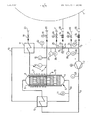
- the device is described using an exemplary embodiment and a schematic drawing.
- Hydrogen-enriched gas mixture which has formed there in an impermissible enrichment, is removed from the safety container 1 of a nuclear reactor system (not shown further) with the aid of the blower 2 and the feed line 3 and fed into the recombiner 4.
- the housing 5 of the recombiner is a cylindrical, elongated tubular body which is hemispherically closed at both ends.
- Deflection plates 6 made of stainless steel are arranged in the cylindrical part of the housing and serve as static mixing elements.
- the upper half of the housing is covered by a water-cooled winding 7 heated inductively. The eddy currents are induced not only in the housing wall 8 but also in the deflection plates 6, so that a homogeneous temperature distribution is ensured.
- Insulation 13 attached to the cylindrical part of the housing 5 simultaneously protects the induction winding from excessive heat load.
- the self-heating of the induction winding is released via a cooling circuit 14.
- the cooling circuit is equipped with measuring points 15, 16, a recuperative heat exchanger 17, a shut-off valve 18 and a control valve 19. It is connected to a line system, not shown, via quick-action couplings 20.
- the deflection plates 6 are welded to a thick-walled tube piece 9, which enters into a kind of frictional connection on the circumference and contacts the inside of the housing wall 8. Durr: h this intimate connection, an effective heat input is achieved.
- the upper half of the recombiner is used to heat up to the operating temperature of 700-750 ° C.
- the residence time of the hot gas mixture for the complete reaction is approx. 0.5 seconds.
- a homogeneous temperature distribution is achieved by appropriate design of the baffle plates. With a throughput of 180 m 3 / h (iN) for a total residence time of 1 sec. a total of approx. 50 liters total volume of the recombiner is required. This volume is achieved, for example, by a housing 5 which consists of a 1500 mm long pipe with a nominal diameter of 250 mm. Following the combustion of the now low-hydrogen gas mixture to R ekombinator leaves via the discharge line 10. With the aid of the temperature measuring point 11, the necessary heating capacity of the induction coil 7 is controlled. The gas mixture releases part of its heat when flowing through a recuperative heat exchanger 12.
- the gas mixture flowing in the feed line 3 is preheated.
- the gas mixture located in the discharge line 3 is cooled to 60 to 65 ° C. in the recuperative heat exchanger 17.
- the gas mixture cooled to this point now arrives at a remotely controllable three-way valve 21. From here, the major part of the low-hydrogen gas mixture flows via the outlet 22 of the three-way valve and the line 23 through a flame arrester 34 back to the safety container 1.
- the remaining rest of the gas mixture reaches the connecting line 3a to the feed line 3 and serves to dilute the hydrogen-enriched gas mixture brought in by the containment.
- the amount of the gas mixture brought in by the connecting line 3a depends on the hydrogen content of the gas mixture brought in from the containment. It is controlled via the three-way valve so that the gas mixture leading to the recombiner is always below 4% by volume of hydrogen. A dangerous deflagration is thus prevented with certainty.
- Flow measuring devices 27, 28, pressure measuring devices 29, 30, 31, temperature sensors 32, 33 and a flame arrester 34 are installed in the supply line 3 and the connecting line 3a.
- the line 23 is heated via a trace heater (not shown) in order to keep the gas mixture at a temperature of 60-65 ° C.
- the area of the supply line 3 between the safety container 1 and the recuperative heat exchanger 12 is also provided with a trace heating, not shown.
- the temperature of the gas mixture flowing therein is thereby kept at a higher value than the temperature measured inside the containment.
- this measure is intended to avoid any highly radioactive condensate accumulation outside the containment.
Landscapes
- Physics & Mathematics (AREA)
- Engineering & Computer Science (AREA)
- Plasma & Fusion (AREA)
- General Engineering & Computer Science (AREA)
- High Energy & Nuclear Physics (AREA)
- Structure Of Emergency Protection For Nuclear Reactors (AREA)
Abstract
Description
Die Erfindung betrifft eine Einrichtung zur Entfernung von Wasserstoffgas aus dem Sicherheitsbehälter einer Kernreaktoranlage unter Verwendung eines thermischen Rekombinators,der aus einem metallischen Gehäuse und darin angeordneten Umlenkblechen für den Gasstrom besteht sowie eine Zufuhrleitung für das wasserstoffangereicherte Gasgemisch und eine Abfuhrleitung für das wasserstoffarme Gasgemisch aufweist. ,The invention relates to a device for removing hydrogen gas from the safety container of a nuclear reactor system using a thermal recombiner, which consists of a metallic housing and baffles for the gas flow arranged therein, and has a supply line for the hydrogen-enriched gas mixture and a discharge line for the hydrogen-poor gas mixture. ,
Eine ähnliche Einrichtung ist aus der Druckschrift "Hydrogen Rekombiner System" der Firma Rockwell unter der Publication Nr. 523K-20 Rev.8.79 bekannt geworden. Dabei sind in einem isolierten Raum zwei elektrische Heizelemente angeordnet. Innerhalb dieses Raumes strömt das aus dem Sicherheitsbehälter herangeführte wasserstoffangereicherte Gasgemisch in einer großen Rohrspirale.A similar device is known from the publication "Hydrogen Rekombiner System" from Rockwell under publication no. 523K-20 Rev.8.79. Two electrical heating elements are arranged in an insulated room. Within this room, the hydrogen-enriched gas mixture that flows out of the safety container flows in a large spiral pipe.
Über die heiße Raumluft wird das Gasgemisch erwärmt und gelangt dann in den ebenfalls in diesem Raum angeordneten Reaktionskammer. Das nunmehr wasserstoffarme Gasgemisch verläßt über eine Leitung den isolierten Raum und gelangt, nachdem es seine Restwärme an einen Wärmetauscher abgegeben hat, wieder in den Sicherheitsbehälter. Diese Art der Beheizung erfordert einen großen Platzbedarf. Außerdem kann aus Sicherheitsgründen die Einrichtung nur betrieben werden, wenn der Wasserstoffgehalt des herangeführten Gasgemisches unter der unteren Explosionsgrenze von 4 Vol.% liegt.The gas mixture is heated and reached via the hot room air then in the reaction chamber, which is also located in this room. The now low-hydrogen gas mixture leaves the insulated room via a pipe and, after it has released its residual heat to a heat exchanger, returns to the safety container. This type of heating requires a large amount of space. In addition, for safety reasons, the device can only be operated if the hydrogen content of the gas mixture introduced is below the lower explosion limit of 4% by volume.
Die Erfindung stellt sich daher die Aufgabe eine Einrichtung der eingangs genannten Art anzugeben, die eine kompakte Heizeinrichtung aufweist und die gefahrlose Verarbeitung aller Gasgemischkonzentrationen erlaubt.The object of the invention is therefore to provide a device of the type mentioned at the outset, which has a compact heating device and allows the safe processing of all gas mixture concentrations.
Gelöst wird die Aufgabe erfindungsgemäß dadurch, daß die Wandung des Gehäuses und die Umlenkbleche induktiv erwärmt sind und daß die Zufuhrleitung für das wasserstoffangereicherte Gasgemisch mit der Abfuhrleitung für das wasserstoffarme Gasgemisch über ein Dreiwegeventil verbunden ist, dessen dritter Abgang einen Teil des wasserstoffarmen Gasgemisches zum Sicherheitsbehälter führt.The object is achieved in that the wall of the housing and the baffle plates are inductively heated and that the supply line for the hydrogen-enriched gas mixture is connected to the discharge line for the hydrogen-poor gas mixture via a three-way valve, the third outlet of which leads part of the low-hydrogen gas mixture to the safety container .
Mit der raumsparenden induktiven Heizung wird ein verlustarmer, gleichmäßiger Wärmeeintrag bis zu den als statische Mischer wirkenden Umlenkblechen erzielt. Durch das Verdünnen des wasserstoffangereicherten Gasgemisches mit einem Teilstrom des wasserstoffarmen Gasgemisches im Bereich des Dreiwegeventils wird das dem Rekombinator zugeführte Gasgemisch mit Sicherheit unterhalb der kritischen Grenze von 4 Vol.% Wasserstoff gehalten.With the space-saving inductive heating, a low-loss, uniform heat input is achieved up to the baffles that act as static mixers. By diluting the hydrogen-enriched gas mixture with a partial flow of the low-hydrogen gas mixture in the area of the three-way valve, the gas mixture fed to the recombiner is kept below the critical limit of 4% by volume of hydrogen with certainty.
Das gehäuse des Rekombinators ist vorzugsweise als länglicher Rohrkörper ![]()
![]()
![]()
![]()
Zur Erhöhung des Wärmceintrages ist der von der Induktionswicklung umgebene Bereich der Gehäusewandung verstärkt ausgebildet und die Umlenkbleche kontakten die Innenseite der Wandung in einer Art Reibschlußverbindung. Eine ähnliche Wirkung wird dadurch erzielt, daß die Umlenkbleche mit einem dickwandigen Rohrstück verschweißt sind und das Rohrstück umfangsseitig mit der Innenseite der Gehäusewandung die Reibschlußverbindung bildet.In order to increase the heat input, the area of the housing wall surrounded by the induction winding is reinforced and the deflection plates contact the inside of the wall in a kind of frictional connection. A similar effect is achieved in that the baffle plates are welded to a thick-walled pipe section and the pipe section forms the frictional connection on the circumferential side with the inside of the housing wall.
Gemäß einer bevorzugten Ausgestaltung der Einrichtung ist das in der Verbindungsleitung zwischen dem Dreiwegeventil und dem Sicherheitsbehälter sowie in der Zufuhrleitung im Bereich zwischen dem Sicherheitsbehälter und einem Rekuperativwärmetauscher strömende Gas mittels einer Begleitheizung vorzugsweise auf einer Temperatur gehalten, die höher liegt als die im Sicherheitsbehälter herrschende Temperatur. Diese Maßnahme hat den Vorteil, daß in dem Leitungssystem keine Kondensatbildung auftritt und somit außerhalb des Sicherheitsbehälters kein hoch radioaktives Kondensat anfällt. Durch die Begleitheizung wird auch das bei der Verbrennung des Wasserstoffs entstehende Wasser von dem wasserstoffarmen Gasgemisch aufgenommen.According to a preferred embodiment of the device, the gas flowing in the connecting line between the three-way valve and the safety container and in the supply line in the area between the safety container and a recuperative heat exchanger is preferably kept at a temperature which is higher than the temperature prevailing in the safety container by means of a trace heating. This measure has the advantage that there is no formation of condensate in the line system and therefore no highly radioactive condensate is produced outside the containment. The trace heating also absorbs the water produced during the combustion of the hydrogen by the low-hydrogen gas mixture.
Anhand eines Ausführungsbeispiels und einer schematischen Zeichnung wird die Einrichtung beschrieben.The device is described using an exemplary embodiment and a schematic drawing.
Aus dem Sicherheitsbehälter 1 einer nicht weiter dargestellten Kernreaktoranlage wird wasserstoffangereichertes Gasgemisch, das sich in unzulässiger Anreicherung dort gebildet hat, mit Hilfe des Gebläses 2 und der Zufuhrleitung 3 entnommen und in den Rekombinator 4 eingespeist. Das Gehäuse 5 des Rekombinators ist ein zylindrischer länglicher Rohrkörper der an seinen beiden Enden halbkugelförmig verschlossen ist. In dem zylindrischen Teil des Gehäuses sind Umlenkbleche 6 aus nichtrostendem Stahl angeordnet, die als statische Mischelemente dienen. Die obere Hälfte des Gehäuses wird durch eine wassergekühlte Wicklung 7 induktiv geheizt. Dabei werden die Wirbelströme außer in der Gehäusewandung 8 auch in den Umlenkblechen 6 induziert, so daß eine homogene Temperaturverteilung gewährleistet ist. Eine am zylindrischen Teil des Gehäuses 5 angebrachte Isolierung 13 schützt gleichzeitig die Induktionswicklung vor einer zu hohen Wärmebelastung. Die Eigenerwärmung der Induktionswicklung wird über einen Kühlkreislauf 14 abgegeben. Der Kühlkreislauf ist mit Meßstellen 15, 16, einem Rekuperativwärmetauscher 17, einer Absperrarmatur 18 und einer Regelarmatur 19 ausgerüstet. über Schnellschlußkupplungen 20 ist er mit einem nicht dargestellten Leitungssystem verbunden. Im Bereich der Induktionswicklung 7 sind die Umlenkbleche 6 mit einem dickwandigen Rohrstück 9 verschweißt, das umfangsseitig eine Art Reibschlußverbindung mit der Innenseite der Gehäusewandung 8 eingeht und diese kontaktet. Durr:h diese innige Verbindung wird ein wirkungsvoller Wärmeeintrag erzielt. Die obere Hälfte des Rekombinators dient zur Aufheizung auf die Betriebstemperatur von 700-750°C. In der unteren Hälfte beträgt die Verweilzeit des heißen Gasgemisches zur vollständigen Reaktion ca. 0,5 sek. Eine homogene Temperaturverteilung wird durch entsprechende Ausbildung der Umlenkbleche erreicht. Bei einem Durchsatz von 180 m3/h (i.N.) sind für eine Gesamtverweilzeit von 1 sek. insgesamt ca. 50 Liter Gesamtvolumen des Rekombinators erforderlich. Dieses Volumen wird z.B. von einem Gehäuse 5 erreicht, das aus einem 1500 mm langen Rohr der Nennweite 250 mm besteht. Nach der erfolgten Verbrennung verläßt das nunmehr wasserstoffarme Gasgemisch den Rekombinator über die Abfuhrleitung 10. Mit Hilfe der Temperaturmeßstelle 11 wird die erforderliche Aufheizleistung der Induktionswicklung 7 gesteuert. Einen Teil seiner Wärme gibt das Gasgemisch beim Durchströmen eines Rekuperativwärmetauschers 12 ab. Dabei wird das in der Zufuhrleitung 3 fließende Gasgemisch vorgewärmt. Im Gegenstrom wird das in der Abfuhrleitung 3 befindliche Gasgemisch im Rekuperativwärmetauscher 17 auf 60 bis 65°C abgekühlt. Die im Kühlkreislauf für die Induktionswicklung, dem der Rekuperativwärmetauscher 17 zugeordnet ist, befindliche Regelarmatur 19 steuert die Durchflußmenge an Kühlmittel. Es läßt sich somit auf einfache Weise die gewünschte Temperatur des im Gegenstrom den Wärmetauscher 17 passierenden Gasgemisches einstellen. Das soweit abgekühlte Gasgemisch gelangt nunmehr zu einem fernbetätigt steuerbaren Dreiwegeventil 21. Von hier strömt der größte Teil des wasserstoffarmen Gasgemisches über den Abgang 22 des Dreiwegeventils und die Leitung 23 durch eine Flammensperre 34 zurück zum Sicherheitsbehälter 1. Der verbleibende Rest des Gasgemisches gelangt über die Verbindungsleitung 3a zur Zufuhrleitung 3 und dient zur Verdünnung des vom Sicherheitsbehälter herangeführten wasserstoffangereicherten Gasgemisches. Die Menge des von der Verbindungsleitung 3a herangeführten Gasgemisches hängt von dem Wasserstoffgehalt des aus dem Sicherheitsbehälter herangeführten Gasgemisches ab. Sie wird über das Dreiwegeventil so gesteuert, daß das zum Rekombinator hingeführte Gasgemisch immer unter 4 Vol.% Wasserstoffanteil liegt. Eine gefährliche Verpuffung wird somit mit Sicherheit verhindert. In der Zufuhrleitung 3 und der Verbindungsleitung 3a sind Durchflußmeßeinrichtungen 27, 28, Druckmeßeinrichtungen 29, 30, 31, Temperaturfühler 32, 33 und eine Flammensperre 34 eingebaut. Über eine nicht dargestellte Begleitheizung wird die Leitung 23 erwärmt um das Gasgemisch auf einer Temperatur von 60-65QC zu halten. Damit wird sichergestellt, daß im Gasgemisch vor dem Erreichen des Sicherheitsbehälters kein Kondensat gebildet wird. Auch der Bereich der Zufuhrleitung 3 zwischen dem Sicherheitsbehälter 1 und dem Rekuperativwärmetauscher 12 wird mit einer nicht dargestellten Begleitheizung versehen. Die Temperatur der darin strömenden Gasmischung wird dadurch auf einem höheren Wert gehalten, als die innerhalb des Sicherheitsbehälters gemessene Temperatur. Mit dieser Maßnahme soll ebenso wie bei der Leitung 23 eventuell hoch radioaktiver Kondensatanfall außerhalb des Sicherheitsbehälters vermieden werden. Mit Hilfe der Anschlüsse 24, 25, die nur bis zu den Schnellschlußkupplungen 20 dargestellt und mit Absperrarmaturen 26 versehen sind, läßt sich mit einem flüssigen oder gasförmigen Spülmedium die Dekontamination der Einrichtung auf einfache Weise erzielen.Hydrogen-enriched gas mixture, which has formed there in an impermissible enrichment, is removed from the
Claims (7)
Priority Applications (1)
| Application Number | Priority Date | Filing Date | Title |
|---|---|---|---|
| AT81106179T ATE12850T1 (en) | 1980-08-20 | 1981-08-07 | DEVICE FOR REMOVAL OF HYDROGEN GAS FROM THE CONTAINMENT OF A NUCLEAR REACTOR PLANT. |
Applications Claiming Priority (2)
| Application Number | Priority Date | Filing Date | Title |
|---|---|---|---|
| DE3031378 | 1980-08-20 | ||
| DE3031378A DE3031378C2 (en) | 1980-08-20 | 1980-08-20 | Device for removing hydrogen gas from the containment of a nuclear reactor plant |
Publications (3)
| Publication Number | Publication Date |
|---|---|
| EP0046246A2 true EP0046246A2 (en) | 1982-02-24 |
| EP0046246A3 EP0046246A3 (en) | 1982-05-05 |
| EP0046246B1 EP0046246B1 (en) | 1985-04-17 |
Family
ID=6110003
Family Applications (1)
| Application Number | Title | Priority Date | Filing Date |
|---|---|---|---|
| EP81106179A Expired EP0046246B1 (en) | 1980-08-20 | 1981-08-07 | Device for the removal of hydrogen from the safety containment structure of a nuclear reactor |
Country Status (6)
| Country | Link |
|---|---|
| EP (1) | EP0046246B1 (en) |
| JP (1) | JPS5772098A (en) |
| AT (1) | ATE12850T1 (en) |
| CA (1) | CA1160367A (en) |
| DE (1) | DE3031378C2 (en) |
| ES (1) | ES8306283A1 (en) |
Cited By (2)
| Publication number | Priority date | Publication date | Assignee | Title |
|---|---|---|---|---|
| EP0217377A2 (en) * | 1985-10-02 | 1987-04-08 | Westinghouse Electric Corporation | Apparatus for burning gases containing hydrogen and for cooling resulting combustion gases |
| EP0338678A1 (en) * | 1988-04-22 | 1989-10-25 | Ngk Insulators, Ltd. | Exhaust gas recombiner |
Families Citing this family (5)
| Publication number | Priority date | Publication date | Assignee | Title |
|---|---|---|---|---|
| DE3614267A1 (en) * | 1986-04-26 | 1987-10-29 | Siemens Ag | Nuclear power station having a water cooled reactor pressure vessel |
| DE19503541A1 (en) * | 1995-02-03 | 1996-08-08 | Abb Management Ag | Method and device for extracting the condenser gases from a boiling water reactor |
| DE19751171C1 (en) * | 1997-11-19 | 1999-07-15 | Forschungszentrum Juelich Gmbh | Device for cooling inertized accident atmospheres and for the separation and removal of hydrogen |
| DE102005040158B3 (en) | 2005-08-25 | 2007-02-22 | Hansa Metallwerke Ag | Single-lever mixer has housing, outlet with outflow channel, intake space whereby water flows through first flow passsage at base of space in which even-ended projections jutting out into flow passage are located |
| JP6034165B2 (en) * | 2012-12-03 | 2016-11-30 | 株式会社東芝 | Hydrogen removal device |
Citations (5)
| Publication number | Priority date | Publication date | Assignee | Title |
|---|---|---|---|---|
| DE1498588A1 (en) * | 1963-10-12 | 1969-05-22 | Brown Boveri Krupp Reaktor | Method and device for the detection and determination of gaseous or vaporous admixtures in gaseous or vaporous media |
| US3658996A (en) * | 1969-02-03 | 1972-04-25 | Westinghouse Electric Corp | System for the removal of hydrogen from nuclear containment structures |
| FR2152785A1 (en) * | 1971-09-09 | 1973-04-27 | Westinghouse Electric Corp | |
| US3853482A (en) * | 1972-01-10 | 1974-12-10 | Universal Oil Prod Co | Recuperative thermal recombining system for handling loss of coolant |
| US4019871A (en) * | 1974-09-30 | 1977-04-26 | General Electric Company | Recombiner apparatus |
Family Cites Families (1)
| Publication number | Priority date | Publication date | Assignee | Title |
|---|---|---|---|---|
| US3791923A (en) * | 1972-01-10 | 1974-02-12 | Universal Oil Prod Co | Recuperative thermal recombining system for handling loss of reactor coolant |
-
1980
- 1980-08-20 DE DE3031378A patent/DE3031378C2/en not_active Expired
-
1981
- 1981-08-07 AT AT81106179T patent/ATE12850T1/en not_active IP Right Cessation
- 1981-08-07 EP EP81106179A patent/EP0046246B1/en not_active Expired
- 1981-08-19 CA CA000384222A patent/CA1160367A/en not_active Expired
- 1981-08-20 ES ES505355A patent/ES8306283A1/en not_active Expired
- 1981-08-20 JP JP56129469A patent/JPS5772098A/en active Pending
Patent Citations (5)
| Publication number | Priority date | Publication date | Assignee | Title |
|---|---|---|---|---|
| DE1498588A1 (en) * | 1963-10-12 | 1969-05-22 | Brown Boveri Krupp Reaktor | Method and device for the detection and determination of gaseous or vaporous admixtures in gaseous or vaporous media |
| US3658996A (en) * | 1969-02-03 | 1972-04-25 | Westinghouse Electric Corp | System for the removal of hydrogen from nuclear containment structures |
| FR2152785A1 (en) * | 1971-09-09 | 1973-04-27 | Westinghouse Electric Corp | |
| US3853482A (en) * | 1972-01-10 | 1974-12-10 | Universal Oil Prod Co | Recuperative thermal recombining system for handling loss of coolant |
| US4019871A (en) * | 1974-09-30 | 1977-04-26 | General Electric Company | Recombiner apparatus |
Non-Patent Citations (1)
| Title |
|---|
| Nuclear Engineering International, Band 18, Nr. 208, 1973, seiten 711-715 W.M. ROGERS et al.: "Catalytic Recombiners for Bioling Water Reactors" * |
Cited By (3)
| Publication number | Priority date | Publication date | Assignee | Title |
|---|---|---|---|---|
| EP0217377A2 (en) * | 1985-10-02 | 1987-04-08 | Westinghouse Electric Corporation | Apparatus for burning gases containing hydrogen and for cooling resulting combustion gases |
| EP0217377A3 (en) * | 1985-10-02 | 1987-06-10 | Westinghouse Electric Corporation | Apparatus for burning gases containing hydrogen and for cooling resulting combustion gases |
| EP0338678A1 (en) * | 1988-04-22 | 1989-10-25 | Ngk Insulators, Ltd. | Exhaust gas recombiner |
Also Published As
| Publication number | Publication date |
|---|---|
| JPS5772098A (en) | 1982-05-06 |
| DE3031378A1 (en) | 1982-05-13 |
| EP0046246B1 (en) | 1985-04-17 |
| DE3031378C2 (en) | 1983-04-07 |
| ES505355A0 (en) | 1983-05-01 |
| EP0046246A3 (en) | 1982-05-05 |
| ATE12850T1 (en) | 1985-05-15 |
| CA1160367A (en) | 1984-01-10 |
| ES8306283A1 (en) | 1983-05-01 |
Similar Documents
| Publication | Publication Date | Title |
|---|---|---|
| DD256372A5 (en) | Sample probe for hot gas samples | |
| DE3046933A1 (en) | "WATER LEVEL MEASURING DEVICE FOR A CORE REACTOR" | |
| DE3729517A1 (en) | ADSORPTION DEVICE FOR GAS SEPARATION | |
| DE2730124A1 (en) | FAST NEUTRON NUCLEAR REACTOR | |
| DE2709621B2 (en) | Steam reforming reactor | |
| EP0046246B1 (en) | Device for the removal of hydrogen from the safety containment structure of a nuclear reactor | |
| EP0160225B1 (en) | Method of dissipating heat from or supplying heat to a vertical tube | |
| DE2220486C3 (en) | Pressurized water reactor | |
| DE2556453A1 (en) | HEAT EXCHANGER AND PROCESS FOR COOLING HOT GASES | |
| DE2445952A1 (en) | GAS CONDITIONING AND ANALYSIS SYSTEM | |
| EP1118083B1 (en) | Device and method for recombining hydrogen and oxygen in a gaseous mixture | |
| DE2129438A1 (en) | Measuring device for the coolant outlet temperature in nuclear reactor fuel elements | |
| DE2411006C2 (en) | Device for the gas phase conversion of hydrogen and oxygen | |
| DE2746457A1 (en) | TUBE PLATE INCLUDING TWO PLATE-SHAPED PARTS SET UP WITH A SPACE - HEAT DIVER THAT INCLUDES AT LEAST SUCH A TUBE PLATE | |
| DE2240995A1 (en) | GAS CONDITIONING AND ANALYSIS SYSTEM | |
| DE2937021C2 (en) | Measuring device and measuring arrangement for the detection of leaks in the coolant circuit of blast furnace nozzles | |
| DE1564054C3 (en) | Nuclear reactor | |
| DE2417507A1 (en) | PIPE HEAT EXCHANGER | |
| DE2651908A1 (en) | Process heat exchanger - contg. free-running catalyst, for easy exchange and internally heated tube nests | |
| DE3930579C2 (en) | ||
| EP0725406B1 (en) | Method and apparatus for recombining hydrogen and oxygen gases from the main condenser in a boiling water nuclear reactor | |
| DE1464795A1 (en) | Nuclear reactor with reactivity control | |
| DE1223963B (en) | Evaporator device for radioactive solutions | |
| DE2216714C2 (en) | Connection element for a heat exchanger in immersion tube design | |
| DE2113416C2 (en) | Overheating protection device for the liquid pipes of a flow heater |
Legal Events
| Date | Code | Title | Description |
|---|---|---|---|
| PUAI | Public reference made under article 153(3) epc to a published international application that has entered the european phase |
Free format text: ORIGINAL CODE: 0009012 |
|
| AK | Designated contracting states |
Designated state(s): AT CH FR GB IT LI |
|
| PUAL | Search report despatched |
Free format text: ORIGINAL CODE: 0009013 |
|
| RAP1 | Party data changed (applicant data changed or rights of an application transferred) |
Owner name: BROWN BOVERI REAKTOR GMBH |
|
| RAP1 | Party data changed (applicant data changed or rights of an application transferred) |
Owner name: BROWN BOVERI REAKTOR GMBH |
|
| AK | Designated contracting states |
Designated state(s): AT CH FR GB IT LI |
|
| 17P | Request for examination filed |
Effective date: 19821028 |
|
| ITF | It: translation for a ep patent filed | ||
| GRAA | (expected) grant |
Free format text: ORIGINAL CODE: 0009210 |
|
| AK | Designated contracting states |
Designated state(s): AT CH FR GB IT LI |
|
| REF | Corresponds to: |
Ref document number: 12850 Country of ref document: AT Date of ref document: 19850515 Kind code of ref document: T |
|
| ET | Fr: translation filed | ||
| PLBE | No opposition filed within time limit |
Free format text: ORIGINAL CODE: 0009261 |
|
| STAA | Information on the status of an ep patent application or granted ep patent |
Free format text: STATUS: NO OPPOSITION FILED WITHIN TIME LIMIT |
|
| 26N | No opposition filed | ||
| PGFP | Annual fee paid to national office [announced via postgrant information from national office to epo] |
Ref country code: AT Payment date: 19860704 Year of fee payment: 6 |
|
| PG25 | Lapsed in a contracting state [announced via postgrant information from national office to epo] |
Ref country code: GB Free format text: LAPSE BECAUSE OF NON-PAYMENT OF DUE FEES Effective date: 19880807 Ref country code: AT Effective date: 19880807 |
|
| PG25 | Lapsed in a contracting state [announced via postgrant information from national office to epo] |
Ref country code: FR Free format text: LAPSE BECAUSE OF NON-PAYMENT OF DUE FEES Effective date: 19890428 |
|
| GBPC | Gb: european patent ceased through non-payment of renewal fee | ||
| REG | Reference to a national code |
Ref country code: FR Ref legal event code: ST |
|
| PGFP | Annual fee paid to national office [announced via postgrant information from national office to epo] |
Ref country code: CH Payment date: 19890728 Year of fee payment: 9 |
|
| PG25 | Lapsed in a contracting state [announced via postgrant information from national office to epo] |
Ref country code: LI Effective date: 19900831 Ref country code: CH Effective date: 19900831 |
|
| REG | Reference to a national code |
Ref country code: CH Ref legal event code: PL |