EP0045777B1 - Float-and-sink separator - Google Patents
Float-and-sink separator Download PDFInfo
- Publication number
- EP0045777B1 EP0045777B1 EP81900530A EP81900530A EP0045777B1 EP 0045777 B1 EP0045777 B1 EP 0045777B1 EP 81900530 A EP81900530 A EP 81900530A EP 81900530 A EP81900530 A EP 81900530A EP 0045777 B1 EP0045777 B1 EP 0045777B1
- Authority
- EP
- European Patent Office
- Prior art keywords
- washing tank
- collecting tray
- particles
- collecting
- extreme positions
- Prior art date
- Legal status (The legal status is an assumption and is not a legal conclusion. Google has not performed a legal analysis and makes no representation as to the accuracy of the status listed.)
- Expired
Links
- 238000005406 washing Methods 0.000 claims abstract description 40
- 239000002245 particle Substances 0.000 claims abstract description 24
- 230000005484 gravity Effects 0.000 claims abstract description 11
- 239000007788 liquid Substances 0.000 claims abstract description 5
- 238000000034 method Methods 0.000 claims abstract description 3
- 239000000463 material Substances 0.000 description 7
- 230000005294 ferromagnetic effect Effects 0.000 description 4
- 239000005060 rubber Substances 0.000 description 4
- 229910052751 metal Inorganic materials 0.000 description 3
- 239000002184 metal Substances 0.000 description 3
- 150000002739 metals Chemical class 0.000 description 3
- 238000005192 partition Methods 0.000 description 3
- 238000000926 separation method Methods 0.000 description 3
- XLYOFNOQVPJJNP-UHFFFAOYSA-N water Substances O XLYOFNOQVPJJNP-UHFFFAOYSA-N 0.000 description 3
- 229910000838 Al alloy Inorganic materials 0.000 description 2
- RYGMFSIKBFXOCR-UHFFFAOYSA-N Copper Chemical compound [Cu] RYGMFSIKBFXOCR-UHFFFAOYSA-N 0.000 description 2
- 229910000519 Ferrosilicon Inorganic materials 0.000 description 2
- 239000004411 aluminium Substances 0.000 description 2
- 229910052782 aluminium Inorganic materials 0.000 description 2
- XAGFODPZIPBFFR-UHFFFAOYSA-N aluminium Chemical compound [Al] XAGFODPZIPBFFR-UHFFFAOYSA-N 0.000 description 2
- 229910052802 copper Inorganic materials 0.000 description 2
- 239000010949 copper Substances 0.000 description 2
- 239000011133 lead Substances 0.000 description 2
- 239000004033 plastic Substances 0.000 description 2
- 229920003023 plastic Polymers 0.000 description 2
- 239000000725 suspension Substances 0.000 description 2
- 239000002023 wood Substances 0.000 description 2
- 229910045601 alloy Inorganic materials 0.000 description 1
- 239000000956 alloy Substances 0.000 description 1
- 239000003245 coal Substances 0.000 description 1
- 230000001419 dependent effect Effects 0.000 description 1
- 238000010586 diagram Methods 0.000 description 1
- 239000011521 glass Substances 0.000 description 1
- 229910001385 heavy metal Inorganic materials 0.000 description 1
- 229910052500 inorganic mineral Inorganic materials 0.000 description 1
- SZVJSHCCFOBDDC-UHFFFAOYSA-N iron(II,III) oxide Inorganic materials O=[Fe]O[Fe]O[Fe]=O SZVJSHCCFOBDDC-UHFFFAOYSA-N 0.000 description 1
- 239000006148 magnetic separator Substances 0.000 description 1
- 239000011707 mineral Substances 0.000 description 1
- 229910052755 nonmetal Inorganic materials 0.000 description 1
- 150000002843 nonmetals Chemical class 0.000 description 1
- 230000008929 regeneration Effects 0.000 description 1
- 238000011069 regeneration method Methods 0.000 description 1
- 239000011435 rock Substances 0.000 description 1
- 239000010935 stainless steel Substances 0.000 description 1
- 229910001220 stainless steel Inorganic materials 0.000 description 1
- 239000004575 stone Substances 0.000 description 1
Images

Classifications
-
- B—PERFORMING OPERATIONS; TRANSPORTING
- B03—SEPARATION OF SOLID MATERIALS USING LIQUIDS OR USING PNEUMATIC TABLES OR JIGS; MAGNETIC OR ELECTROSTATIC SEPARATION OF SOLID MATERIALS FROM SOLID MATERIALS OR FLUIDS; SEPARATION BY HIGH-VOLTAGE ELECTRIC FIELDS
- B03B—SEPARATING SOLID MATERIALS USING LIQUIDS OR USING PNEUMATIC TABLES OR JIGS
- B03B11/00—Feed or discharge devices integral with washing or wet-separating equipment
Definitions
- the invention relates to apparatus for separating particles differing in specific gravity by means of a liquid separatory medium, using the float-and-sink method, this apparatus comprising. a washing tank with means movable along the bottom of the washing tank for removing the settled particles that can reciprocate between two extreme positions and can in moving from at least one of the extreme positions to the other extreme position, transport settled particles across the edge of the washing tank to a discharge device, and with means for removing the floating particles.
- Apparatus of this kind is known, for instance, from US-A-2 752 040.
- the means for removing the settled particles which move along the tank bottom take the form of a rake.
- this known apparatus was designed, viz. separating useful minerals from rock, in particular separating coal from shale, this is very satisfactory.
- the material to be separated according to specific gravity causes severe wear of the bottom of the washing tank or damages the wear-resistant lining of the bottom and tends to get tangled in itself and to cling to the rake arms so that these can jam and to get jammed between the rake blade and the bottom and the walls of the washing tank.
- Such a difficult-to- work material is, for instance, the scrap coming from shredders in which wrecked or disused cars, disused domestic appliances, etc. are disintegrated.
- the ferromagnetic components of the scrap leaving the shredder are generally separated from the non-ferromagnetic components by means of a magnetic separator.
- the non-ferromagnetic part of the scrap contains components widely differing in specific gravity, e.g. non-metals, such as plastics, wood and rubber, lighter metals and alloys, such as aluminium and aluminium alloys, and heavier metals, such as copper, lead, stainless steel, etc.
- the said means for removing the settled particles comprise at least one collecting tray that can be reciprocated along the bottom of the washing tank, which collecting tray in the first extreme position is about centrally on the bottom of the washing tank, where it can collect settling particles, and in the second extreme position rests on the edge of the washing tank, so tilted that the settled particles contained in it can slide into a discharge device positioned next to the washing tank, for which purpose the collecting tray is open at the discharge side.
- the apparatus is provided with a second collecting tray which, in a similar way as the first, can be moved between two extreme positions, and which rests about centrally on the bottom of the washing tank when the first collecting tray has reached its tilted position on the edge of the washing tank, and rests tilted on the opposite edge of the washing tank when the first collecting tray is approximately centrally positioned on the bottom of the washing tank.
- This second collecting tray can likewise cooperate with a collecting plate as described above.
- the mechanism reciprocating the collecting trays with the collecting plate (if present) between the extreme positions is preferably so designed that the collecting trays are hingingly attached to one or more arms fixed on a horizontal shaft provided with driving means for swinging to and fro between two extreme positions the shaft with the arms and the collecting trays hingingly attached to them. If a collecting plate is used, this is preferably also attached to at least one of the said arms.
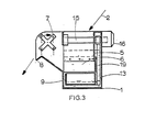
- a washing tank 1 the material to be separated, for instance scrap from a shredder, with a maximum size of the pieces of about 400 mm, from which the ferromagnetic components have already been removed, is introduced by means of a feed device 2.
- the washing tank contains a liquid separatory medium, for instance a suspension of finely-ground ferrosilicon or magnetite in water, having a specific gravity of 1.4, in which metallic components of the scrap will sink and lighter components, such as plastics, rubber, wood, etc., will float.
- a separatory compartment is partitioned off by partitions 3, 4 and 5 extending vertically into the liquid, from which compartment the floating pieces are carried to a discharge point 8 by means of a paddle wheel 7.
- the settling pieces are collected under the separatory compartment 6 in collecting trays 9 and 10.
- collection tray 9 In the extreme position shown in the drawing, collection tray 9 is about centrally on the bottom of the washing tank under separatory compartment 6; collecting tray 10 rests, tilted, on the edge of the washing tank so that the contents of this collecting tray can slide to a discharge device 11. In the other extreme position collecting tray 10 is under the separatory compartment, and collecting tray 9 rests tilted on the opposite edge of the washing tank, as shown by the dot-dash line; now collecting tray 9 empties its contents into discharge device 12.
- Collecting trays 9 and 10 are hingingly attached to arms 13 and 14, which are fixed on a horizontal shaft 15.
- This shaft 15, with the arms 13 and 14 attached to it and the trays 9 and 10, can be reciprocated between two extreme positions by a motor 16, preferably a hydraulic motor.
- a collecting plate 17 is fixed to the arms 13 and 14, on which plate settling pieces from compartment 6 are collected during the time no collecting tray is under this compartment; the pieces collected on this plate 17 then slide into the collecting tray moving to the bottom position.
- the bottom edges of the partitions 3, 4 and 5 are at such a distance over the upper edges of the trays 9 and 10 that there is no danger of pieces projecting beyond the upper edges of trays 9 and 10 getting jammed, the partitions 3, 4 and 5 have downward extensions in the form of strips of flexible material 18, 19 and 20, which may be rubber, but may also be formed by e.g., curtains of chains, and which extend to close over the edges of the trays 9 and 10.
- the upright walls of the collecting trays, or at least the back walls, should be provided with openings, to prevent the collecting trays scooping an undue quantity of separatory medium across the edge of the washing tank.
- the motor 16 has discontinuous control, in such a way that the two collecting trays 9 and 10 alternately rest for a certain time on the bottom of the washing tank in their bottom position, collecting settling particles that are to be carried off.
- This 'certain' time should of course, be so chosen, that the collecting trays get properly filled, but not overfilled; if desired, this time may be made dependent on the load of the machine.
- the motor 16 is by preference a hydraulic motor, as this can immediately produce its maximum torque when moving from standstill.
- the paddle wheel 7 is driven by a motor 21, which, if motor 16 is a hydraulic motor, preferably a hydraulic motor also.
- the specific gravity of the separatory medium is, of course, chosen in dependence on the separation to be made. As indicated above, a specific gravity of about 1.4 is in most cases suitable for separating non-metallic components from scrap. If it is desired to make a further separation of the resulting metallic fraction, for instance into a fraction mainly consisting of aluminium and aluminium alloys on. the one hand, and a heavy-metal fraction (copper, lead, etc.) on the other, a second separation apparatus of the same type may be employed, using as separatory medium, for instance, a suspension of ferrosilicon in water, with a specific gravity of 3.0.
- apparatus can also be used for separating other materials, e.g. domestic refuse, in which case paper and lightweight organic components can be separated from heavier components, such as stone, rubber, glass and metals, by means of water as separating medium, after which, if so desired, the heavier fraction can be subjected to a further separatory treatment in a second washing tank, using a medium of higher specific gravity.
- other materials e.g. domestic refuse, in which case paper and lightweight organic components can be separated from heavier components, such as stone, rubber, glass and metals, by means of water as separating medium, after which, if so desired, the heavier fraction can be subjected to a further separatory treatment in a second washing tank, using a medium of higher specific gravity.
Landscapes
- Separation Of Solids By Using Liquids Or Pneumatic Power (AREA)
Applications Claiming Priority (2)
| Application Number | Priority Date | Filing Date | Title |
|---|---|---|---|
| NL8000978 | 1980-02-16 | ||
| NL8000978A NL8000978A (nl) | 1980-02-16 | 1980-02-16 | Inrichting voor het scheiden van delen van verschillend soortelijk gewicht volgens de drijfen bezinkmethode. |
Publications (2)
| Publication Number | Publication Date |
|---|---|
| EP0045777A1 EP0045777A1 (en) | 1982-02-17 |
| EP0045777B1 true EP0045777B1 (en) | 1985-01-16 |
Family
ID=19834845
Family Applications (1)
| Application Number | Title | Priority Date | Filing Date |
|---|---|---|---|
| EP81900530A Expired EP0045777B1 (en) | 1980-02-16 | 1981-02-13 | Float-and-sink separator |
Country Status (5)
| Country | Link |
|---|---|
| US (1) | US4379048A (cg-RX-API-DMAC7.html) |
| EP (1) | EP0045777B1 (cg-RX-API-DMAC7.html) |
| JP (1) | JPH0232941B2 (cg-RX-API-DMAC7.html) |
| NL (1) | NL8000978A (cg-RX-API-DMAC7.html) |
| WO (1) | WO1981002259A1 (cg-RX-API-DMAC7.html) |
Cited By (1)
| Publication number | Priority date | Publication date | Assignee | Title |
|---|---|---|---|---|
| CN103954527A (zh) * | 2014-05-21 | 2014-07-30 | 山东大学 | 一种煤炭浮沉试验全过程自动化装置 |
Families Citing this family (8)
| Publication number | Priority date | Publication date | Assignee | Title |
|---|---|---|---|---|
| DE4209277A1 (de) * | 1992-02-11 | 1993-08-12 | Kloeckner Humboldt Deutz Ag | Vorrichtung zur sortierung von feststoffgemischen |
| US5246116A (en) * | 1992-09-22 | 1993-09-21 | Reynolds Metals Company | Method and apparatus for separation and recovery of the components from foil-containing laminates |
| JPH08168685A (ja) * | 1994-12-19 | 1996-07-02 | Toshiba Corp | 破砕・選別装置及び破砕・選別方法 |
| GB2370263B (en) * | 2000-12-21 | 2004-06-30 | Compact Power Ltd | Bag splitter and wet separator |
| DE102005017334A1 (de) * | 2005-04-14 | 2006-10-19 | Orawetz, Uta | Verfahren und Vorrichtung zur Entsorgung von Abfall |
| KR20080074900A (ko) * | 2005-10-24 | 2008-08-13 | 토마스 에이. 바레리오 | 상이한 물질들을 분류하는 공정, 시스템 및 장치 |
| CN112452524A (zh) * | 2019-09-07 | 2021-03-09 | 云南犀鸟科技有限公司 | 一种多层线路板粉碎颗粒分选装置 |
| CN115074536B (zh) * | 2022-07-06 | 2023-10-27 | 栋梁铝业有限公司 | 一种用于再生铝合金熔体的高效吸附净化设备 |
Family Cites Families (8)
| Publication number | Priority date | Publication date | Assignee | Title |
|---|---|---|---|---|
| US2752040A (en) * | 1953-08-17 | 1956-06-26 | Ore & Chemical Corp | Sink-float separatory apparatus |
| US2825460A (en) * | 1954-12-09 | 1958-03-04 | Ore & Chemical Corp | Separatory apparatus |
| US2825459A (en) * | 1954-12-09 | 1958-03-04 | Ore & Chemical Corp | Separatory apparatus |
| FR1191989A (fr) | 1957-06-19 | 1959-10-22 | Eisen & Stahlind Ag | Séparateur à gravité pour la séparation de minéraux |
| US3016144A (en) * | 1958-01-03 | 1962-01-09 | Stamicarbon | Apparatus for separating mixtures of solid particles |
| GB939128A (en) * | 1962-09-05 | 1963-10-09 | Nortons Tividale Ltd | Improvements relating to apparatus for use in the float-and-sink separation of solidmaterials into fractions |
| US3399769A (en) * | 1964-10-15 | 1968-09-03 | Gipromashugleobogashche | Dense media separator for coal dressing |
| AU6217373A (en) * | 1972-11-13 | 1975-05-08 | Luria Brothers & Co Inc | Flotation separation process |
-
1980
- 1980-02-16 NL NL8000978A patent/NL8000978A/nl unknown
-
1981
- 1981-02-13 JP JP56500739A patent/JPH0232941B2/ja not_active Expired - Lifetime
- 1981-02-13 US US06/314,082 patent/US4379048A/en not_active Expired - Fee Related
- 1981-02-13 EP EP81900530A patent/EP0045777B1/en not_active Expired
- 1981-02-13 WO PCT/NL1981/000002 patent/WO1981002259A1/en not_active Ceased
Cited By (1)
| Publication number | Priority date | Publication date | Assignee | Title |
|---|---|---|---|---|
| CN103954527A (zh) * | 2014-05-21 | 2014-07-30 | 山东大学 | 一种煤炭浮沉试验全过程自动化装置 |
Also Published As
| Publication number | Publication date |
|---|---|
| JPS57500185A (cg-RX-API-DMAC7.html) | 1982-02-04 |
| NL8000978A (nl) | 1981-09-16 |
| US4379048A (en) | 1983-04-05 |
| WO1981002259A1 (en) | 1981-08-20 |
| JPH0232941B2 (cg-RX-API-DMAC7.html) | 1990-07-24 |
| EP0045777A1 (en) | 1982-02-17 |
Similar Documents
| Publication | Publication Date | Title |
|---|---|---|
| US4940187A (en) | Systematic equipments for recycling raw materials from waste wires | |
| EP0045777B1 (en) | Float-and-sink separator | |
| US5366165A (en) | System and method for recycling of automotive oil filters | |
| US2196451A (en) | Method of and apparatus for separating, washing, and grading lump materials | |
| NL8102968A (nl) | Werkwijze en inrichting voor het terugwinnen van speciale grondstoffen uit de bij het verwerken van oude accu's als product vrijkomend afvalmateriaal. | |
| US2135957A (en) | Concentration | |
| US3834542A (en) | Magnetic separator and conveyor | |
| US2465220A (en) | Sink-float apparatus for separating solids | |
| US2753998A (en) | Method and apparatus for heavy-media separation | |
| US3615014A (en) | Method of and apparatus for solid waste recovery | |
| AU2019321077B2 (en) | A separation apparatus and method | |
| US2422203A (en) | Specific gravity separation of solids in liquid suspension | |
| US2966262A (en) | Method and apparatus for separating ores | |
| US3162296A (en) | Conveyor for magnetic material | |
| US3043430A (en) | Sand skimmer | |
| CN204211617U (zh) | 一种油污泥均质化设备 | |
| US2889043A (en) | Apparatus for separating solid materials of different specific gravities by means of a suspension | |
| US2957577A (en) | Flotation separating apparatus and method | |
| US2428777A (en) | Method and apparatus for heavymedia separation | |
| US5169005A (en) | Apparatus for separating material of lighter specific gravity from material of a heavier specific gravity | |
| US2155235A (en) | Apparatus and method for the separation of dry materials | |
| US2699870A (en) | Apparatus for separating solid particles | |
| US2734629A (en) | menzies | |
| US2701058A (en) | Apparatus for separating solid particles | |
| US2680518A (en) | Minerals separator |
Legal Events
| Date | Code | Title | Description |
|---|---|---|---|
| PUAI | Public reference made under article 153(3) epc to a published international application that has entered the european phase |
Free format text: ORIGINAL CODE: 0009012 |
|
| 17P | Request for examination filed |
Effective date: 19811002 |
|
| AK | Designated contracting states |
Designated state(s): DE GB NL |
|
| RBV | Designated contracting states (corrected) |
Designated state(s): DE GB NL |
|
| GRAA | (expected) grant |
Free format text: ORIGINAL CODE: 0009210 |
|
| AK | Designated contracting states |
Designated state(s): DE GB NL |
|
| REF | Corresponds to: |
Ref document number: 3168220 Country of ref document: DE Date of ref document: 19850228 |
|
| PLBE | No opposition filed within time limit |
Free format text: ORIGINAL CODE: 0009261 |
|
| STAA | Information on the status of an ep patent application or granted ep patent |
Free format text: STATUS: NO OPPOSITION FILED WITHIN TIME LIMIT |
|
| 26N | No opposition filed | ||
| PGFP | Annual fee paid to national office [announced via postgrant information from national office to epo] |
Ref country code: DE Payment date: 19920211 Year of fee payment: 12 |
|
| PGFP | Annual fee paid to national office [announced via postgrant information from national office to epo] |
Ref country code: GB Payment date: 19920212 Year of fee payment: 12 |
|
| PGFP | Annual fee paid to national office [announced via postgrant information from national office to epo] |
Ref country code: NL Payment date: 19920229 Year of fee payment: 12 |
|
| NLS | Nl: assignments of ep-patents |
Owner name: DSM N.V. TE HEERLEN. |
|
| PG25 | Lapsed in a contracting state [announced via postgrant information from national office to epo] |
Ref country code: GB Effective date: 19930213 |
|
| PG25 | Lapsed in a contracting state [announced via postgrant information from national office to epo] |
Ref country code: NL Effective date: 19930901 |
|
| GBPC | Gb: european patent ceased through non-payment of renewal fee |
Effective date: 19930213 |
|
| NLV4 | Nl: lapsed or anulled due to non-payment of the annual fee | ||
| PG25 | Lapsed in a contracting state [announced via postgrant information from national office to epo] |
Ref country code: DE Effective date: 19931103 |