EP0045663A2 - Spiralförmig gewickelte Membranbaueinheit für Umkehrosmose - Google Patents
Spiralförmig gewickelte Membranbaueinheit für Umkehrosmose Download PDFInfo
- Publication number
- EP0045663A2 EP0045663A2 EP81303578A EP81303578A EP0045663A2 EP 0045663 A2 EP0045663 A2 EP 0045663A2 EP 81303578 A EP81303578 A EP 81303578A EP 81303578 A EP81303578 A EP 81303578A EP 0045663 A2 EP0045663 A2 EP 0045663A2
- Authority
- EP
- European Patent Office
- Prior art keywords
- housing
- membrane
- water
- porous tube
- membrane element
- Prior art date
- Legal status (The legal status is an assumption and is not a legal conclusion. Google has not performed a legal analysis and makes no representation as to the accuracy of the status listed.)
- Withdrawn
Links
Images

Classifications
-
- B—PERFORMING OPERATIONS; TRANSPORTING
- B01—PHYSICAL OR CHEMICAL PROCESSES OR APPARATUS IN GENERAL
- B01D—SEPARATION
- B01D12/00—Displacing liquid, e.g. from wet solids or from dispersions of liquids or from solids in liquids, by means of another liquid
-
- B—PERFORMING OPERATIONS; TRANSPORTING
- B01—PHYSICAL OR CHEMICAL PROCESSES OR APPARATUS IN GENERAL
- B01D—SEPARATION
- B01D63/00—Apparatus in general for separation processes using semi-permeable membranes
- B01D63/10—Spiral-wound membrane modules
-
- B—PERFORMING OPERATIONS; TRANSPORTING
- B01—PHYSICAL OR CHEMICAL PROCESSES OR APPARATUS IN GENERAL
- B01D—SEPARATION
- B01D65/00—Accessories or auxiliary operations, in general, for separation processes or apparatus using semi-permeable membranes
- B01D65/08—Prevention of membrane fouling or of concentration polarisation
-
- B—PERFORMING OPERATIONS; TRANSPORTING
- B01—PHYSICAL OR CHEMICAL PROCESSES OR APPARATUS IN GENERAL
- B01D—SEPARATION
- B01D2313/00—Details relating to membrane modules or apparatus
- B01D2313/14—Specific spacers
- B01D2313/143—Specific spacers on the feed side
-
- B—PERFORMING OPERATIONS; TRANSPORTING
- B01—PHYSICAL OR CHEMICAL PROCESSES OR APPARATUS IN GENERAL
- B01D—SEPARATION
- B01D2321/00—Details relating to membrane cleaning, regeneration, sterilization or to the prevention of fouling
- B01D2321/20—By influencing the flow
- B01D2321/2008—By influencing the flow statically
Definitions
- This invention relates to an apparatus for removing salts and suspended solids from water, and more particularly to an apparatus, incorporating a reverse osmosis membrane, designed for installation in the main water service line of a residence, business, or industrial plant.
- Clark, U.S. Patent No. 3,716,143 designed a tubular reverse osmosis membrane assembly for household use in which the assembly is placed in series flow with the main water service line entering the home.
- the assembly requires a complex parallel-series flow scheme through eighteen different membrane cells in the assembly. Water from the main service line is diverted through three parallel flow paths, with six tubular membrane units being connected in series in each of the flow paths. Obviously, increasing the complexity and number of membrane units in the assembly increases both the cost and the chances for leaks and/or ruptures in the assembly.
- the other major type of reverse osmosis system has mainly, found' use in large commercial scale desalination units.
- Such spiral-wrapped systems employ membrane sheets spaced apart by separator grids. These systems raise the water supply pressure to several hundred pounds per square inch prior to its introduction to the reverse osmosis membrane and are principally designed for high pressure, high volume desalination of sea water. Examples of such systems include Westmoreland, U.S. Patent No.... 3,367,504: Kohl, U.S. Patent No. 3,554,378; Ishii et al, U.S. Patent No. 3,962,096; and Goldberg et al, U.S. Patent No. 3,993,566.
- a reverse osmosis membrane assembly having a spirally-wrapped reverse osmosis membrane contained therein.
- the assembly includes a housing with a feed water inlet located at a first end thereof and an untreated water outlet at the opposite end.
- a porous tube is located in the housing and defines a longitudinally extending product water flow channel, the end of the porous tube adjacent the first end of the housing being closed, and the opposite end of the tube defines a product water outlet.
- the membrane is spirally wrapped around the tube' with the interior of the membrane being in fluid communication with the interior of the tube. Spacing elements are provided for spacing adjacent layers of the membrane apart and define a multiplicity of longitudinal flow passages through the housing. The combined cross-sectional area of the fluid flow passages is at least as great as the cross-sectional area of the feed water inlet.
- the membrane is of a generally rectangular configuration and is formed by sandwiching a core of loosely packed or woven material between two sheets of membrane material. The sandwich is then sealed on three edges, leaving the fourth edge open with the packing material in fluid communication with a porous tube.
- a spacer element is provided to be placed over one surface of the membrane.
- the spacer element contains a multiplicity of ribs extending both longitudinally over the length and latitudinally over the width of the membrane.
- the spacer element is preferably fabricated from a flexible material so that it can be easily bent or rolled.
- the membrane and spacer element are spirally wrapped around the porous tube.
- the areas between the ribs of the spacer element form a multiplicity of longitudinal passages along the length of the tube for water to flow through.
- the spirally-wrapped membrane assembly is then placed in a cannister or housing having a feed water inlet and an untreated water outlet.
- the end of the porous tube facing the feed water inlet is sealed off to prevent untreated water from entering the tube.
- the opposite end of the tube defines a product water outlet passing out of the housing.
- water under pressure such as a standard household pressure of between 3.5-7 Kg/cm 2 (50-100) psia
- the flow of water is split to flow through the multiplicity of passages formed by the ribbed spacer element.
- water is forced by a reverse osmosis process through the walls of the membrane material and into the core of loosely packed material.
- the treated water in the core material follows a spiral path into the porous tube where it is then taken to storage or ultimate use.
- the spacer element is sized and arranged so that the combined cross-sectional area for flow through the flow passages formed by the spacer element is as least as great as the cross-sectional area of the feed water inlet.
- the combined cross-sectional area of the flow passages may be at least twice that of the feed water inlet. In this manner, pressure drops through the housing can be kept at less than 0.35 kg/cm 2 (5 psia), and preferably near 0 k g/ em 2 .
- the assembly embodying the present invention operates at relatively low pressures, and does not require pumps creating artificially high pressures to be operative as did some prior systems. Moreover, the membrane assembly utilizes high water flow rates to maintain the reverse osmosis membrane free from a buildup of solids and yet does not waste any water as did some prior systems. Finally, the membrane assembly utilizes a single, compact spiral-wrapped membrane element avoiding the problems of previous systems which required multiple membrane elements arranged in complex flow patterns.
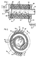
- the reverse osmosis membrane assembly 10 is designed to be positioned in the main water service line entering a home or business.
- a source of water under pressure 12 which may be a city water distribution system or a well and pump, is supplied to feed water inlet 14 of assembly 10.
- source 12 is able to supply water at pressures of from about 50-100 psia.
- Membrane assembly 10 additionally comprises a housing 16 having a spirally-wrapped reverse osmosis membrane element 18 contained therein.
- a porous tube 20 having holes 22 defines a product water collection channel along the length of housing 16.
- the end of tube 20 facing inlet 14 is sealed off to prevent any untreated water from entering the tube while the opposite end of tube 20 defines a product water outlet 24 through the opposite end of housing 16.
- Adjacent walls of the spirally wrapped membrane element 18 are spaced apart by a spacer element 34, described in further detail below, to form fluid flow passages 26 along the length of the housing. As shown, the spacer element 34 extends slightly further forward than the membrane element 18 to ensure that the leading edges of the membrane element do not obstruct fluid flow passages 26.
- water under pressure entering inlet 14 is split into a multiplicity of flow paths indicated by the arrows through passages 26. Because of the pressure differential between the water in housing 16 and the interior of tube 20, water is forced by a reverse osmosis process into the interior of membrane elements 18. From there, the treated product water, containing substantially less suspended solids and ions, follows a spiral flow path until reaching the interior of tube 20 through holes 22. From there, the product water can be sent to a storage container or used as required. Under normal operating conditions, about 14-23 liters (4-6 gallons) per day of product water will be collected.
- Dissolved salts and suspended solids which concentrate on the surfaces of membrane element 18 are flushed away by the flow of feed water through passages 26.
- Water not passing into membrane element 18 is collected at header 28 and flows out of housing 16 through untreated water outlet 30.
- the untreated water is supplied to the home and may be used in other appliances 32 such as bathtubs,, sinks, dish and clothes washers, and the like, as well as interior and exterior faucets from which treated water is not required.
- flow passages 26 are arranged so that their com- oined cross-sectional area for flow is at least as great as the cross-sectional area of the main water service line entering housing 16.
- flow passages 26 are sized so that their combined cross-sectional area for flow is at least twice that of the main service line. It has been found that obtaining sufficient area for flow of water through the membrane assembly is critical in maintaining pressure to the remainder of the household plumbing. Preferably, pressure drops are limited to less than 0.35 Kg/cm 2 (5 psia) and, even more preferably, approximately 0 Kg/cm 2 through the assembly.
- flow passages 26 are formed by a ribbed spacer element 34 which may be formed from any flexible material.
- the spacer element may be extruded or injection molded from a thermoplastic polymeric material using known techniques.
- Spacer element 34 has a plurality of ribs 36, 36' extending outwardly from a central strip 38.
- the ribs 36, 36' are substantially in line contact with adjacent walls of membrane element 18 and extend longitudinally along the length of the assembly (best shown in Fig. 4). By this arrangement, substantially all of the surface of the membrane element is available for fluid contact with the water passing through the passages 26.
- Membrane element 18 is formed by sandwiching a loosely packed core material 40 between opposing generally rectangular sheets 42, 42' of a reverse osmosis membrane material.
- Core material 40 may be a woven or nonwoven fabric or fibrous material such as a polyester.
- the membrane may be any of a number of known materials used for reverse osmosis such as regenerated cellulose or cellulose acetate.
- Three edges of the sandwich are sealed together while the fourth edge is attached and sealed to tube 20 so that core material 40 is in fluid communication with holes 22 as shown in Figs. 2 and 3.
- the membrane element 18 and spacer element 34 are then wrapped around tube 20 forming a spiral configuration.
- spacer element 34 should be sized so that it is at least flush and preferably extends somewhat beyond the ends of membrane element 18. This construction avoids any problems of fluid pressure folding over the edges of the membrane element and blocking fluid flow passages.
- the membrane assembly will be sized to complement a nominal 2.5 cm (1 inch) diameter pipe which is the main water service into a household or business.
- the assembly is approximately 30 cm (1 foot) in length and contains approximately 75 cm (2.5 lineal feet) of membrane element 18.
- the ribs on spacer element 34 are approximately 0.11 cm (0.045 inches) high and 0.08 cm (0.030 inches) wide with an edge to edge spacing of 0.11 cm (0.045 inches).
- Strip 38 is approximately 0.06 cm (0.025 inches) thick resulting in an overall spacer thickness of 75 cm (0.115 inches).
Landscapes
- Chemical & Material Sciences (AREA)
- Chemical Kinetics & Catalysis (AREA)
- Dispersion Chemistry (AREA)
- Separation Using Semi-Permeable Membranes (AREA)
Applications Claiming Priority (2)
| Application Number | Priority Date | Filing Date | Title |
|---|---|---|---|
| US17580180A | 1980-08-06 | 1980-08-06 | |
| US175801 | 1980-08-06 |
Publications (2)
| Publication Number | Publication Date |
|---|---|
| EP0045663A2 true EP0045663A2 (de) | 1982-02-10 |
| EP0045663A3 EP0045663A3 (de) | 1982-02-24 |
Family
ID=22641685
Family Applications (1)
| Application Number | Title | Priority Date | Filing Date |
|---|---|---|---|
| EP81303578A Withdrawn EP0045663A3 (de) | 1980-08-06 | 1981-08-05 | Spiralförmig gewickelte Membranbaueinheit für Umkehrosmose |
Country Status (3)
| Country | Link |
|---|---|
| EP (1) | EP0045663A3 (de) |
| KR (1) | KR830005882A (de) |
| ES (1) | ES504570A0 (de) |
Cited By (10)
| Publication number | Priority date | Publication date | Assignee | Title |
|---|---|---|---|---|
| FR2598629A1 (fr) * | 1986-05-16 | 1987-11-20 | Lopez Fernand | Module de filtration d'un liquide sous pression |
| EP0307047A1 (de) * | 1987-09-09 | 1989-03-15 | Nederlandse Organisatie Voor Toegepast-Natuurwetenschappelijk Onderzoek Tno | Membranmodul für Hyperfiltration oder Ultrafiltration von verschmutzenden Flüssigkeiten |
| EP0347174A1 (de) * | 1988-06-14 | 1989-12-20 | Desalination Systems Inc. | Spiralförmig gewickelter Membranmodul und Behandlungsverfahren |
| EP0382488A2 (de) * | 1989-02-08 | 1990-08-16 | Koch Membrane Systems, Inc | Spiralförmiger Membranmodul mit einlassseitigem Abstandshalter |
| US6881336B2 (en) | 2002-05-02 | 2005-04-19 | Filmtec Corporation | Spiral wound element with improved feed space |
| WO2005097305A1 (en) * | 2004-04-05 | 2005-10-20 | Pall Corporation | Spacer for use in filter modules |
| US20120298578A1 (en) * | 2010-02-01 | 2012-11-29 | Rodney Herrington | Systems and methods for filtration |
| CN103041708A (zh) * | 2012-12-28 | 2013-04-17 | 成都连接流体分离科技有限公司 | 一种高抗污染卷式膜元件 |
| CN111989152A (zh) * | 2018-04-26 | 2020-11-24 | 东丽株式会社 | 分离膜模块 |
| CN112610433A (zh) * | 2020-12-08 | 2021-04-06 | 南京工业大学 | 基于多孔介质的正向渗透-电动盐差能高效连续发电装置 |
Citations (7)
| Publication number | Priority date | Publication date | Assignee | Title |
|---|---|---|---|---|
| BE673853A (de) * | 1964-12-21 | 1966-04-15 | ||
| GB1094824A (en) * | 1965-04-13 | 1967-12-13 | Gen Dynamics Corp | Improvements in or relating to water purification by reverse osmosis |
| US3542203A (en) * | 1967-08-29 | 1970-11-24 | Desalination Systems | Spiral reverse osmosis device |
| FR2087928A5 (de) * | 1970-03-30 | 1971-12-31 | Aqua Chem Inc | |
| FR2101701A5 (de) * | 1970-07-15 | 1972-03-31 | Polymetrics Inc | |
| US3695446A (en) * | 1970-10-15 | 1972-10-03 | Culligan Int Co | Membrane module assembly |
| US4193872A (en) * | 1978-08-09 | 1980-03-18 | Parkinson Wayne A | Flushing system for reverse osmosis water purification units |
-
1981
- 1981-08-05 EP EP81303578A patent/EP0045663A3/de not_active Withdrawn
- 1981-08-05 ES ES504570A patent/ES504570A0/es active Granted
- 1981-08-06 KR KR1019810002862A patent/KR830005882A/ko unknown
Patent Citations (10)
| Publication number | Priority date | Publication date | Assignee | Title |
|---|---|---|---|---|
| BE673853A (de) * | 1964-12-21 | 1966-04-15 | ||
| US3367504A (en) * | 1964-12-21 | 1968-02-06 | Gulf General Atomic Inc | Spirally wrapped reverse osmosis membrane cell |
| GB1094824A (en) * | 1965-04-13 | 1967-12-13 | Gen Dynamics Corp | Improvements in or relating to water purification by reverse osmosis |
| US3542203A (en) * | 1967-08-29 | 1970-11-24 | Desalination Systems | Spiral reverse osmosis device |
| FR2087928A5 (de) * | 1970-03-30 | 1971-12-31 | Aqua Chem Inc | |
| US3716143A (en) * | 1970-03-30 | 1973-02-13 | Aqua Chem Inc | Reverse osmosis separation apparatus |
| FR2101701A5 (de) * | 1970-07-15 | 1972-03-31 | Polymetrics Inc | |
| US3679055A (en) * | 1970-07-15 | 1972-07-25 | Polymetrics Inc | Reverse osmosis water purifier |
| US3695446A (en) * | 1970-10-15 | 1972-10-03 | Culligan Int Co | Membrane module assembly |
| US4193872A (en) * | 1978-08-09 | 1980-03-18 | Parkinson Wayne A | Flushing system for reverse osmosis water purification units |
Non-Patent Citations (2)
| Title |
|---|
| Product Engineering, Vol. 49, No. 11, November 1978, pages 27-29 New York, U.S.A. "Better Membranes Further Reverse Osmosis" *page 28, column 2, figure and lines 27-36* * |
| S. SOURIRAYAN: "Reverse Osmosis", 1970, pages 475-478, Logos Press Ltd. London, G.B. *page 475, line 20 - page 476, line 6; figures 8-22; page 478, lines 6-21* * |
Cited By (14)
| Publication number | Priority date | Publication date | Assignee | Title |
|---|---|---|---|---|
| FR2598629A1 (fr) * | 1986-05-16 | 1987-11-20 | Lopez Fernand | Module de filtration d'un liquide sous pression |
| US4820413A (en) * | 1986-05-16 | 1989-04-11 | Fernand Lopez | Annular module for filtering a pressurized liquid by reverse osmosis |
| EP0307047A1 (de) * | 1987-09-09 | 1989-03-15 | Nederlandse Organisatie Voor Toegepast-Natuurwetenschappelijk Onderzoek Tno | Membranmodul für Hyperfiltration oder Ultrafiltration von verschmutzenden Flüssigkeiten |
| EP0347174A1 (de) * | 1988-06-14 | 1989-12-20 | Desalination Systems Inc. | Spiralförmig gewickelter Membranmodul und Behandlungsverfahren |
| EP0382488A2 (de) * | 1989-02-08 | 1990-08-16 | Koch Membrane Systems, Inc | Spiralförmiger Membranmodul mit einlassseitigem Abstandshalter |
| EP0382488A3 (de) * | 1989-02-08 | 1990-11-28 | Koch Membrane Systems, Inc | Spiralförmiger Membranmodul mit einlassseitigem Abstandshalter |
| US6881336B2 (en) | 2002-05-02 | 2005-04-19 | Filmtec Corporation | Spiral wound element with improved feed space |
| WO2005097305A1 (en) * | 2004-04-05 | 2005-10-20 | Pall Corporation | Spacer for use in filter modules |
| US20120298578A1 (en) * | 2010-02-01 | 2012-11-29 | Rodney Herrington | Systems and methods for filtration |
| CN103041708A (zh) * | 2012-12-28 | 2013-04-17 | 成都连接流体分离科技有限公司 | 一种高抗污染卷式膜元件 |
| CN103041708B (zh) * | 2012-12-28 | 2015-01-07 | 成都连接流体分离科技有限公司 | 一种高抗污染卷式膜元件 |
| CN111989152A (zh) * | 2018-04-26 | 2020-11-24 | 东丽株式会社 | 分离膜模块 |
| CN111989152B (zh) * | 2018-04-26 | 2022-03-15 | 东丽株式会社 | 分离膜模块 |
| CN112610433A (zh) * | 2020-12-08 | 2021-04-06 | 南京工业大学 | 基于多孔介质的正向渗透-电动盐差能高效连续发电装置 |
Also Published As
| Publication number | Publication date |
|---|---|
| ES8204976A1 (es) | 1982-05-16 |
| KR830005882A (ko) | 1983-09-14 |
| EP0045663A3 (de) | 1982-02-24 |
| ES504570A0 (es) | 1982-05-16 |
Similar Documents
| Publication | Publication Date | Title |
|---|---|---|
| US4944877A (en) | Spacerless feed channel membrane filter element | |
| US4033878A (en) | Spiral wound membrane module for direct osmosis separations | |
| US3417870A (en) | Reverse osmosis purification apparatus | |
| DE1442420C3 (de) | Vorrichtung für die umgekehrte Osmose | |
| US6190556B1 (en) | Desalination method and apparatus utilizing nanofiltration and reverse osmosis membranes | |
| US4352736A (en) | Wound flattened hollow fiber assembly having plural spaced core sections | |
| US3398834A (en) | Reverse osmosis water purification apparatus and cell therefor | |
| US3616929A (en) | Reverse osmosis module | |
| US6190557B1 (en) | Spiral wound type membrane element, running method and washing method thereof | |
| EP0045663A2 (de) | Spiralförmig gewickelte Membranbaueinheit für Umkehrosmose | |
| US3568843A (en) | Water storage system for reverse osmosis purification unit | |
| WO2003097220A1 (fr) | Dispositif et procede de separation par membrane | |
| US5234583A (en) | Semi-permeable membrane filtering systems for swimming pools | |
| JP3098600B2 (ja) | スパイラル型分離膜モジュール | |
| JPH09141063A (ja) | 中空糸膜モジュール | |
| TWI239262B (en) | Spiral membrane element, reverse osmosis membrane module, and reverse osmosis membrane apparatus | |
| EP1464377A1 (de) | Spiralförmig gewickeltes Membranelement | |
| US6251271B1 (en) | Device for purifying a fluid | |
| JPS5935642B2 (ja) | 液体分離素子 | |
| EP3371109A1 (de) | Verfahren und systeme zur behandlung von abwasser mittels vorwärtsosmose | |
| CN108697973A (zh) | 多叶膜组件及其制造方法 | |
| JPH10230145A (ja) | スパイラル型膜エレメント | |
| CN109999673B (zh) | 一种卷式膜元件 | |
| CN115385419B (zh) | 一种多重滤腔的反渗透膜装置 | |
| RU2199377C1 (ru) | Мембранная установка для разделения растворов |
Legal Events
| Date | Code | Title | Description |
|---|---|---|---|
| PUAI | Public reference made under article 153(3) epc to a published international application that has entered the european phase |
Free format text: ORIGINAL CODE: 0009012 |
|
| PUAL | Search report despatched |
Free format text: ORIGINAL CODE: 0009013 |
|
| AK | Designated contracting states |
Designated state(s): AT BE CH DE FR GB IT LU NL SE |
|
| AK | Designated contracting states |
Designated state(s): AT BE CH DE FR GB IT LU NL SE |
|
| STAA | Information on the status of an ep patent application or granted ep patent |
Free format text: STATUS: THE APPLICATION IS DEEMED TO BE WITHDRAWN |
|
| 18D | Application deemed to be withdrawn |
Effective date: 19830207 |
|
| RIN1 | Information on inventor provided before grant (corrected) |
Inventor name: DAVIS, STEPHEN H. |