EP0045615A1 - Vehicle or building ventilating system driven by moving air - Google Patents
Vehicle or building ventilating system driven by moving air Download PDFInfo
- Publication number
- EP0045615A1 EP0045615A1 EP81303448A EP81303448A EP0045615A1 EP 0045615 A1 EP0045615 A1 EP 0045615A1 EP 81303448 A EP81303448 A EP 81303448A EP 81303448 A EP81303448 A EP 81303448A EP 0045615 A1 EP0045615 A1 EP 0045615A1
- Authority
- EP
- European Patent Office
- Prior art keywords
- rotor
- fan
- air
- vehicle
- rotor blades
- Prior art date
- Legal status (The legal status is an assumption and is not a legal conclusion. Google has not performed a legal analysis and makes no representation as to the accuracy of the status listed.)
- Granted
Links
Images

Classifications
-
- F—MECHANICAL ENGINEERING; LIGHTING; HEATING; WEAPONS; BLASTING
- F04—POSITIVE - DISPLACEMENT MACHINES FOR LIQUIDS; PUMPS FOR LIQUIDS OR ELASTIC FLUIDS
- F04D—NON-POSITIVE-DISPLACEMENT PUMPS
- F04D25/00—Pumping installations or systems
- F04D25/02—Units comprising pumps and their driving means
- F04D25/04—Units comprising pumps and their driving means the pump being fluid-driven
- F04D25/045—Units comprising pumps and their driving means the pump being fluid-driven the pump wheel carrying the fluid driving means, e.g. turbine blades
-
- B—PERFORMING OPERATIONS; TRANSPORTING
- B60—VEHICLES IN GENERAL
- B60H—ARRANGEMENTS OF HEATING, COOLING, VENTILATING OR OTHER AIR-TREATING DEVICES SPECIALLY ADAPTED FOR PASSENGER OR GOODS SPACES OF VEHICLES
- B60H1/00—Heating, cooling or ventilating devices
- B60H1/00457—Ventilation unit, e.g. combined with a radiator
- B60H1/00471—The ventilator being of the radial type, i.e. with radial expulsion of the air
-
- B—PERFORMING OPERATIONS; TRANSPORTING
- B63—SHIPS OR OTHER WATERBORNE VESSELS; RELATED EQUIPMENT
- B63J—AUXILIARIES ON VESSELS
- B63J2/00—Arrangements of ventilation, heating, cooling, or air-conditioning
- B63J2/02—Ventilation; Air-conditioning
-
- F—MECHANICAL ENGINEERING; LIGHTING; HEATING; WEAPONS; BLASTING
- F24—HEATING; RANGES; VENTILATING
- F24F—AIR-CONDITIONING; AIR-HUMIDIFICATION; VENTILATION; USE OF AIR CURRENTS FOR SCREENING
- F24F7/00—Ventilation
- F24F7/02—Roof ventilation
- F24F7/025—Roof ventilation with forced air circulation by means of a built-in ventilator
Definitions
- the ventilator can be used in road or rail vehicles, on boats and ships, or on buildings or caravans, including stationary caravans. If increased power is required the height of the rotor should be increased.
- the mounting is between the rotor and the fan with the fan being inside the vehicle. In this form the device causes air circulation wholly within the vehicle.
Landscapes
- Engineering & Computer Science (AREA)
- Mechanical Engineering (AREA)
- Chemical & Material Sciences (AREA)
- Combustion & Propulsion (AREA)
- General Engineering & Computer Science (AREA)
- Ocean & Marine Engineering (AREA)
- Physics & Mathematics (AREA)
- Thermal Sciences (AREA)
- Structures Of Non-Positive Displacement Pumps (AREA)
- Ventilation (AREA)
- Air-Conditioning For Vehicles (AREA)
Abstract
Description
- This invention relates to an improved ventilating or air moving device, suitable for use for example on vehicles (including ships) or for ventilating buildings.
- British Patent No. 295,019 describes a vehicle ventilating device having a driving rotor mounted between two parallel discs on top of the vehicle and coupled to drive a centrifugal fan, which draws air axially up through an aperture in the vehicle roof and drives it out through a circular gap between the bottom of the rotor and the roof. The rotor is driven by air flow as the vehicle moves, or by the wind, and is effective to operate the fan.
- In an alternative arrangement the fan outlet is arranged to be within the vehicle so that air is circulated wholly within the vehicle. In this way air can be circulated to a refrigerating system in a refrigerated van, for example.
- The prior devices have all been costly and have tended to be rather high, adding to the overall height of the vehicle. This is clearly disadvantageous.
- Furthermore, since the rotor is mounted between two discs the upper disc must generally be supported by peripheral struts and thus the device when mounted on a vehicle tends to catch on overhanging trees and the like and is very liable to damage both to itself and to the roof of the vehicle on which it is mounted.
- This invention provides a ventilating device comprising a centrifugal fan and a rotor capable of being rotated by moving air for driving the fan, the rotor comprising a base plate for outwardly deflecting air passing through the fan and an air scoop extending upwardly from the base plate comprising two arcuate rotor blades in spaced overlapping relation with their concave surfaces in opposition to define a sinusoidal passage between the rotor blades, and a cover plate extending only over the area defined between the rotor blades.
- The rotor and fan are carried on a mounting by which the ventilating device can be mounted on a vehicle or on a building. The mounting also preferably carries the bearings for the fan/rotor, the bearings preferably forming a sealed unit.
- The ventilating device of the invention may be manufactured almost entirely of plastics material, for example polyproplyene, ABS or the like but the mounting may be made in plastics or metal, for example zinc alloy or aluminium.
- The ventilating device of the invention may be considerably lighter than hitherto known devices of similar capacity and operate sufficiently at much lower air speeds. A vehicle fitted with the device is much less vulnerable to damage from overhanging trees since because the cover plate does not extend beyond the rotor blades there is much less tendency for the upstanding part of the device to become caught up.
- The ventilating device of the invention may also comprise a closable shutter unit mounted below the centrifugal fan to control tle amount of air drawn into the fan.
- The invention will now be described in greater detail by way of example with reference to the drawings, in which:-
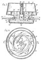
- Fig. 1 is a perspective view of an improved ventilator embodying the invention;
- Fig. 2 is a plan view of the rotor;
- Fig. 3 is a sectional elevational view through the ventilator when mounted on a roof with a shutter arranged below the ventilator input; and
- Fig. 4 is an underplan view of the ventilator taken on the line IV-IV on Fig. 3.
- Referring to the drawings, the ventilator comprises a rotor moulding or
air scoop 10 which is shaped to be driven in rotation by air flow as indicated by the chain-dotted lines in Fig. 2. We have found that in fact the rotor need not be mounted between two discs, as had hitherto been thought, but that good results are achieved with the construction illustrated in which only the area defined between the tworotor blades 12 is covered as at 14. This has constructional and operational advantages in that it is possible to mould the rotor in a single moulding, and that it is less likely to catch on obstructions, such as the branches of trees, due to its relatively smooth contour. - The bottom edges of the rotor fit into
slots 16, seen in Fig.4, which thus shows clearly the shape of theblades 12. Instead of slots, embossed recesses may be used. The slots orrecesses 16 are formed in acover plate 20 which has adownturned rim 22 and carries on its lower surface centrifugalfan impeller blades 24, seen in Figs. 3 and 4. Thelower edges 26 of theblades 24 are received inslots 28 in a lower cover plate orshield 30, theplates blades 24 are securely attached to thecover plate 30, pegs orpins 29 are used to stake the lower edges of the blades and are sealed over with the application of heat. - All the structure so far described is mounted for rotation on the
vehicle roof 32 by means of a spokedmounting ring 34 having a centralhollow boss 36. Thecover plate 30 fits as closely as possible around the edge of themounting ring 34. Theboss 36 contains two sealed roller bearing units one of which is shown at 38 and which allows rotation of acentral shaft 40 axially held in the bearings. Therotor 10 has a correspondingcentral boss 42 which receives thisshaft 40 and is counterbored at 44 to receive twonuts 46 which are threaded onto the end of theshaft 40 to secure therotor 10 andcover plate 20. A small cover disc 48 fits into the top of therecess 44. - In use the air is driven outwardly by the
centrifugal fan blades 24 driven byrotor 10 and air is drawn upwardly through anaperture 50 in thevehicle roof 32 as a result. The rotor operation is surprisingly effective and in one example started to be operative at an air speed of about 5 mph (about 8 Km/hr) and was fully effective at an air speed of about 10 mph (about 16 Km/hr) over the vehicle roof and was fully effective at an air speed of about..20 mph (about 32 Km/hrl. - Beneath the
vehicle roof 32 it is possible to provide aclosable shutter unit 52. This is essentially in two parts, namely a circular mounting androof support plate 54 and ashutter 56 which clips to the rim of the mounting plate by three sprung lugs spaced around the periphery. Themounting plate 54 has mounting holes which are aligned with holes in themounting plate 34 so thatbolts 58 can secure both the ventilator and shutter unit to thevehicle roof 32. This strengthens the roof around theaperture 50. A neoprene seal or gasket can be included in the assembly. Theshutter 56 itself comprises two slotted grilles one of which is slidable over the other by means of abutton 60. The shutter may be flat as shown or slightly curved (dished). - It is seen that the ventilator consists essentially of the
rotor 10, cover andfan plate 20, andlower shield plate 30, all of which can be formed from polypropylene mouldings. Themounting ring 34 can be a zinc alloy casting. The shutter unit can likewise be formed of plastics mouldings, using for instance a polypropylene co-polymer or ABS plastic. - It will be appreciated that the ventilator can be used in road or rail vehicles, on boats and ships, or on buildings or caravans, including stationary caravans. If increased power is required the height of the rotor should be increased. In a modified device, the mounting is between the rotor and the fan with the fan being inside the vehicle. In this form the device causes air circulation wholly within the vehicle.
Claims (5)
Priority Applications (1)
| Application Number | Priority Date | Filing Date | Title |
|---|---|---|---|
| AT81303448T ATE13336T1 (en) | 1980-07-25 | 1981-07-27 | MOVING AIR VENTILATION SYSTEM FOR VEHICLES OR BUILDINGS. |
Applications Claiming Priority (2)
| Application Number | Priority Date | Filing Date | Title |
|---|---|---|---|
| GB8024429 | 1980-07-25 | ||
| GB8024429 | 1980-07-25 |
Publications (2)
| Publication Number | Publication Date |
|---|---|
| EP0045615A1 true EP0045615A1 (en) | 1982-02-10 |
| EP0045615B1 EP0045615B1 (en) | 1985-05-15 |
Family
ID=10515038
Family Applications (1)
| Application Number | Title | Priority Date | Filing Date |
|---|---|---|---|
| EP81303448A Expired EP0045615B1 (en) | 1980-07-25 | 1981-07-27 | Vehicle or building ventilating system driven by moving air |
Country Status (4)
| Country | Link |
|---|---|
| EP (1) | EP0045615B1 (en) |
| AT (1) | ATE13336T1 (en) |
| DE (1) | DE3170498D1 (en) |
| IE (1) | IE51431B1 (en) |
Cited By (3)
| Publication number | Priority date | Publication date | Assignee | Title |
|---|---|---|---|---|
| GB2293414A (en) * | 1994-09-22 | 1996-03-27 | Lai Yu Ming | Wind-driven ventilating fan |
| CN114963328A (en) * | 2021-02-19 | 2022-08-30 | 青岛海尔空调器有限总公司 | Wall-mounted air conditioner indoor unit |
| GB2620192A (en) * | 2022-07-01 | 2024-01-03 | Flettner Ventilator Ltd | Ventilation device |
Families Citing this family (1)
| Publication number | Priority date | Publication date | Assignee | Title |
|---|---|---|---|---|
| WO2021010862A1 (en) * | 2019-07-17 | 2021-01-21 | ИВАНОВ, Дмитрий Станиславич | Rotary roof vent |
Citations (3)
| Publication number | Priority date | Publication date | Assignee | Title |
|---|---|---|---|---|
| DE175820C (en) * | ||||
| DE521795C (en) * | 1931-03-26 | Anton Flettner | Fan with centrifuge or the like, especially for vehicles | |
| GB1523406A (en) * | 1977-07-29 | 1978-08-31 | Marquez A | Ventilator |
Family Cites Families (2)
| Publication number | Priority date | Publication date | Assignee | Title |
|---|---|---|---|---|
| GB295019A (en) * | 1927-08-05 | 1929-10-16 | Anton Flettner | Ventilating device for vehicles |
| GB1518151A (en) * | 1976-05-14 | 1978-07-19 | Peck A | Energy extracting machine |
-
1981
- 1981-07-27 AT AT81303448T patent/ATE13336T1/en active
- 1981-07-27 EP EP81303448A patent/EP0045615B1/en not_active Expired
- 1981-07-27 IE IE1700/81A patent/IE51431B1/en not_active IP Right Cessation
- 1981-07-27 DE DE8181303448T patent/DE3170498D1/en not_active Expired
Patent Citations (3)
| Publication number | Priority date | Publication date | Assignee | Title |
|---|---|---|---|---|
| DE175820C (en) * | ||||
| DE521795C (en) * | 1931-03-26 | Anton Flettner | Fan with centrifuge or the like, especially for vehicles | |
| GB1523406A (en) * | 1977-07-29 | 1978-08-31 | Marquez A | Ventilator |
Cited By (6)
| Publication number | Priority date | Publication date | Assignee | Title |
|---|---|---|---|---|
| GB2293414A (en) * | 1994-09-22 | 1996-03-27 | Lai Yu Ming | Wind-driven ventilating fan |
| CN114963328A (en) * | 2021-02-19 | 2022-08-30 | 青岛海尔空调器有限总公司 | Wall-mounted air conditioner indoor unit |
| CN114963328B (en) * | 2021-02-19 | 2023-05-16 | 青岛海尔空调器有限总公司 | Wall-mounted air conditioner indoor unit |
| GB2620192A (en) * | 2022-07-01 | 2024-01-03 | Flettner Ventilator Ltd | Ventilation device |
| WO2024003796A1 (en) | 2022-07-01 | 2024-01-04 | Flettner Ventilator Limited | Ventilation device |
| GB2620192B (en) * | 2022-07-01 | 2024-06-19 | Flettner Ventilator Ltd | Rotor driven ventilator with surface modifications |
Also Published As
| Publication number | Publication date |
|---|---|
| IE51431B1 (en) | 1986-12-24 |
| EP0045615B1 (en) | 1985-05-15 |
| DE3170498D1 (en) | 1985-06-20 |
| IE811700L (en) | 1982-01-25 |
| ATE13336T1 (en) | 1985-06-15 |
Similar Documents
| Publication | Publication Date | Title |
|---|---|---|
| KR101040844B1 (en) | Cooling channel for HBAC blower assembly in automobile | |
| US6155650A (en) | Anti-dust and cooling cover for brake assembly | |
| US4269563A (en) | Wind turbine | |
| US3479947A (en) | Ventilator unit | |
| NL194155C (en) | Air purifier. | |
| US3290021A (en) | Portable humidifier | |
| US5772572A (en) | Laboratory centrifuge having a casing cover and rotor chamber adapted to exhaust circulated air | |
| US3879742A (en) | Weather-proof enclosure for video camera or the like having centrifugal action window cleaner | |
| US4171937A (en) | Grill panel and motor mount assembly | |
| SE443408B (en) | RADIAL SPLIT FOR HEATING OR AIR CONDITIONING INSTALLATIONS IN VEHICLES | |
| FR2548311A1 (en) | COOLING SYSTEM FOR DISC BRAKES, ESPECIALLY MOTOR VEHICLES | |
| US10300739B1 (en) | Wheel mounted cooling fan | |
| EP0045615A1 (en) | Vehicle or building ventilating system driven by moving air | |
| GB2081882A (en) | Ventilator | |
| US4905461A (en) | Mower sheave fan and drive cover port arrangement | |
| US4013146A (en) | Disc brake cooling structure | |
| US3942863A (en) | Arrangement for a rotating automobile mirror | |
| EP0366414B1 (en) | Air cooler pump means | |
| US2766573A (en) | Mower with air-cooled electric motor and cutting disc | |
| JPH09508794A (en) | Rotary core wiper device for plant treatment | |
| US4181312A (en) | Slinger device | |
| TR199800733A2 (en) | Vantilat�r d�zeni. | |
| US4204388A (en) | Air cushion mowers | |
| US2896424A (en) | Condensate disposal arrangement for air conditioner | |
| JP3018937U (en) | Drainage fins for foil |
Legal Events
| Date | Code | Title | Description |
|---|---|---|---|
| PUAI | Public reference made under article 153(3) epc to a published international application that has entered the european phase |
Free format text: ORIGINAL CODE: 0009012 |
|
| AK | Designated contracting states |
Designated state(s): AT BE CH DE FR IT LU NL SE |
|
| 17P | Request for examination filed |
Effective date: 19820809 |
|
| ITF | It: translation for a ep patent filed | ||
| GRAA | (expected) grant |
Free format text: ORIGINAL CODE: 0009210 |
|
| AK | Designated contracting states |
Designated state(s): AT BE CH DE FR IT LI LU NL SE |
|
| PG25 | Lapsed in a contracting state [announced via postgrant information from national office to epo] |
Ref country code: NL Effective date: 19850515 Ref country code: LI Effective date: 19850515 Ref country code: CH Effective date: 19850515 Ref country code: BE Effective date: 19850515 Ref country code: AT Effective date: 19850515 |
|
| REF | Corresponds to: |
Ref document number: 13336 Country of ref document: AT Date of ref document: 19850615 Kind code of ref document: T |
|
| PG25 | Lapsed in a contracting state [announced via postgrant information from national office to epo] |
Ref country code: SE Effective date: 19850530 |
|
| REF | Corresponds to: |
Ref document number: 3170498 Country of ref document: DE Date of ref document: 19850620 |
|
| ET | Fr: translation filed | ||
| PG25 | Lapsed in a contracting state [announced via postgrant information from national office to epo] |
Ref country code: LU Free format text: LAPSE BECAUSE OF NON-PAYMENT OF DUE FEES Effective date: 19850731 |
|
| REG | Reference to a national code |
Ref country code: CH Ref legal event code: PL |
|
| NLV1 | Nl: lapsed or annulled due to failure to fulfill the requirements of art. 29p and 29m of the patents act | ||
| PLBE | No opposition filed within time limit |
Free format text: ORIGINAL CODE: 0009261 |
|
| STAA | Information on the status of an ep patent application or granted ep patent |
Free format text: STATUS: NO OPPOSITION FILED WITHIN TIME LIMIT |
|
| 26N | No opposition filed | ||
| ITTA | It: last paid annual fee | ||
| PGFP | Annual fee paid to national office [announced via postgrant information from national office to epo] |
Ref country code: FR Payment date: 20000711 Year of fee payment: 20 |
|
| PGFP | Annual fee paid to national office [announced via postgrant information from national office to epo] |
Ref country code: DE Payment date: 20000724 Year of fee payment: 20 |