EP0044731A2 - Wägevorrichtung und -verfahren für ein Förderband - Google Patents
Wägevorrichtung und -verfahren für ein Förderband Download PDFInfo
- Publication number
- EP0044731A2 EP0044731A2 EP81303299A EP81303299A EP0044731A2 EP 0044731 A2 EP0044731 A2 EP 0044731A2 EP 81303299 A EP81303299 A EP 81303299A EP 81303299 A EP81303299 A EP 81303299A EP 0044731 A2 EP0044731 A2 EP 0044731A2
- Authority
- EP
- European Patent Office
- Prior art keywords
- article
- weigh
- weighed
- conveyor
- weigh head
- Prior art date
- Legal status (The legal status is an assumption and is not a legal conclusion. Google has not performed a legal analysis and makes no representation as to the accuracy of the status listed.)
- Ceased
Links
- 238000005303 weighing Methods 0.000 title claims abstract description 28
- 238000000034 method Methods 0.000 title claims abstract description 22
- 238000011144 upstream manufacturing Methods 0.000 claims abstract description 40
- 230000009471 action Effects 0.000 claims abstract description 16
- 238000013213 extrapolation Methods 0.000 claims abstract description 4
- 238000006073 displacement reaction Methods 0.000 claims description 7
- 230000008859 change Effects 0.000 claims description 5
- 235000015895 biscuits Nutrition 0.000 description 25
- 238000012545 processing Methods 0.000 description 4
- 238000012546 transfer Methods 0.000 description 4
- 230000000712 assembly Effects 0.000 description 3
- 238000000429 assembly Methods 0.000 description 3
- 238000004519 manufacturing process Methods 0.000 description 3
- 238000004806 packaging method and process Methods 0.000 description 3
- 238000003860 storage Methods 0.000 description 2
- 230000000007 visual effect Effects 0.000 description 2
- 238000012935 Averaging Methods 0.000 description 1
- 238000010276 construction Methods 0.000 description 1
- 238000009826 distribution Methods 0.000 description 1
- 238000012423 maintenance Methods 0.000 description 1
- 238000005259 measurement Methods 0.000 description 1
- 238000012856 packing Methods 0.000 description 1
- 230000008569 process Effects 0.000 description 1
- 230000004044 response Effects 0.000 description 1
- 230000032258 transport Effects 0.000 description 1
Images


Classifications
-
- G—PHYSICS
- G01—MEASURING; TESTING
- G01G—WEIGHING
- G01G19/00—Weighing apparatus or methods adapted for special purposes not provided for in the preceding groups
Definitions
- This invention relates to a conveyor weighing assembly and associated method for weighing individually articles which are being transported by a conveyor and which need to be weighed whilst they are being transported on the conveyor from, say, a production line to a packaging station.
- Known forms of in-line conveyor weighing devices and assemblies comprise a weigh head and associated apparatus for transferring an article to be weighed from the conveyor or from an upstream portion thereof on to the weigh head and/or from the weigh head back to the conveyor or on to a downstream conveyor portion.
- a major disadvantage of these known forms of conveyor weighing assembly resides in the substantial amount of associated apparatus which is required to transfer the article to be weighed to the weigh head and, subsequently, the weighed article from the weigh head.
- An object of the present invention is to provide a weighing assembly which can be incorporated into a conveyor system and which eliminates the disadvantages associated with known devices of this type.
- an assembly for weighing individually articles being transported by a conveyor comprising an upstream conveyor portion, a downstream conveyor portion and a weigh head which is arranged to receive from the upstream conveyor portion an article to be weighed, which is arranged to weigh the article when it has been received from the upstream conveyor portion, whilst the article is stationary on the weigh head, and-which allows the weighed article to be moved on to the downstream conveyor portion as a consequence of the action on the weighed stationary article of the following article being received on the weigh head from the upstream conveyor portion.
- a method of weighing an article being transported by a conveyor comprises causing the article to move from an upstream portion of the conveyor on to a weigh head by the action of the upstream conveyor portion on the article, weighing the article whilst it is stationary on the weigh head, and causing the weighed stationary article to be moved on to a downstream portion of the conveyor, as a consequence of the action on the weighed article of the following article as it is received on the weigh head from the upstream portion of the conveyor.
- the weigh head, and any associated weighing apparatus and/or electronic circuitry, is physically separated from the two conveyor portions.
- the article to be weighed can be moved on to the weigh head by the momentum acquired by its movement along the upstream conveyor portion, as it leaves the end thereof, by the pushing action of the following article on the upstream conveyor portion, by the pushing action of the upstream conveyor portion, or by any combination thereof.
- the downstream conveyor portion is at a lower level than that of the upstream conveyor portion, with the weigh head located at an intermediate level between the two conveyor portions.
- the movement of the weighed article from the weigh head may be assisted by the engagement of the leading end of the article with the downstream conveyor portion, whereby the weighed article is finally dragged or drawn from the weigh head by the movement of the downstream conveyor portion.
- the impact of the following article as it moves from the upstream conveyor portion on to the weigh head is sufficient to propel the weighed article from the weigh head to the downstream conveyor portion, without any assistance from the latter by the previously-described dragging or-drawing action.
- the weigh head is associated with a weigh cell which is connected to a microprocessor for providing a signal and/or indication of the weight of the article upon the weigh head. Successive weight signals can then be used to provide a continuous read-out of the individual and/or average weight of the articles which have been weighed.
- the microprocessor is programmed to scan a signal representative of the vertical movement of or loading upon the weigh head during each weighing operation, and to determine that portion of the signal having the smallest gradient on a displacement or loading versus time basis.
- the microprocessor can be programmed to predict such a minimum gradient by extrapolation. The minimum gradient portion of the signal provides the most accurate weight reading.
- the microprocessor can be programmed to sense from the signal the presence of the following article, without the need for any sensing means, such as a photocell or microswitch, associated with the weigh head.
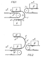
- a conveyor weighing assembly comprises a weigh head 1 having an upper cradle portion 2, an intermediate arcuate portion 3 and a lower portion 4 connected, via a vertically movable member 5, to a weigh cell 6.
- the arcuate portion 3 of the weigh head is located between an upstream conveyor portion 7 and a downstream conveyor portion 8 of a main conveyor for transporting spaced packets of biscuits 9, in the direction of the arrows A, from a production line (not shown) to a packaging, station (not shown), where the biscuit packets are boxed for subsequent storage and/or distribution.
- the weigh cell 6 is connected to a microprocessor 10 which has a read-out facility 12.
- the upstream conveyor portion 7 is at a higher level than the downstream conveyor portion 8, whilst the cradle portion 2 of the weigh head is located at an intermediate level therebetween.
- a biscuit packet 9 is weighed in a stationary position upon the cradle portion 2 of the weigh head 1.
- the weight of the packet 9 is sensed by the weigh cell 6 which then feeds an appropriate signal to the microprocessor 10 which converts the signal into a corresponding packet weight signal for storage and/or further processing. Whilst this weighing operation is being carried out, the following biscuit packet 9' is being transported by the upstream conveyor portion 7 towards the weigh head 1. As the leading end of the packet 9' leaves the conveyor portion 7, the packet 9' tilts downwardly, whereby the lower edge of its leading end drops on to the upstream end of the cradle portion 2.
- the packet 9' is still in engagement with the conveyor portion 7, such that the packet 9' is pushed on to the cradle portion 2 and its leading end engages with the trailing end of the weighed packet 9.
- the further pushing action of the upstream conveyor portion 7 upon the packet 9' causes the latter to push the weighed packet 9 off the leading end of the cradle portion 2, such that the lower edge of the leading end of the packet 9 drops on to the downstream conveyor portion 8.
- the conveyor portion 8 then drags or draws the weighed packet 9 from the cradle portion 2 of the weigh head, whilst the following packet 9' now becomes located in a stationary.position upon the cradle portion 2, at which point its weight is sensed by the weigh cell 6.
- This weighing operation is repeated for successive packets of biscuits following the packet 9'.
- the output signal representative of the weight of each weighed packet may be fed from the microprocessor 10 to the read-out facility 12 to provide an immediate visual indication of the weight of each packet and/or may undergo further processing to provide a continuous read-out of such parameters as the precentage variation in the weight of each package, a continuous averaging of the packet weights, and/or a standard deviation reading.
- a weigh head I' is suspended from a weigh cell 6' and has a lower cradle portion 2', an intermediate portion 3' and an upper portion 4'.
- This latter portion 4' is connected to the weigh cell 6' and the intermediate portion 3' is located between the upstream conveyor portion 7' and downstream conveyor portion 8' of the main conveyor transporting packets of biscuits 9, in the direction of the arrows A.
- the operation of the weigh head 1' and its associated weigh cell 6' and microprocessor 10' is identical to that of the corresponding components described with reference to Figs. 1 and 3, except that, in this case, the weigh head 1' is suspended from above by the weigh cell 6'.
- Fig. 6 there is shown a portion of a curve of a graph read-out of the output signal from either weigh cell 6, 6' representing the vertical movement of the weigh head with respect to time.
- the minimum, substantially horizontal portion M of each period of the curve represents the majority of the time during which a packet is stationary upon the weigh head 1, 1' during the actual weighing operation.
- the point N or the curve is the instant at which the lower edge of the leading end of the following packet 9' drops on to the cradle portion 2, 2' of the weigh head 1, 1'.
- the subsidiary peak portion P on the curve is the point at which the leading end of the following packet 9' engages the trailing end of the weighed packet 9.
- the other subsidiary peak portion Q on the curve is the instant at which the lower edge of the leading end of the weighed packet 9 just engages with the downstream conveyor portion 8, 8' and the maximum point R of the curve represents the weighed packet 9 dropping from the cradle portion 2, 2' of the weigh head 1, 1', such that it is completely supported by the downstream conveyor portion 8, 8', whilst the following packet 9' is now located in a stationary position on the cradle portion.
- the steeply negative dradient portion of the curve, between the point R and the portion M, represents the response time associated with the downward movement of the weigh head 1, 1'.
- the microprocessor 10, 10' is programmed to scan continuously the output signal, represented by the curve shown in Fig. 6, to determine the minimum numerical gradient which occurs along the portion M of the curve. In this way, an extremely accurate measurement of the weight of the packet 9 upon the weigh head is obtained, although the output signal from the microprocessor 10, 10' and, as a consequence, any visual read-out at facility 12, 12', lags the - weighing process by one article.
- microprocessor 10, 10' can be programmed to predict the minimum gradient along the curve portion M by extrapolation.
- a feedback signal from the microprocessor 10, lO' to a filling or other processing station upstream of the weigh head 1, 1' can be used to vary the contents of the individual biscuits or the packets of biscuits, in dependence upon one or more of the variation parameters of the weighed packets being outside a predetermined pair of upper and lower weight limits.
- the microprocessor 10, 10' may be programmed to sense the presence of the next article to be weighed upon the weigh head 1, 1' by detecting, say, a sudden change of gradient in the signal curve.
- the programmed microprocessor could detect the change of polarity in the gradient of the curve on either side of the point R, as shown in Fig.6, and the subsequent change of gradient polarity at the succeeding point R, whereby the microprocessor scans that portion of the curve between the points R and R' to determine the minimum gradient on the curve portion M.
- a feedback signal from the microprocessor 10, 10' to a filling or other processing station upstream of the weigh head 1, 1' can be used to vary the contents of the individual biscuits or the packets of biscuits, in dependence upon one or more of the variation parameters of the weighed packets being outside a predetermined pair or upper and lower weight limits.
- Each transverse row of biscuits 69 is moved on to the platform 62 by the action of the oven band 67.
- the weighing operation is then carried out by the weigh head 63 and the following row of biscuits 69 then transfers the weighed biscuits on to the output conveyor 68 by a pushing action.
- a weigh platform 62 for each biscuits of a row of biscuits may be provided, whereby various parameters for the biscuits can be determined, as discussed above.
- a single platform 62 for each row of biscuits 69 may be used, in which case the measured weight corresponds to the or each row.
- the associated electronic circuitry, such as the weigh cell, microprocessor and read-out may be identical or very similar to that used with the assemblies described above with reference to Figs. 1 to 4.
- the method of determining the most accurate weight of each biscuit or each biscuit row may be that described above with reference to Fig. 6, that is, using the minimum gradient on the displacement time curve.
- a strain gauge arrangement could be used, whereby the curve representative of the output signal therefrom would be a loading/time curve, rather than the displacement/time curve associated with the movable weigh heads 1, 1' described above.
Landscapes
- Physics & Mathematics (AREA)
- General Physics & Mathematics (AREA)
- Sorting Of Articles (AREA)
Applications Claiming Priority (2)
| Application Number | Priority Date | Filing Date | Title |
|---|---|---|---|
| GB8023652 | 1980-07-18 | ||
| GB8023652 | 1980-07-18 |
Publications (2)
| Publication Number | Publication Date |
|---|---|
| EP0044731A2 true EP0044731A2 (de) | 1982-01-27 |
| EP0044731A3 EP0044731A3 (de) | 1983-02-23 |
Family
ID=10514893
Family Applications (1)
| Application Number | Title | Priority Date | Filing Date |
|---|---|---|---|
| EP81303299A Ceased EP0044731A3 (de) | 1980-07-18 | 1981-07-17 | Wägevorrichtung und -verfahren für ein Förderband |
Country Status (2)
| Country | Link |
|---|---|
| EP (1) | EP0044731A3 (de) |
| AU (1) | AU553301B2 (de) |
Cited By (1)
| Publication number | Priority date | Publication date | Assignee | Title |
|---|---|---|---|---|
| GB2214646A (en) * | 1988-01-13 | 1989-09-06 | Post Office | High speed weighing apparatus |
Family Cites Families (3)
| Publication number | Priority date | Publication date | Assignee | Title |
|---|---|---|---|---|
| CH595783A5 (en) * | 1976-05-03 | 1978-02-28 | Burrus & Cie | Cigarette testing machine using electronic balance |
| GB1549785A (en) * | 1977-01-07 | 1979-08-08 | Nat Res Dev | Conveying apparatus |
| GB2009940B (en) * | 1977-12-10 | 1982-04-28 | Avery Ltd W & T | Position sensing transducer |
-
1981
- 1981-07-16 AU AU73035/81A patent/AU553301B2/en not_active Ceased
- 1981-07-17 EP EP81303299A patent/EP0044731A3/de not_active Ceased
Cited By (3)
| Publication number | Priority date | Publication date | Assignee | Title |
|---|---|---|---|---|
| GB2214646A (en) * | 1988-01-13 | 1989-09-06 | Post Office | High speed weighing apparatus |
| US4967857A (en) * | 1988-01-13 | 1990-11-06 | The Post Office | Weighing apparatus |
| GB2214646B (en) * | 1988-01-13 | 1991-10-02 | Post Office | Weighing apparatus |
Also Published As
| Publication number | Publication date |
|---|---|
| AU7303581A (en) | 1982-01-21 |
| AU553301B2 (en) | 1986-07-10 |
| EP0044731A3 (de) | 1983-02-23 |
Similar Documents
| Publication | Publication Date | Title |
|---|---|---|
| US4550793A (en) | Method and apparatus for checking the weight of a moving article | |
| US4420051A (en) | Weighing apparatus | |
| US6433288B1 (en) | Method and apparatus for weighing | |
| JPS6366592B2 (de) | ||
| EP3098578B1 (de) | Kontrollwiegevorrichtung, system und verfahren zum betrieb | |
| EP0477233B1 (de) | Füllen von behältern | |
| CA2288417A1 (en) | Load weighing system for heavy machinery | |
| GB2065900A (en) | Method and apparatus for filling packaging containiers by weight | |
| CA2104802A1 (en) | Checkweigher | |
| CN108268930B (zh) | 棒材称重计数器以及称重计数方法 | |
| US4403669A (en) | Apparatus for weighing continuously-moving articles particularly useful for grading produce | |
| US3918587A (en) | Apparatus for detecting and dispensing articles of preselected weights suspended from shackles | |
| US4024053A (en) | Apparatus and method for detecting and dispensing articles of preselected weights suspended from shackles | |
| EP0044731A2 (de) | Wägevorrichtung und -verfahren für ein Förderband | |
| US5009322A (en) | Process and apparatus for checking/separating out cigarettes | |
| US6408223B1 (en) | Weighing system of the dynamic type | |
| GB2080554A (en) | Conveyor weighing assembly | |
| EP2637000A1 (de) | Wiegeplattform und Wiegesystem zum dynamischen Wiegen von Artikeln | |
| CN213647649U (zh) | 食品切条计量装置 | |
| US6359238B1 (en) | Apparatus and method for weighing a moving object | |
| EP0117665A1 (de) | Vorrichtung zur Entnahme von Proben aus einer Anzahl gleich flacher Gegenstände | |
| US20030024744A1 (en) | Method of weight measurement using moving weigh conveyor | |
| RU2058018C1 (ru) | Весовой дозатор однотипных изделий | |
| JP4864361B2 (ja) | 重量式選別装置及びその選別方法 | |
| JPS6360845B2 (de) |
Legal Events
| Date | Code | Title | Description |
|---|---|---|---|
| PUAI | Public reference made under article 153(3) epc to a published international application that has entered the european phase |
Free format text: ORIGINAL CODE: 0009012 |
|
| AK | Designated contracting states |
Designated state(s): BE DE FR GB IT NL SE |
|
| PUAL | Search report despatched |
Free format text: ORIGINAL CODE: 0009013 |
|
| AK | Designated contracting states |
Designated state(s): BE DE FR GB IT NL SE |
|
| 17P | Request for examination filed |
Effective date: 19830720 |
|
| RAP1 | Party data changed (applicant data changed or rights of an application transferred) |
Owner name: UNITED BISCUITS (UK) LIMITED |
|
| STAA | Information on the status of an ep patent application or granted ep patent |
Free format text: STATUS: THE APPLICATION HAS BEEN REFUSED |
|
| 18R | Application refused |
Effective date: 19860808 |
|
| RIN1 | Information on inventor provided before grant (corrected) |
Inventor name: COCKCROFT, PHILIP HOWARD Inventor name: HOPE, VICTOR ELIJAH |