EP0044720A2 - Luftreiniger - Google Patents
Luftreiniger Download PDFInfo
- Publication number
- EP0044720A2 EP0044720A2 EP81303284A EP81303284A EP0044720A2 EP 0044720 A2 EP0044720 A2 EP 0044720A2 EP 81303284 A EP81303284 A EP 81303284A EP 81303284 A EP81303284 A EP 81303284A EP 0044720 A2 EP0044720 A2 EP 0044720A2
- Authority
- EP
- European Patent Office
- Prior art keywords
- air
- elements
- separator
- dust
- air cleaner
- Prior art date
- Legal status (The legal status is an assumption and is not a legal conclusion. Google has not performed a legal analysis and makes no representation as to the accuracy of the status listed.)
- Withdrawn
Links
Images


Classifications
-
- B—PERFORMING OPERATIONS; TRANSPORTING
- B01—PHYSICAL OR CHEMICAL PROCESSES OR APPARATUS IN GENERAL
- B01D—SEPARATION
- B01D45/00—Separating dispersed particles from gases or vapours by gravity, inertia, or centrifugal forces
- B01D45/12—Separating dispersed particles from gases or vapours by gravity, inertia, or centrifugal forces by centrifugal forces
- B01D45/16—Separating dispersed particles from gases or vapours by gravity, inertia, or centrifugal forces by centrifugal forces generated by the winding course of the gas stream, the centrifugal forces being generated solely or partly by mechanical means, e.g. fixed swirl vanes
-
- B—PERFORMING OPERATIONS; TRANSPORTING
- B01—PHYSICAL OR CHEMICAL PROCESSES OR APPARATUS IN GENERAL
- B01D—SEPARATION
- B01D45/00—Separating dispersed particles from gases or vapours by gravity, inertia, or centrifugal forces
- B01D45/12—Separating dispersed particles from gases or vapours by gravity, inertia, or centrifugal forces by centrifugal forces
- B01D45/14—Separating dispersed particles from gases or vapours by gravity, inertia, or centrifugal forces by centrifugal forces generated by rotating vanes, discs, drums or brushes
Definitions
- This invention relates to air cleaners such as are commonly used with air filters for internal combustion engines.
- the purpose of the air cleaner is to remove as much dust as possible from the air flow to the filter. This is particularly important for agricultural operations and for earth-moving equipment, for example.
- the air cleaner of the invention is, however, not restricted to use with a filter or to use with engines.
- an air cleaner (which in this case acts as pre-cleaner) preferably has the form of a panel for assembly over the inlet of the filter.
- the invention makes use of tubular dust separator elements where the dust laden air is-set into rotation and the dust removed by centrifugal action.
- the dust separators are arranged in a housing and are designed for generally straight-through flow from one end of the housing to the other.
- Dust separator apparatus using tubular separator elements have been proposed where a proportion of the air flow is taken off to entrain the dust. Such scavenge flow cannot economically be arranged in a panel type air precleaner and the invention does not employ it.
- the housing defines around the separator elements a dust collecting ,chamber, and the dust leaves the separator elements through exits therein direct to this chamber.
- An important object of the invention is to provide an air cleaner of limited depth (i.e. length end-to-end): in a panel-type pre-cleaner compact construction is an important advantage.
- the separator elements therefore must be short. It is not possible to scale down long separator elements, since inter alia they would be easily plugged and the construction would become too expensive. With a short separator element, however, the air is rotating rapidly adjacent the dust exit with consequent tendency to turbulence such as would inhibit dust separation.
- the invention in one aspect accordingly comprises an air cleaner comprising a housing, a plurality of tubular dust separator . elements arranged in the housing for generally straight-through flow from one end of the housing to the other, the housing defining around the separator elements a dust collecting chamber, each separator element having means for imparting spin to the air entering it and a circumferential exit of limited angular extent to the dust collecting chamber, at a position where the air has substantial circumferential speed, the exits, the direction of spin, and baffles (if any) being arranged to avoid conflicting air flows in the chamber and to ensure that air movement in the chamber outside the exit is in the same direction as air movement within it.
- the desired smooth flow in the exit region is most readily attained if the air flow in the separators has alternate left and right hand spin.
- separators are possible.
- the separator elements are arranged in rows with the elements of one row staggered with respect, to those of the next, the elements of each row being of the same hand and the elements of adjacent rows of opposite hand, a baffle being disposed between the elements of each row.
- the dust exits should not be of excessive angular extent; a 60 sector angle has been found appropriate.
- the exits can then be arranged to avoid conflicting flows in the dust chamber.
- each dust separator has an annular inlet with vanes providing the spin imparting means, an axial air outlet, and an outward annular step between the inlet and the outlet.
- the step feature referred to has two main effects, (a) it creates a'low-pressure area which assists in removing the centrifugal dust particles from the airstream, and (b) it helps to reduce the overall. pressure loss through the air passages. The optimum width of this step will vary depending upon the speed of air flowing.
- the optimum ratio of length to width at its widest point is of the order of 1 or somewhat under. This enables the housing to take the form of a panel of modest depth as well as ensuring the desired air rotation in the region of the dust exit.
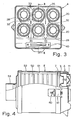
- the air pre-cleaner there illustrated is designated generally A.
- Figure 4 it is shown assembled with a filter F.
- the air pre-cleaner A comprises a shallow generally rectangular housing designated generally 1 consisting of an outer member 2 and an inner member 3 both moulded of plastics material.
- the housing 1 covers the end of the enclosure formed by the filter F.
- the outer member 2 comprises an outer end wall 4 and a peripheral wall 5 of generally rectangular formation as seen in end elevation.
- the inner housing wall 3 is located by and secured to a step 6 on the peripheral wall 5 of the outer member.
- the peripheral wall 5 extends beyond the step 6 to form a skirt 7.
- the end wall 4 of the outer housing member 2 is apertured at 4a to receive three generally similar inlet elements each designated generally 10 and defining a pair of annular inlets 11.
- the inlet elements 10 are arranged parallel in three rows (the rows are upright as shown in Figures 1 and 3).
- the inlet elements 10 may be plastics mouldings.
- the annular inlets 11 are axially aligned respectively with outlet openings 12 defined by flared portions 12a in the inner housing wall 3, with the axes parallel and perpendicular to the general plane of the end wall 4.
- the flared portion 12a forms a diffuser for air leaving the outlet openings 12.
- Each inlet element 10 comprises a flat connecting body 13 with a cylindrical flange 14 at each end. Vanes 15 extending radially inward from the flange support a central dome 16.
- the flange 14 and dome 16 define the annular inlet 11, and the vanes 15 are angled so as to impose a spin in the direction of the arrows 17 upon air entering the inlet.
- the vanes 15 are so formed as to cause the spin directions at the inlets 11 of each inlet element 10 to be contrary. Also the spin directions at adjacent inlets of adjacent inlet elements are contrary (see Figure 1).
- the outer housing member 2 is formed with deep tubular flanges 20 aligned with the corresponding inlets 11 and outlets 12.
- the inner housing member 3 rests against the ends of the flanges 20.
- the inlet elements 10 seat on the end wall 4 of the outer housing member 2, with the flanges 14 on the elements 10 extending within the flanges 20 on the member 2.
- a circular bead 26 on the end wall 4 within each of the tubular flanges 20 is received within'a corresponding annular recess 27 around each flange 14, for snap-action assembly of each inlet element 10 on the end wall 4; the arrangement also forms an air seal.
- each tubular flange 20 is cut away at its outer end to form a dust exit 28.
- the arrangement of the dust exits 28-in the dust chamber are shown in Figure 3.
- the flanges 20 are bevelled where they define opposite edges of the exit.
- each flange 14, flange 20, and outlet 12, form a tubular dust separator designated generally 30 with a peripheral step 31.
- the effect of the step 31 is to create a low-pressure area to assist in removing the spinning dust from the airstream and to reduce the overall pressure loss as the air passes through the dust separator 30.
- the dust follows the wall of the tubular flange 20 with a spiral motion until it reaches the exit 28 and passes as shown by arrow 32 into the dust chamber formed by the interior of the housing 1.
- the spinning air within the dust separator 30 in the region of the dust exit 28 tends to entrain the air in the dust chamber to move in a similar direction. If the air flows inside and outside the dust exit 28 correspond, turbulence in that region is minimised. There is no net air movement through the dust exit 28 since there is no scavenge flow. Turbulence at the dust exit has been found to inhibit dust rejection to a surprising extent, and hence the importance of avoiding conflicting air flows in the dust chamber and ensuring that air movement in the chamber outside each exit is in the same direction as air flow within it.
- the lower portion of the peripheral wall 5 of-the outer housing member 2 is angled as illustrated and apertured to mount an elastomeric dust valve member 40 having outwardly directed elastically sealing valve lips 41 and a base flange 42 secured to the wall 5 about the aperture. Dust falls to the bottom of the dust chamber formed by the interior of the housing 1 and when there is a sufficient weight of dust overlying the valve member 40 the valve opens to let the dust fall out.
- FIG 4 shows the air pre-cleaner A assembled with a filter F.
- the filter F comprises a deep pleated panel type filter element 50 with elastomeric walls 51 within a casing 52 having an outlet 53 at the end opposite the pre-cleaner.
- the skirt 7 of the air pre- cleaner fits around the periphery of the filter casing 52.
- the air pre-cleaner A is removably held to the filter casing 52 by a nut and bolt arrangement 60 on each side of the casing which acts on ledges 61 formed in the peripheral wall 5 of the outer housing member 2:
- the elastomeric end flanges of the filter element 50 are compressed against the inner housing wall 3 to form a seal which prevents any of the air entering the filter F from leaking around the outside of the cartridge 50.
- the air pre-cleaner A is simple to manufacture from relatively few parts. Main parts are the outer and inner housing walls 2, 3, and the identical inlet elements 10. Three simple mouldings only are needed. Although designed for use on the pleated paper filter shown, it could be used on other filters or by itself.
- the'outer housing wall 2 can be made of sheet metal. While the inlet elements 10 described each provide two inlets, it will be understood that each element could be made to provide three or more. Three inlets could be arranged in a line on one element. Four inlets could be arranged in a square on one element. Alternatively single-inlet elements are envisaged. Such elements could in a single generally tubular moulding provide the stepped flanges 14, 20, the vanes 15 and the dome 16, and be a snap fit in the outer end wall 4.
- the number of inlets 11 can vary depending on the expected volume of air flow. In one design according to the invention each inlet can handle about 25 cubic feet of air per minute. Thus, for a pre-cleaner designed for use with a small i.c. engine, three inlets might suffice. For greater flow requirements twelve or more might be used. While, especially with larger numbers, it is preferred to arrange the inlets in rows, with all inlets of each row similar-handed and left- and right-handed rows alternating, this is not absolutely necessary. For any inlet arrangement baffles can be provided, suitably designed to avoid turbulence in the dust space.
- FIGS to 7 show a second and preferred embodiment of the invention.
- the same reference numerals are used as in Figures 1 to 4 and no further description will be needed.
- the six dust separator elements 130 are in staggered rows so as to take less space.
- the elements 130 in each row have their direction of spin of the same hand, and the elements are right-handed, left-handed and right-handed going across the rows as seen in Figure 5.
- the construction of the pre-cleaner A' differs from that of the earlier figures also in being essentially a two-piece construction of outer and inner members 102,103 with the outer member having the domes 16 and vanes 15 formed integrally.
- the pre-cleaner A' can be designed for any number of dust separator elements 130 in a row.
- the air pre-cleaner A' can be used with a filter as shown in Figure 4 for the pre-cleaner A.
- the ratio length of air separator to width at its widest point is less than 1 in both pre-cleaners described. Without the arrangements described for minimising turbulence in the dust chamber this ratio would lead-to poor dust separation: the strongly rotating air at the dust exit would set up turbulence that would inhibit dust rejection through the dust outlet. While the exit has been shown as subtending 60° at the axis, this angle could be somewhat greater or less between the limits of, say, 45° and 90°.. Too large an angle would make it more difficult to control turbulence, while with too small an angle the dust could not escape freely.
- the dust separator elements have an. inlet 11 extending about 40% of the total area.
- a smaller inlet with faster flow, will tend to improve efficiency of dust separation but too small an inlet will impose resistance to flow: the ratio chosen is a compromise.
- a circulatory flow can, if desired, be provided by forming an opening to the dust chamber adjacent the step 31. Some air then enters the separator element at this point, and causes a small air outflow through the dust exit 28.
- baffles of circular outline may be provided in the centre of every four-element group.
Landscapes
- Chemical & Material Sciences (AREA)
- Chemical Kinetics & Catalysis (AREA)
- Filtering Of Dispersed Particles In Gases (AREA)
Applications Claiming Priority (2)
| Application Number | Priority Date | Filing Date | Title |
|---|---|---|---|
| GB8024022 | 1980-07-23 | ||
| GB8024022 | 1980-07-23 |
Publications (2)
| Publication Number | Publication Date |
|---|---|
| EP0044720A2 true EP0044720A2 (de) | 1982-01-27 |
| EP0044720A3 EP0044720A3 (de) | 1982-05-12 |
Family
ID=10514956
Family Applications (1)
| Application Number | Title | Priority Date | Filing Date |
|---|---|---|---|
| EP81303284A Withdrawn EP0044720A3 (de) | 1980-07-23 | 1981-07-16 | Luftreiniger |
Country Status (11)
| Country | Link |
|---|---|
| EP (1) | EP0044720A3 (de) |
| JP (1) | JPS5756657A (de) |
| KR (1) | KR830005886A (de) |
| AR (1) | AR223933A1 (de) |
| AU (1) | AU7330481A (de) |
| BR (1) | BR8104759A (de) |
| CA (1) | CA1176184A (de) |
| ES (1) | ES8205360A1 (de) |
| GB (1) | GB2080155B (de) |
| PT (1) | PT73411B (de) |
| ZA (1) | ZA814975B (de) |
Cited By (5)
| Publication number | Priority date | Publication date | Assignee | Title |
|---|---|---|---|---|
| FR2541587A1 (fr) * | 1983-02-28 | 1984-08-31 | Condair Ag | Procede et dispositif pour separer des impuretes d'un flux de gaz |
| DE3407219A1 (de) * | 1983-02-28 | 1984-12-06 | Condair AG, Münchenstein | Vorrichtung und verfahren zum abscheiden von fremdstoffen aus einem gasstrom |
| KR100445381B1 (ko) * | 2001-11-16 | 2004-08-25 | 한국과학기술연구원 | 자동세정형 충돌점착식 공기여과장치용 기류균일화장치 및그를 포함하는 공기여과장치 |
| US9993763B2 (en) | 2002-04-04 | 2018-06-12 | Donaldson Company, Inc. | Filter elements; air cleaner; assembly; and, methods |
| CN113958432A (zh) * | 2021-10-25 | 2022-01-21 | 无锡亿利环保科技有限公司 | 空气预滤组件、空气预滤器总成 |
Families Citing this family (2)
| Publication number | Priority date | Publication date | Assignee | Title |
|---|---|---|---|---|
| JP2507606Y2 (ja) * | 1990-07-06 | 1996-08-14 | 株式会社小松製作所 | 大型ダンプトラックの駆動系の冷却装置用エアクリ―ナ |
| DE102005031059A1 (de) * | 2005-07-02 | 2007-01-04 | Mahle International Gmbh | Als Vorfilter dienender Gaseintrittsbereich eines Gasfiltergehäuses |
Family Cites Families (6)
| Publication number | Priority date | Publication date | Assignee | Title |
|---|---|---|---|---|
| US2004468A (en) * | 1932-04-02 | 1935-06-11 | Centrifix Corp | Centrifugal separator |
| US2201301A (en) * | 1937-03-30 | 1940-05-21 | Western Precipitation Corp | Centrifugal separating device |
| BE538153A (de) * | 1954-05-15 | |||
| US2866518A (en) * | 1954-07-06 | 1958-12-30 | Western Precipitation Corp | Apparatus for equalizing pressures in multiple cyclone dust collectors |
| US3915679A (en) * | 1973-04-16 | 1975-10-28 | Pall Corp | Vortex air cleaner array |
| DE2526056A1 (de) * | 1974-06-17 | 1976-01-02 | Bendix Corp | Vorrichtung zur abtrennung von schmutzstoffen |
-
1981
- 1981-07-16 GB GB8121904A patent/GB2080155B/en not_active Expired
- 1981-07-16 EP EP81303284A patent/EP0044720A3/de not_active Withdrawn
- 1981-07-21 ZA ZA814975A patent/ZA814975B/xx unknown
- 1981-07-22 ES ES504193A patent/ES8205360A1/es not_active Expired
- 1981-07-22 AU AU73304/81A patent/AU7330481A/en not_active Abandoned
- 1981-07-22 PT PT73411A patent/PT73411B/pt unknown
- 1981-07-22 CA CA000382295A patent/CA1176184A/en not_active Expired
- 1981-07-23 AR AR286177A patent/AR223933A1/es active
- 1981-07-23 KR KR1019810002675A patent/KR830005886A/ko not_active Ceased
- 1981-07-23 JP JP56116318A patent/JPS5756657A/ja active Pending
- 1981-07-23 BR BR8104759A patent/BR8104759A/pt unknown
Cited By (8)
| Publication number | Priority date | Publication date | Assignee | Title |
|---|---|---|---|---|
| FR2541587A1 (fr) * | 1983-02-28 | 1984-08-31 | Condair Ag | Procede et dispositif pour separer des impuretes d'un flux de gaz |
| DE3407219A1 (de) * | 1983-02-28 | 1984-12-06 | Condair AG, Münchenstein | Vorrichtung und verfahren zum abscheiden von fremdstoffen aus einem gasstrom |
| US4545792A (en) * | 1983-02-28 | 1985-10-08 | Condair Ag | Device and process for precipitating foreign matter from a gas stream |
| KR100445381B1 (ko) * | 2001-11-16 | 2004-08-25 | 한국과학기술연구원 | 자동세정형 충돌점착식 공기여과장치용 기류균일화장치 및그를 포함하는 공기여과장치 |
| US9993763B2 (en) | 2002-04-04 | 2018-06-12 | Donaldson Company, Inc. | Filter elements; air cleaner; assembly; and, methods |
| US10500533B2 (en) | 2002-04-04 | 2019-12-10 | Donaldson Company, Inc. | Filter elements; air cleaner; assembly; and, methods |
| US11161072B2 (en) | 2002-04-04 | 2021-11-02 | Donaldson Company, Inc. | Filter elements; air cleaner; assembly; and, methods |
| CN113958432A (zh) * | 2021-10-25 | 2022-01-21 | 无锡亿利环保科技有限公司 | 空气预滤组件、空气预滤器总成 |
Also Published As
| Publication number | Publication date |
|---|---|
| PT73411B (en) | 1982-11-10 |
| GB2080155B (en) | 1983-11-09 |
| AU7330481A (en) | 1982-01-28 |
| ES504193A0 (es) | 1982-06-01 |
| AR223933A1 (es) | 1981-09-30 |
| GB2080155A (en) | 1982-02-03 |
| EP0044720A3 (de) | 1982-05-12 |
| ZA814975B (en) | 1982-08-25 |
| JPS5756657A (en) | 1982-04-05 |
| BR8104759A (pt) | 1982-04-13 |
| ES8205360A1 (es) | 1982-06-01 |
| KR830005886A (ko) | 1983-09-14 |
| PT73411A (en) | 1981-08-01 |
| CA1176184A (en) | 1984-10-16 |
Similar Documents
| Publication | Publication Date | Title |
|---|---|---|
| US11585548B2 (en) | Air purifier with air outlet guider | |
| US4394145A (en) | Air cleaners | |
| US4242115A (en) | Air cleaner assembly | |
| US3078650A (en) | Air cleaner | |
| US10543442B2 (en) | Multiple stage rotating coalescer devices | |
| US3884658A (en) | Air cleaner for supercharged engines | |
| US4877431A (en) | Radial impingement separator | |
| US3423909A (en) | Air cleaner with improved filter element assembly | |
| CA1191753A (en) | Vortex air cleaner and self-cleaning barrier filter assembly for supercharged engines | |
| US4486206A (en) | Cyclone type air cleaner | |
| KR102160569B1 (ko) | 메쉬망을 포함한 블레이드 | |
| US4303423A (en) | Engine air cleaner | |
| US12172116B2 (en) | Air filter assembly with a permeable baffle | |
| CA1069001A (en) | Air cleaner with integral louvered precleaner | |
| GB2064359A (en) | Air filters | |
| EP0044720A2 (de) | Luftreiniger | |
| US4500332A (en) | Throughput blade for louvered separators | |
| US3339533A (en) | Air filter for internal combustion engines | |
| KR20190033891A (ko) | 집진장치 및 이를 구비하는 청소기 | |
| WO2022076416A1 (en) | Air cleaner with water separation | |
| US20060037908A1 (en) | Reverse flow fuel filter | |
| US3421294A (en) | Oil bath air cleaner | |
| CN118462441B (zh) | 滤清器 | |
| RU2015404C1 (ru) | Воздухоочиститель для двигателя внутреннего сгорания | |
| KR102368528B1 (ko) | 이물질 제거용 팬 블레이드 |
Legal Events
| Date | Code | Title | Description |
|---|---|---|---|
| PUAI | Public reference made under article 153(3) epc to a published international application that has entered the european phase |
Free format text: ORIGINAL CODE: 0009012 |
|
| AK | Designated contracting states |
Designated state(s): AT BE DE FR IT NL SE |
|
| PUAL | Search report despatched |
Free format text: ORIGINAL CODE: 0009013 |
|
| AK | Designated contracting states |
Designated state(s): AT BE DE FR IT NL SE |
|
| 17P | Request for examination filed |
Effective date: 19821106 |
|
| STAA | Information on the status of an ep patent application or granted ep patent |
Free format text: STATUS: THE APPLICATION IS DEEMED TO BE WITHDRAWN |
|
| 18D | Application deemed to be withdrawn |
Effective date: 19850128 |