EP0044469A1 - Bracket for the mounting of heating tubes on a floor - Google Patents
Bracket for the mounting of heating tubes on a floor Download PDFInfo
- Publication number
- EP0044469A1 EP0044469A1 EP81105319A EP81105319A EP0044469A1 EP 0044469 A1 EP0044469 A1 EP 0044469A1 EP 81105319 A EP81105319 A EP 81105319A EP 81105319 A EP81105319 A EP 81105319A EP 0044469 A1 EP0044469 A1 EP 0044469A1
- Authority
- EP
- European Patent Office
- Prior art keywords
- base part
- incisions
- extensions
- projections
- wire
- Prior art date
- Legal status (The legal status is an assumption and is not a legal conclusion. Google has not performed a legal analysis and makes no representation as to the accuracy of the status listed.)
- Withdrawn
Links
- 238000010438 heat treatment Methods 0.000 title claims abstract description 12
- 229910000746 Structural steel Inorganic materials 0.000 claims description 14
- 239000004744 fabric Substances 0.000 claims description 7
- 239000000463 material Substances 0.000 claims description 2
- 230000002787 reinforcement Effects 0.000 abstract 2
- 229910000831 Steel Inorganic materials 0.000 description 11
- 239000010959 steel Substances 0.000 description 11
- 235000000396 iron Nutrition 0.000 description 4
- XEEYBQQBJWHFJM-UHFFFAOYSA-N Iron Chemical compound [Fe] XEEYBQQBJWHFJM-UHFFFAOYSA-N 0.000 description 2
- 229910001209 Low-carbon steel Inorganic materials 0.000 description 2
- 238000005452 bending Methods 0.000 description 2
- 239000004698 Polyethylene Substances 0.000 description 1
- 240000000359 Triticum dicoccon Species 0.000 description 1
- 239000010426 asphalt Substances 0.000 description 1
- 238000010276 construction Methods 0.000 description 1
- 230000000694 effects Effects 0.000 description 1
- 230000002349 favourable effect Effects 0.000 description 1
- 229910052742 iron Inorganic materials 0.000 description 1
- -1 polyethylene Polymers 0.000 description 1
- 229920000573 polyethylene Polymers 0.000 description 1
- 230000003313 weakening effect Effects 0.000 description 1
Images
Classifications
-
- F—MECHANICAL ENGINEERING; LIGHTING; HEATING; WEAPONS; BLASTING
- F24—HEATING; RANGES; VENTILATING
- F24D—DOMESTIC- OR SPACE-HEATING SYSTEMS, e.g. CENTRAL HEATING SYSTEMS; DOMESTIC HOT-WATER SUPPLY SYSTEMS; ELEMENTS OR COMPONENTS THEREFOR
- F24D3/00—Hot-water central heating systems
- F24D3/12—Tube and panel arrangements for ceiling, wall, or underfloor heating
- F24D3/14—Tube and panel arrangements for ceiling, wall, or underfloor heating incorporated in a ceiling, wall or floor
- F24D3/141—Tube mountings specially adapted therefor
- F24D3/144—Clips for fastening heating tubes on a reinforcement net or mesh, e.g. mesh for concrete reinforcement
-
- F—MECHANICAL ENGINEERING; LIGHTING; HEATING; WEAPONS; BLASTING
- F16—ENGINEERING ELEMENTS AND UNITS; GENERAL MEASURES FOR PRODUCING AND MAINTAINING EFFECTIVE FUNCTIONING OF MACHINES OR INSTALLATIONS; THERMAL INSULATION IN GENERAL
- F16B—DEVICES FOR FASTENING OR SECURING CONSTRUCTIONAL ELEMENTS OR MACHINE PARTS TOGETHER, e.g. NAILS, BOLTS, CIRCLIPS, CLAMPS, CLIPS OR WEDGES; JOINTS OR JOINTING
- F16B7/00—Connections of rods or tubes, e.g. of non-circular section, mutually, including resilient connections
- F16B7/04—Clamping or clipping connections
-
- F—MECHANICAL ENGINEERING; LIGHTING; HEATING; WEAPONS; BLASTING
- F24—HEATING; RANGES; VENTILATING
- F24D—DOMESTIC- OR SPACE-HEATING SYSTEMS, e.g. CENTRAL HEATING SYSTEMS; DOMESTIC HOT-WATER SUPPLY SYSTEMS; ELEMENTS OR COMPONENTS THEREFOR
- F24D3/00—Hot-water central heating systems
- F24D3/12—Tube and panel arrangements for ceiling, wall, or underfloor heating
- F24D3/14—Tube and panel arrangements for ceiling, wall, or underfloor heating incorporated in a ceiling, wall or floor
- F24D3/141—Tube mountings specially adapted therefor
-
- Y—GENERAL TAGGING OF NEW TECHNOLOGICAL DEVELOPMENTS; GENERAL TAGGING OF CROSS-SECTIONAL TECHNOLOGIES SPANNING OVER SEVERAL SECTIONS OF THE IPC; TECHNICAL SUBJECTS COVERED BY FORMER USPC CROSS-REFERENCE ART COLLECTIONS [XRACs] AND DIGESTS
- Y02—TECHNOLOGIES OR APPLICATIONS FOR MITIGATION OR ADAPTATION AGAINST CLIMATE CHANGE
- Y02B—CLIMATE CHANGE MITIGATION TECHNOLOGIES RELATED TO BUILDINGS, e.g. HOUSING, HOUSE APPLIANCES OR RELATED END-USER APPLICATIONS
- Y02B30/00—Energy efficient heating, ventilation or air conditioning [HVAC]
Definitions
- the invention relates to a clamp for fastening floor heating pipes to a holding strip, consisting of a base part, a holding part for the pipes provided on the top thereof, which has holding projections extending therefrom, and a pair of clamping projections projecting downward from the base part Clamping on the retaining strip, wherein incisions are provided for receiving wires of a mild steel mesh.
- underfloor heating pipes can be attached to holding strips such as Band iron or can be attached to the wires of a steel mesh.
- this prior art clip has several disadvantages. If band irons are intended to hold the clamps and the heating pipes in place, the heating pipes can only be attached at a predetermined angle relative to the band irons if you do not want to provide different clamps for different angles, which of course means greater storage, greater costs and longer working hours Finding the right parentheses would mean. If e.g. a type of clamps is provided with which the heating pipes can be arranged perpendicular to the band irons, so if a parallel arrangement is also desired, a second set of corresponding clamps would have to be provided.
- Another disadvantage of the known clip is that it has to be attached to the structural steel mesh from below. On the one hand, this means the cumbersome work of first lifting the steel mesh, which is made even more difficult by the fact that the worker stands on this steel mesh. So he has to lift part of his weight, so to speak. In addition, there is a risk that when the clips are pushed in, the insulating cover underneath, such as, for. B. bitumen p appe or polyethylene film is damaged.
- the object of the invention is to provide an improved clip of the type mentioned, which is easier to attach and more versatile to use.
- the solution according to the invention is that four holding projections arranged with cross-shaped gaps are provided, that the incisions for receiving wires of the structural steel fabric are provided on the underside of the base part in the clamping projections, and that each of these two incisions has two extensions arranged one above the other.
- the clips can be attached to the wires of the structural steel mesh from above.
- the incisions have extensions that correspond to the cross-section of the wire, so that the clips hold the wire or the wire the clip very well on these extensions.
- the clip will have a certain elasticity so that after being pushed on the wires snap when they reach the extensions.
- Two extensions arranged one above the other are provided, which is important if the clip is to be fastened at crossing points of the structural steel mesh. If the wire over which the incisions are pushed is the upper one at this crossing point, the clamp can be pressed down so far that the wire snaps into the upper extension. However, if the incisions are to be pushed over the lower wire, the clip is pushed over the wire up to the lower extension. In this way, there is still space between the lower wire and a lower surface of the clamp for receiving the upper wire at the crossing point.
- the extensions can be circular cutouts. This shape is particularly advantageously adapted to the usual shape of structural steel wires which have a substantially circular cross section.
- each incision can be immediately adjacent to one another.
- the distance between the centers of the extensions corresponds approximately to the diameter the extension and thus the wire diameter.
- a shift from the lower extension to the upper extension therefore corresponds to the thickness of the wire.
- the lower surface of the base part can, apart from the clamping projections, be designed to be flat. It will have a certain minimum thickness to achieve appropriate stability.
- the lower surface of the base part, against which the wire can rest forms the groove base of two grooves running in a cross shape in the direction of the incisions or perpendicularly thereto on the underside of the base part. In this way it is achieved that the base part is weakened on two perpendicular lines so that it can be bent more easily there. This makes it easier to slide the clip over the steel mesh. The incisions open more easily because the entire base part is deformed accordingly.
- the remaining thickness of the base part should be approximately 2.5 mm in order to achieve a favorable bending behavior in the area of the grooves.
- the clip according to the invention has an essentially rectangular or square plate-shaped base part 1, from which four holding projections 2 extend upwards at the corners. Between every two adjacent retaining projections there is an equally large space between which a heating pipe 3 can be held. The heating pipe can be held in two positions in which its axis has the direction AA or BB in Fig. 3. You can do it still locking projections 4 may be provided on the holding projections 2, with which the tube between the holding projections is held better. Under the base there are two clamping projections 5 with correspondingly hook-shaped lower edges on two opposite longitudinal sides of the base part, which can be pushed over a retaining bar 6 so that the clip engages thereon. In the middle of the clamping projections 5, notches 7 are provided with two extensions, which have approximately the shape and cross-sectional area of structural steel wires 8.
- the upper extension holds the upper wire which penetrates into a groove 9 running centrally in the underside of the base part 1.
- the upper wire of the structural steel fabric, which is not held by the incision 7 is in the groove 10 perpendicular thereto, while the lower wire of the structural steel fabric is held by the incisions 7 with the lower extension.
- the grooves 9 and 10 and the resulting weakening of the base part in these areas result in increased flexibility of the base part, for example, about the lines A-A and B-B in FIG. 3. This flexibility makes it easier to snap the clip onto a steel strip or a mild steel wire. In addition, due to this flexibility, the tube can be inserted more easily into the clamp.
Abstract
Description
Die Erfindung betrifft eine Klammer zum Befestigen von Fußboden-Heizungsrohren an einer Halteleiste, bestehend aus einem Basisteil, einem auf dessen Oberseite vorgesehenen Halteteil für die Rohre, der von derselben sich erstreckende Haltevorsprünge aufweist, und einem von dem Basisteil nach unten abstehenden Paar von Klemmvorsprüngen zum Festklemmen auf der Halteleiste, wobei Einschnitte zum Aufnehmen von Drähten eines Baustahlgewebes vorgesehen sind.The invention relates to a clamp for fastening floor heating pipes to a holding strip, consisting of a base part, a holding part for the pipes provided on the top thereof, which has holding projections extending therefrom, and a pair of clamping projections projecting downward from the base part Clamping on the retaining strip, wherein incisions are provided for receiving wires of a mild steel mesh.
Mit einer Klammer dieser Art (DE-GM 75 30 180) können Fußboden-Heizungsrohre an Halteleisten wie z.B. Bandeisen oder aber an den Drähten eines Baustahlgewebes befestigt werden.With this type of clamp (DE-GM 75 30 180), underfloor heating pipes can be attached to holding strips such as Band iron or can be attached to the wires of a steel mesh.
Diese vorbekannte Klammer hat jedoch verschiedene Nachteile. Sind Bandeisen für das Festhalten der Klammern und der Heizungsrohre vorgesehen, so können die Heizungsrohre nur in einem vorgegebenen Winkel relativ zu den Bandeisen befestigt werden, wenn man nicht für verschiedene Winkel verschiedene Klammern vorsehen will, was natürlich größere Lagerhaltung, größere Kosten und längere Arbeitszeit beim Heraussuchen der richtigen Klammern bedeuten würde. Wenn z.B. eine Art von Klammern vorgesehen ist, mit denen die Heizungsrohre senkrecht zu den Bandeisen angeordnet werden können, so müßte, wenn auch parallele Anordnung gewünscht wird, noch ein zweiter Satz entsprechender Klammern vorgesehen sein.However, this prior art clip has several disadvantages. If band irons are intended to hold the clamps and the heating pipes in place, the heating pipes can only be attached at a predetermined angle relative to the band irons if you do not want to provide different clamps for different angles, which of course means greater storage, greater costs and longer working hours Finding the right parentheses would mean. If e.g. a type of clamps is provided with which the heating pipes can be arranged perpendicular to the band irons, so if a parallel arrangement is also desired, a second set of corresponding clamps would have to be provided.
Wird die vorbekannte Klammer auf Drähte eines Baustahlgewebes gesetzt, so sind zwar zwei verschiedene Winkeleinstellungen zwischen den Drähten und den Heizungsrohren möglich. Zur Änderung dieser Winkeleinstellung ist es jedoch erforderlich, die Klammer so zu versetzen, daß sie in die richtige Richtung zeigt.If the previously known clamp is placed on wires of a structural steel mesh, two different angle settings are possible between the wires and the heating pipes. To change this angle setting, however, it is necessary to move the bracket so that it points in the correct direction.
Ein weiterer Nachteil der vorbekannten Klammer besteht darin, daß sie von unten an dem Baustahlgewebe befestigt werden muß. Dies bedeutet einmal die umständliche Arbeit, zunächst das Baustahlgewebe anzuheben, was noch dadurch erschwert wird, daß der Arbeiter auf diesem Baustahlgewebe steht. Er muß also sozusagen einen Teil seines Gewichtes anheben. Außerdem besteht die Gefahr, daß beim Unterschieben der Klammern die darunterliegende Isolierabdeckung wie z. B. Bitumenpappe oder Polyäthylenfolie beschädigt wird.Another disadvantage of the known clip is that it has to be attached to the structural steel mesh from below. On the one hand, this means the cumbersome work of first lifting the steel mesh, which is made even more difficult by the fact that the worker stands on this steel mesh. So he has to lift part of his weight, so to speak. In addition, there is a risk that when the clips are pushed in, the insulating cover underneath, such as, for. B. bitumen p appe or polyethylene film is damaged.
Die Aufgabe der Erfindung besteht darin, eine verbesserte Klammer der eingangs genannten Art zu schaffen, die leichter anzubringen und vielseitiger zu verwenden ist.The object of the invention is to provide an improved clip of the type mentioned, which is easier to attach and more versatile to use.
Die erfindungsgemäße Lösung besteht darin, daß vier mit kreuzförmigen Zwischenräumen angeordnete Haltevorsprünge vorgesehen sind, daß die Einschnitte für die Aufnahme von Drähten des Baustahlgewebes auf der Unterseite des Basisteiles in den Klemmvorsprüngen vorgesehen sind, und daß jeder dieser beiden Einschnitte zwei übereinander angeordnete Erweiterungen aufweist.The solution according to the invention is that four holding projections arranged with cross-shaped gaps are provided, that the incisions for receiving wires of the structural steel fabric are provided on the underside of the base part in the clamping projections, and that each of these two incisions has two extensions arranged one above the other.
Während die vorbekannte Klammer zwei längliche Haltevorsprünge hatte, zwischen denen das Rohr in der Richtung der Längserstreckung der Haltevorsprünge eingeklemmt wurde, sind hier vier Haltevorsprünge vorgesehen. Das Rohr kann zwischen diese vier Haltevorsprünge in einer ersten Stellung und einer zweiten dazu senkrechten Stellung eingeklemmt werden. Es befinden sich dann jeweils auf jeder Seite des Rohres zwei Haltevorsprünge, während das Rohr an zwei Stellen von auf verschiedenen Seiten des Rohres angeordneten Haltevorsprüngen festgehalten wird. Man braucht daher beim Aufstecken der Klammern auch die Bandeisen oder die Drähte des Baustahlgewebes noch nicht zu berücksichtigen, ob die Rohre in einer Richtung oder in einer dazu senkrechten Richtung später befestigt werden sollen. Man kann die Klammern vielmehr in der Stellung oder dazu um 90° gedrehten Stellung aufstecken, die gerade am günstigsten ist.While the previously known clamp had two elongated holding projections, between which the tube was clamped in the direction of the longitudinal extension of the holding projections, four holding projections are provided here. The tube can be clamped between these four holding projections in a first position and a second position perpendicular thereto. There are then two holding projections on each side of the tube, while the tube is held in two places by holding projections arranged on different sides of the tube. Therefore, when attaching the clips, you do not have to take into account the band irons or the wires of the structural steel mesh, whether the pipes should be attached in one direction or in a direction perpendicular to them later. One can rather put the brackets in position or plug it into the 90 ° rotated position that is currently the cheapest.
Dadurch, daß die Einschnitte für die Aufnahme von Drähten des Baustahlgevebes. auf der unteren Seite des Basisteils und zwar in den Klemmvorsprüngen vorgesehen sind, können die Klammern von oben auf die Drähte des Baustahlgewebes aufgesteckt werden. Die Einschnitte weisen dabei Erweiterungen auf, die dem Querschnitt des Drahtes entsprechen, so daß an diesen Erweiterungen die Klammer den Draht bzw. der Draht die Klammer sehr gut festhält.. Die Klammer wird dabei eine gewisse Elastizität haben, so daß sie nach dem Aufschieben auf die Drähte, wenn dieselben die Erweiterungen erreichen, einschnappt. Es sind dabei zwei übereinander angeordnete Erweiterungen vorgesehen, was von Bedeutung ist, wenn die Klammer an Kreuzungspunkten des Baustahlgewebes befestigt werden soll. Ist an diesem Kreuzungspunkt der Draht, über den die Einschnitte geschoben werden, der obere, so kann die Klammer so weit herabgedrückt werden, daß der Draht in der oberen Erweiterung einrastet. Sollen jedoch die Einschnitte über den unteren Draht geschoben werden, so wird die Klammer bis zur unteren Erweiterung über den Draht geschoben. Auf diese Weise verbleibt zwischen unterem Draht und einer Unterfläche der Klammer noch Raum für die Aufnahme des oberen Drahtes an der Kreuzungsstelle.The fact that the incisions for receiving wires of the structural steel. on the lower side of the base part and that are provided in the clamping projections, the clips can be attached to the wires of the structural steel mesh from above. The incisions have extensions that correspond to the cross-section of the wire, so that the clips hold the wire or the wire the clip very well on these extensions. The clip will have a certain elasticity so that after being pushed on the wires snap when they reach the extensions. Two extensions arranged one above the other are provided, which is important if the clip is to be fastened at crossing points of the structural steel mesh. If the wire over which the incisions are pushed is the upper one at this crossing point, the clamp can be pressed down so far that the wire snaps into the upper extension. However, if the incisions are to be pushed over the lower wire, the clip is pushed over the wire up to the lower extension. In this way, there is still space between the lower wire and a lower surface of the clamp for receiving the upper wire at the crossing point.
Die Erweiterungen können kreisförmig begrenzte Aussparungen sein. Diese Form ist besonders günstig der üblichen Form von Baustahldrähten angepaßt, die im wesentlichen kreisförmigen Querschnitt haben.The extensions can be circular cutouts. This shape is particularly advantageously adapted to the usual shape of structural steel wires which have a substantially circular cross section.
Die Erweiterungen jedes Einschnitts können einander unmittelbar benachbart sein. In diesem Falle entspricht der Abstand der Mittelpunkte der Erweiterungen ungefähr dem Durchmesser der Erweiterung und damit den Drahtdurchmesser. Eine Verschiebung von der unteren Erweiterung zur oberen Erweiterung entspricht daher der Dicke des Drahtes. Liegt bei Halten des Drahtes in der oberen Erweiterung der Draht an der Unterfläche des Basisteiles an, so wird der obere Draht an einem reuzengspunkt ebenfalls an der Basisfläche anliegen, wenn der untere Draht in den unteren Erweiterungen gehalten wird. In beiden Fällen kann, wenn die Unterseite des Basisteiles hier oben ist, das Klammerelement so gut gegen Kippen gesichert werden, da es jedenfalls auf einer geraden Berührungslinie auf den Draht auflieft. Dies ist dann der Fall, wenn die oberen Erweiterungen an den basisteilseitigen Enden der Einschnitte unmittelbar unter einer Unterfläche des Basisteils angeordnet sind.The extensions of each incision can be immediately adjacent to one another. In this case, the distance between the centers of the extensions corresponds approximately to the diameter the extension and thus the wire diameter. A shift from the lower extension to the upper extension therefore corresponds to the thickness of the wire. If the wire is in contact with the lower surface of the base part when the wire is held in the upper extension, the upper wire will also lie against the base surface at a reuzengpunkt when the lower wire is held in the lower extensions. In both cases, if the underside of the base part is up here, the clamp element can be secured against tipping so well, since it in any case strikes the wire on a straight line of contact. This is the case when the upper extensions on the base part ends of the incisions are arranged directly under a lower surface of the base part.
Die Unterfläche des Basisteils kann, bis auf die Klemmvorsprünge, an sich eben gestaltet werden. Sie wird dabei zum Erzielen einer entsprechenden Stabilität eine gewisse Mindestdicke haben. Es kann jedoch auch vorgesehen sein, daß die Unterfläche des Basisteiles,an der der Draht anliegen kann, den Nutengrund von zwei kreuzförmig in Richtung der Einschnitte bzw. senkrecht dazu auf der Unterseite des Basisteils verlaufenden Nuten bildet. Auf diese Weise wird erreicht, daß der Basisteil an zwei zueinander senkrechten Linien so geschwächt ist, daß er dort leichter gebogen werden kann. Die Klammer kann so leichter über das Baustahlgewebe geschoben werden. Die Einschnitte öffnen sich nämlich leichter, da der gesamte Basisteil entsprechend deformiert wird. Dabei wird man natürlich die Restdicke des Basisteils so groß vorsehen, daß durch die Rückfederkraft ein genügend fester Halt der Klammer auf dem Draht des Baustahlgewebes sichergestellt ist. Eine zusätzliche Haltewirkung wird erreicht, wenn im oberen Teil das Rohr aufgeschoben bzw. eingeschoben wird, da diese Deformation der Deformation durch den eingeführten Baustahldraht entgegengesetzt ist. Außerdem wird durch diese Biegelinien natürlich auch das Aufschieben des Rohres erleichtert. Schließlich wind selbstverständlich auch, wenn die Klammer auf einen Bandstahl aufgeschoben wird, das Aufschieben und Einschnappen hierdurch erleichtert. Die restliche Materialdicke des Basisteils sollte zur Erzielung eines günstigen Biegeverhaltens im Bereich der Nuten ungefähr 2,5 mm betragen.The lower surface of the base part can, apart from the clamping projections, be designed to be flat. It will have a certain minimum thickness to achieve appropriate stability. However, it can also be provided that the lower surface of the base part, against which the wire can rest, forms the groove base of two grooves running in a cross shape in the direction of the incisions or perpendicularly thereto on the underside of the base part. In this way it is achieved that the base part is weakened on two perpendicular lines so that it can be bent more easily there. This makes it easier to slide the clip over the steel mesh. The incisions open more easily because the entire base part is deformed accordingly. It will of course provide the remaining thickness of the base part so large that the spring back ensures a sufficiently firm hold of the clip on the wire of the steel fabric. An additional holding effect is achieved if the tube is pushed or pushed in the upper part, since this deformation is opposite to the deformation caused by the inserted structural steel wire. Besides, will these bending lines also make it easier to push on the pipe. Finally, of course, when the clip is slid onto a steel strip, this makes it easier to slide on and snap into place. The remaining material thickness of the base part should be approximately 2.5 mm in order to achieve a favorable bending behavior in the area of the grooves.
Die Erfindung wird im folgenden beispielsweise anhand einer vorteilhaften Ausführungsform unter Bezugnahme auf die Zeichnungen beschrieben. Es zeigen:
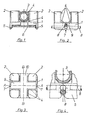
- Fig. 1 eine Seitenansicht einer K]ammer, die auf einen Bandstahl aufgeschoben ist und ein Heizungsrohr hält;
- Fig. 2 eine um 90° gegenüber Fig. 1 gedrehte Seitenansicht einer Klammer, die im Kreuzungspunkt der Drähte auf ein Bausthlgewebe aufgeschoben ist;
- Fig. 3 eine Ansicht von oben der erfindungsgemäßen Klammer; und
- Fig. 4 eine vergrößerte Detailansicht der Klammer wie in der Stellung der Fig. 2, wobei die Klammer jedoch in anderer Weise auf den Kreuzungspunkt des Baustahlgewebes aufgesetzt ist.
- Fig. 1 is a side view of a chamber, which is pushed onto a steel strip and holds a heating pipe;
- Fig. 2 is a side view rotated by 90 ° with respect to Fig. 1 of a clip which is pushed onto a construction steel fabric at the point of intersection of the wires;
- 3 is a top view of the clip according to the invention; and
- Fig. 4 is an enlarged detail view of the clip as in the position of Fig. 2, but the clip is placed in a different way on the intersection of the steel mesh.
Die erfindungsgemäße Klammer weist einen im wesentlichen rechteckigen oder quadratischen plattenförmigen Basisteil 1 auf, von dem sich nach oben an den Ecken vier Haltevorsprünge 2 erstrecken. Zwischen je zwei benachbarten Haltevorsprüngen befindet sich ein gleich großer Zwischenraum, zwischen denen ein Heizungsrohr 3 festgehalten werden kann. Das Heizungsrohr kann dabei in zwei Stellungen festgehalten werden, in denen seine Achse die Richtung A-A oder B-B in Fig. 3 hat. Es können dabei noch Rastvorsprünge 4 an den Haltevorsprüngen 2 vorgesehen sein, mit denen das Rohr zwischen den Haltevorsprüngen besser festgehalten wird. Unter der Basis befinden sich auf zwei gegen- überljegenden Längsseiten des Basisteils zwei Klemmvorsprünge 5 mit entsprechend hakenförmig ausgebildeten Unterkanten, die über eine Halteleiste 6 geschoben werden können, so daß die Klammer auf derselben einrastet. In der Mitte der Klemmvorsprünge 5 sind Einschnitte 7 mit zwei Erwejterungen vorgesehen, die ungefähr die Form wie die Querschnittsfläche von Baustahldrähten 8 haben.The clip according to the invention has an essentially rectangular or square plate-
In den Fig. 2 und 4 ist gezeigt, wie die Klamner auf zwei verschiedene Weisen auf den Kreuzungspunkt eines Baustahlgewebes gesetzt werden kann. Bei der Darstellung der Fig. 2 hält die obere Erweiterung den oberen Draht fest, der dabei in eine mittig in der Unterseite des Basisteils 1 verlaufende Nut 9 eindringt. Bei der anderen Stellung der Fig. 4 befindet sich der obere Draht des Baustahlgewebes, der nicht von dem Einschnitt 7 festgehalten wird, in der dazu senkrechten Nut 10, während der untere Draht des Baustahlgewebes durch die Einschnitte 7 mit der unteren Erweiterung festgehalten wird.2 and 4 show how the clamp can be placed in two different ways at the crossover point of a steel mesh. 2, the upper extension holds the upper wire which penetrates into a
Durch die Nuten 9 bzw. 10 und die dadurch bewirkte Schwächung des Basisteils in diesen Bereichen wird eine erhöhte Biegbarkeit des Basisteiles etwa um die Zinien A-A bzw. B-B in Fig. 3 bewirkt. Aufgrund dieser Biegbarkeit kann die Klammer leichter auf einen Bandstahl oder einen Baustahldraht aufgeschnappt werden. Außerdem kann aufgrund dieser Biegbarkeit leichter das Rohr in die Klammer eingeschoben werden.The
Claims (6)
Applications Claiming Priority (2)
| Application Number | Priority Date | Filing Date | Title |
|---|---|---|---|
| DE8019598U | 1980-07-22 | ||
| DE8019598U DE8019598U1 (en) | 1980-07-22 | 1980-07-22 | Clamp for fastening underfloor heating pipes |
Publications (1)
| Publication Number | Publication Date |
|---|---|
| EP0044469A1 true EP0044469A1 (en) | 1982-01-27 |
Family
ID=6717405
Family Applications (1)
| Application Number | Title | Priority Date | Filing Date |
|---|---|---|---|
| EP81105319A Withdrawn EP0044469A1 (en) | 1980-07-22 | 1981-07-09 | Bracket for the mounting of heating tubes on a floor |
Country Status (3)
| Country | Link |
|---|---|
| EP (1) | EP0044469A1 (en) |
| DE (1) | DE8019598U1 (en) |
| DK (1) | DK325081A (en) |
Cited By (11)
| Publication number | Priority date | Publication date | Assignee | Title |
|---|---|---|---|---|
| AT380734B (en) * | 1984-06-05 | 1986-06-25 | Kramer Karl | CLAMP FOR FASTENING PIPES OF AN UNDERFLOOR HEATING |
| DE9403449U1 (en) * | 1994-03-01 | 1994-04-28 | Missel Gmbh & Co E | Mounting clamp |
| EP1719954A1 (en) * | 2005-05-06 | 2006-11-08 | REHAU AG + Co | Polymeric fastening rail for receiving conduits conducting a fluid |
| DE102009023178A1 (en) * | 2009-05-29 | 2010-12-02 | Rehau Ag + Co. | Fixing system for fixing e.g. cables, of under-floor heater on steel lattice mat, has fixing clips molded as magazine by fixing frame such that magazine is pushed onto insertion area of setting rod |
| CN102852220A (en) * | 2011-06-28 | 2013-01-02 | 天津万联管道工程有限公司 | Prefabricated grating well |
| WO2013058656A1 (en) * | 2011-10-21 | 2013-04-25 | Michiels Management B.V. | Pipe clamp |
| US10408469B2 (en) | 2014-08-18 | 2019-09-10 | Progress Profiles Spa | Method and apparatus for positioning heating elements |
| US10502434B2 (en) | 2016-04-01 | 2019-12-10 | Progress Profiles S.P.A. | Support for radiant covering and floor heating elements |
| CN111664492A (en) * | 2020-07-14 | 2020-09-15 | 俞启鸿 | Heat exchange station heating pipe network |
| US10859274B2 (en) | 2016-04-01 | 2020-12-08 | Progress Profiles S.P.A. | Support for radiant covering and floor heating elements |
| US11041638B2 (en) | 2009-08-28 | 2021-06-22 | Progress Profiles Spa | Method and apparatus for positioning heating elements |
Families Citing this family (2)
| Publication number | Priority date | Publication date | Assignee | Title |
|---|---|---|---|---|
| DE3032958C2 (en) * | 1980-09-02 | 1984-12-20 | Ta Rokal GmbH, 4330 Mülheim | Spacers for heating pipes |
| CH665667A5 (en) * | 1984-03-06 | 1988-05-31 | Manfred Fennesz | INSULATING PLATE ARRANGEMENT. |
Citations (1)
| Publication number | Priority date | Publication date | Assignee | Title |
|---|---|---|---|---|
| CH595596A5 (en) * | 1975-09-24 | 1978-02-15 | Zeigmeister H Nordrohr Kunstst | Bracket for holding floor heating tubes |
-
1980
- 1980-07-22 DE DE8019598U patent/DE8019598U1/en not_active Expired
-
1981
- 1981-07-09 EP EP81105319A patent/EP0044469A1/en not_active Withdrawn
- 1981-07-21 DK DK325081A patent/DK325081A/en not_active Application Discontinuation
Patent Citations (1)
| Publication number | Priority date | Publication date | Assignee | Title |
|---|---|---|---|---|
| CH595596A5 (en) * | 1975-09-24 | 1978-02-15 | Zeigmeister H Nordrohr Kunstst | Bracket for holding floor heating tubes |
Cited By (17)
| Publication number | Priority date | Publication date | Assignee | Title |
|---|---|---|---|---|
| AT380734B (en) * | 1984-06-05 | 1986-06-25 | Kramer Karl | CLAMP FOR FASTENING PIPES OF AN UNDERFLOOR HEATING |
| DE9403449U1 (en) * | 1994-03-01 | 1994-04-28 | Missel Gmbh & Co E | Mounting clamp |
| EP1719954A1 (en) * | 2005-05-06 | 2006-11-08 | REHAU AG + Co | Polymeric fastening rail for receiving conduits conducting a fluid |
| DE102009023178A1 (en) * | 2009-05-29 | 2010-12-02 | Rehau Ag + Co. | Fixing system for fixing e.g. cables, of under-floor heater on steel lattice mat, has fixing clips molded as magazine by fixing frame such that magazine is pushed onto insertion area of setting rod |
| US11846432B2 (en) | 2009-08-28 | 2023-12-19 | Progress Profiles Spa | Method and apparatus for positioning heating elements |
| US11041638B2 (en) | 2009-08-28 | 2021-06-22 | Progress Profiles Spa | Method and apparatus for positioning heating elements |
| CN102852220A (en) * | 2011-06-28 | 2013-01-02 | 天津万联管道工程有限公司 | Prefabricated grating well |
| US9857086B2 (en) | 2011-10-21 | 2018-01-02 | Q-Clip B.V. | Pipe clamp |
| CN103958952B (en) * | 2011-10-21 | 2016-12-07 | Q-科利普有限公司 | Pipe clamp |
| CN103958952A (en) * | 2011-10-21 | 2014-07-30 | Q-科利普有限公司 | Pipe clamp |
| WO2013058656A1 (en) * | 2011-10-21 | 2013-04-25 | Michiels Management B.V. | Pipe clamp |
| US10408469B2 (en) | 2014-08-18 | 2019-09-10 | Progress Profiles Spa | Method and apparatus for positioning heating elements |
| US10712020B2 (en) | 2014-08-18 | 2020-07-14 | Progress Profiles Spa | Method and apparatus for positioning heating elements |
| US10739016B2 (en) | 2014-08-18 | 2020-08-11 | Progress Profiles Spa | Method and apparatus for positioning heating elements |
| US10502434B2 (en) | 2016-04-01 | 2019-12-10 | Progress Profiles S.P.A. | Support for radiant covering and floor heating elements |
| US10859274B2 (en) | 2016-04-01 | 2020-12-08 | Progress Profiles S.P.A. | Support for radiant covering and floor heating elements |
| CN111664492A (en) * | 2020-07-14 | 2020-09-15 | 俞启鸿 | Heat exchange station heating pipe network |
Also Published As
| Publication number | Publication date |
|---|---|
| DK325081A (en) | 1982-01-23 |
| DE8019598U1 (en) | 1980-10-16 |
Similar Documents
| Publication | Publication Date | Title |
|---|---|---|
| DE19815047A1 (en) | Arrangement for the screwless connection of grid cable trays | |
| DE3224819A1 (en) | SUSPENSION FOR CEILING PANELS | |
| EP0044469A1 (en) | Bracket for the mounting of heating tubes on a floor | |
| DE3409992A1 (en) | Device for suspending a false ceiling | |
| DE2412381C3 (en) | Fastening arrangement for boundary panels in the form of a grid | |
| EP1118730B1 (en) | Reinforcement spacer for positioning reinforcing rods towards a form in a concrete construction | |
| DE4416722A1 (en) | Protective fence for securing hazardous zones | |
| DE2005611A1 (en) | Detachable connection of two profile bars | |
| DE2510946C2 (en) | CROSS CONNECTION PIECE FOR A SUPPORT STRUCTURE OF A BASE CEILING | |
| AT396379B (en) | ROOF COVERING FROM ADJUSTED TABLETS | |
| DE7530180U (en) | CLAMP FOR FASTENING UNDERFLOOR HEATING PIPES TO A HOLDING RAIL | |
| DE2523949C2 (en) | Clamp for attaching grid-like fence panels to fence posts | |
| DE2716289C3 (en) | Guide rail for attaching drawers to wire mesh walls | |
| AT264178B (en) | Harrow beam | |
| DE2607461C3 (en) | Reinforcement strip for ceiling panels | |
| CH665016A5 (en) | DRY RACK FOR RECEIVING CERAMIC PARTS TO BE DRYING, IN PARTICULAR ROOF AND FIRING TILES. | |
| DE2843457C2 (en) | Wallcovering | |
| DE2554262C2 (en) | Cross connector | |
| EP0465684A1 (en) | Device for attaching hangers or similar on section-girders | |
| DE2405209A1 (en) | ADJUSTABLE SPACER FOR CONCRETE ARM | |
| CH652165A5 (en) | IN PARTICULAR FOR GARAGE DOORS DIFFERENT FRAME WITH FASTENING DEVICE. | |
| CH658092A5 (en) | KIT FOR CREATING A HANGABLE GRID CEILING. | |
| DE7822351U1 (en) | CLAMP FOR FASTENING UNDERFLOOR HEATING PIPES TO A HOLDING RAIL | |
| DE7720666U1 (en) | FASTENING CLAMP FOR PIPES, CABLES, ETC. | |
| DE2201677C2 (en) | Clamp for attaching a dome light to an upstand |
Legal Events
| Date | Code | Title | Description |
|---|---|---|---|
| PUAI | Public reference made under article 153(3) epc to a published international application that has entered the european phase |
Free format text: ORIGINAL CODE: 0009012 |
|
| AK | Designated contracting states |
Designated state(s): AT BE CH DE FR LU |
|
| STAA | Information on the status of an ep patent application or granted ep patent |
Free format text: STATUS: THE APPLICATION IS DEEMED TO BE WITHDRAWN |
|
| 18D | Application deemed to be withdrawn |
Effective date: 19830102 |
|
| RIN1 | Information on inventor provided before grant (corrected) |
Inventor name: LIPPE, MANFRED |