EP0043766B1 - Dispositif de réduction des contraintes thermiques sur la virole d'un appareil baignant dans le bain de métal alcalin liquide d'un réacteur nucléaire à neutrons rapides - Google Patents
Dispositif de réduction des contraintes thermiques sur la virole d'un appareil baignant dans le bain de métal alcalin liquide d'un réacteur nucléaire à neutrons rapides Download PDFInfo
- Publication number
- EP0043766B1 EP0043766B1 EP81401061A EP81401061A EP0043766B1 EP 0043766 B1 EP0043766 B1 EP 0043766B1 EP 81401061 A EP81401061 A EP 81401061A EP 81401061 A EP81401061 A EP 81401061A EP 0043766 B1 EP0043766 B1 EP 0043766B1
- Authority
- EP
- European Patent Office
- Prior art keywords
- sleeve
- internal
- temperature
- plates
- metal plates
- Prior art date
- Legal status (The legal status is an assumption and is not a legal conclusion. Google has not performed a legal analysis and makes no representation as to the accuracy of the status listed.)
- Expired
Links
Images
Classifications
-
- G—PHYSICS
- G21—NUCLEAR PHYSICS; NUCLEAR ENGINEERING
- G21C—NUCLEAR REACTORS
- G21C11/00—Shielding structurally associated with the reactor
- G21C11/08—Thermal shields; Thermal linings, i.e. for dissipating heat from gamma radiation which would otherwise heat an outer biological shield ; Thermal insulation
-
- Y—GENERAL TAGGING OF NEW TECHNOLOGICAL DEVELOPMENTS; GENERAL TAGGING OF CROSS-SECTIONAL TECHNOLOGIES SPANNING OVER SEVERAL SECTIONS OF THE IPC; TECHNICAL SUBJECTS COVERED BY FORMER USPC CROSS-REFERENCE ART COLLECTIONS [XRACs] AND DIGESTS
- Y02—TECHNOLOGIES OR APPLICATIONS FOR MITIGATION OR ADAPTATION AGAINST CLIMATE CHANGE
- Y02E—REDUCTION OF GREENHOUSE GAS [GHG] EMISSIONS, RELATED TO ENERGY GENERATION, TRANSMISSION OR DISTRIBUTION
- Y02E30/00—Energy generation of nuclear origin
- Y02E30/30—Nuclear fission reactors
Definitions
- the present invention relates to a device for reducing temperature differences and thermal stresses on the shell of an apparatus immersed in the bath of liquid alkali metal of a fast neutron nuclear reactor and crossing the slab surmounting this bath.
- the object of the present invention is to remedy these drawbacks, and to provide a device which sufficiently reduces the preceding temperature differences and therefore the thermal stresses so that they do not disturb the operation of the apparatus and that they remain well at - below the elastic limit.
- the device according to the invention is characterized in that the ferrule is provided with means for homogenizing the temperature around its periphery, comprising an internal ferrule and a series of metal plates perpendicular to the axis of the ferrule arranged in staggered horizontal rings vertically around the periphery of said ferrule, between the latter and an external jacket, and at the same time ensuring biological protection against radioactive radiation, the space between the ferrule and the internal ferrule being filled with a neutral gas, such than argon.
- a neutral gas such than argon
- the metal plates in a ring are supported at the lower end of vertical rods forming spacers distributed around the periphery of the shell between the latter and the outer jacket, and integral with a flange fixed to said shell.
- the internal edges of the metal plates in the crown are spaced a few millimeters from the shell.
- Some of the metal plates are provided on their internal edge with a metal seal.
- the metal plates are divided into groups each comprising a common external ferrule spaced a few millimeters from the external jacket.
- a plate Between two groups of adjacent plates is interposed a plate provided with a seal on its outer edge.
- the device when the device is a vertical heat exchanger between a primary circuit of liquid alkali metal heated in the nuclear reactor and a secondary circuit of liquid alkali metal intended to transmit a flow of heat to a steam circuit, means for circulation of a heat exchange gas in contact with the shell of the exchanger, and a heat-insulating layer between on the one hand said means for circulating the gas and the outer shell and on the other hand the secondary liquid alkali metal warmed up.
- These circulation means are preferably constituted by a coil in contact with the internal wall of the external shell.
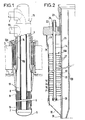
- Figure 1 shows in elevation with partial cutaway the heat exchanger between the sodium-primary and secondary circuits.
- FIG. 2 shows the detail of a device for reducing thermal stresses with an internal shell and metal plates in a ring.
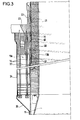
- FIG. 3 shows the detail of a device for reducing thermal stresses comprising a gas circulation coil in contact with the ferrule and an insulation between it and an internal ferrule.
- the bath 1 of liquid sodium in the reactor vessel is surmounted by the protective concrete slab 2.
- the arrival of the secondary liquid sodium takes place in the head 15 of the exchanger through the pipe 3, which extends inside the exchanger by the internal ferrule 4.
- the bottom 5 of the exchanger is surmounted by an annular tubular bundle 6 with lower 7 and upper tubular plates 8.
- the primary sodium penetrates around the tubes of the tubular bundle through opening 9 and spring cooled by the opening 10.
- the upper tubular plate 8 is surmounted by an annular duct 11 for discharging the heated secondary sodium, which leaves the exchanger by the duct 12.
- the entire device for reducing stresses around the periphery of the exchanger is shown in 13A and 13B, with its suspension tubes such as 14.
- the shell 21 of the exchanger is connected via a thin skirt 23 to a flange 22 resting on the protective concrete slab, not shown.
- the ferrule 21 is surrounded by a thin jacket 24, inside which is arranged the device 13A tending to reduce the convection currents of hot argon.
- the tubes 14 carrying spacer rings not shown to support the plates 27 are hooked by supports 25 to the flange 22, and provided at their lower end with plugs 26 for supporting columns of metal plates 27 in a ring, staggered vertically at constant spacing.
- These plates are spaced from the periphery of the ferrule 21 by a play of a few millimeters, and at regular intervals, some of the metal plates 32 are provided on their internal edge with a metallic seal 33 so as to reduce circulation as much as possible.
- argon from bottom to top along the outer wall of the outer shell 21.
- the plates are further divided in the direction of the height into groups each comprising a common outer shell such as 34, spaced a few millimeters from the outer jacket 24. Between two groups, an intermediate plate such as 35 is provided on its outer edge with a metallic seal 36.
- the tubes 14 can be used for the passage of control members of the nuclear reactor.
- the flange 22 has a lip (not sealed) 28 at the end 29, to a large extent reducing the circulation of argon from the inside of the envelope 24 to the outside.
- the jacket 24 is connected by a frustoconical surface 30 to an envelope 24 is connected by a frustoconical surface 30 to an envelope 31 very close to the ferrule 21, and forming a baffle on the path of the argon in the vicinity of the surface of liquid sodium.
- the plates 27 provide a heat-insulating function of the shell of the exchanger by attenuating the radiation and by maintaining an almost stationary argon zone in the vicinity of the shell of the exchanger; they also provide by circumferential conduction and by mutual radiation an effect of circumferential homogenization of the temperature of the shell 21 of the exchanger. This circumferential homogenization is also ensured by the radiation effect of the shell 13B which is at the temperature of the secondary sodium leaving the exchanger. Between the outer shell 21 to be protected and the inner shell 13B is an atmosphere of neutral gas, for example argon, which creates a relatively insulating layer with respect to heat transfer by conduction.
- the plates 27 also play the role of biological protection against radiation radiation from the active primary argon blanket, by the large number of screens that they interpose on the vertical path of this radiation along the ferrule.
- a coil 37 for circulating a heat exchange gas such as air.
- This coil delimited by an envelope 39 of heat insulation and ribs 40, is separated from the internal shell 13B by a layer 38 of heat insulation already reducing to a large extent the heat transmission of the heated secondary sodium to the external shell.
- the gas circulation coil and the insulation cooperate with the plate crowns to ensure the temperature uniformity of the outer shell.
- the invention can be applied, apart from exchangers of the kind described in the examples, to other devices passing through the slab surmounting the bath of liquid alkali metal, such as primary pumps or integrated purification devices.
Landscapes
- Engineering & Computer Science (AREA)
- Physics & Mathematics (AREA)
- Health & Medical Sciences (AREA)
- Life Sciences & Earth Sciences (AREA)
- Biomedical Technology (AREA)
- General Health & Medical Sciences (AREA)
- Molecular Biology (AREA)
- Plasma & Fusion (AREA)
- General Engineering & Computer Science (AREA)
- High Energy & Nuclear Physics (AREA)
- Heat-Exchange Devices With Radiators And Conduit Assemblies (AREA)
- Monitoring And Testing Of Nuclear Reactors (AREA)
Applications Claiming Priority (2)
| Application Number | Priority Date | Filing Date | Title |
|---|---|---|---|
| FR8014841A FR2486298A1 (fr) | 1980-07-03 | 1980-07-03 | Dispositif de reduction des contraintes thermiques sur la virole d'un appareil baignant dans le bain de metal alcalin liquide d'un reacteur nucleaire a neutrons rapides |
| FR8014841 | 1980-07-03 |
Publications (2)
| Publication Number | Publication Date |
|---|---|
| EP0043766A1 EP0043766A1 (fr) | 1982-01-13 |
| EP0043766B1 true EP0043766B1 (fr) | 1984-11-07 |
Family
ID=9243810
Family Applications (1)
| Application Number | Title | Priority Date | Filing Date |
|---|---|---|---|
| EP81401061A Expired EP0043766B1 (fr) | 1980-07-03 | 1981-07-01 | Dispositif de réduction des contraintes thermiques sur la virole d'un appareil baignant dans le bain de métal alcalin liquide d'un réacteur nucléaire à neutrons rapides |
Country Status (3)
| Country | Link |
|---|---|
| EP (1) | EP0043766B1 (enExample) |
| DE (1) | DE3167063D1 (enExample) |
| FR (1) | FR2486298A1 (enExample) |
Families Citing this family (2)
| Publication number | Priority date | Publication date | Assignee | Title |
|---|---|---|---|---|
| FR2524686A1 (fr) * | 1982-04-02 | 1983-10-07 | Novatome | Dispositif de protection contre la chaleur et les radiations pour un echangeur de chaleur intermediaire plongeant dans une cuve de reacteur nucleaire |
| CN101174482B (zh) * | 2007-12-11 | 2010-12-22 | 中国原子能科学研究院 | 钠-空气热交换器 |
Family Cites Families (7)
| Publication number | Priority date | Publication date | Assignee | Title |
|---|---|---|---|---|
| US1714948A (en) * | 1928-06-25 | 1929-05-28 | Gen Electric | Conduit for conveying high-temperature fluids |
| US3089520A (en) * | 1959-04-07 | 1963-05-14 | Huet Andre | Metallic piping system for fluids at high temperature |
| FR2036828A1 (en) * | 1969-04-04 | 1970-12-31 | Commissariat Energie Atomique | Integrated nuclear reactors |
| FR2283518A1 (fr) * | 1974-08-30 | 1976-03-26 | Commissariat Energie Atomique | Dispositif de protection thermique pour attente de cuve de reacteur nucleaire a neutrons rapides |
| FR2289033A1 (fr) * | 1974-09-06 | 1976-05-21 | Commissariat Energie Atomique | Dispositif de calorifugeage de surfaces horizontales de fermeture pour reacteur nucleaire refroidi par metal liquide |
| FR2316704A1 (fr) * | 1975-06-20 | 1977-01-28 | Atomic Energy Authority Uk | Reacteur nucleaire refroidi par un metal liquide |
| FR2422228A1 (fr) * | 1978-04-07 | 1979-11-02 | Commissariat Energie Atomique | Perfectionnement aux structures de calorifugeage de surfaces dans un reacteur nucleaire, notamment du genre a neutrons rapides |
-
1980
- 1980-07-03 FR FR8014841A patent/FR2486298A1/fr active Granted
-
1981
- 1981-07-01 DE DE8181401061T patent/DE3167063D1/de not_active Expired
- 1981-07-01 EP EP81401061A patent/EP0043766B1/fr not_active Expired
Also Published As
| Publication number | Publication date |
|---|---|
| DE3167063D1 (en) | 1984-12-13 |
| EP0043766A1 (fr) | 1982-01-13 |
| FR2486298B1 (enExample) | 1983-09-30 |
| FR2486298A1 (fr) | 1982-01-08 |
Similar Documents
| Publication | Publication Date | Title |
|---|---|---|
| FR2723798A1 (fr) | Reacteur nucleaire refroidi par metal liquide comprenant un systeme de refroidissement perfectionne, ce systeme et un procede utilisant ce systeme. | |
| EP0344041A1 (fr) | Réacteur nucléaire à dispositif d'injection d'eau de refroidissement de secours | |
| US4224983A (en) | Heat exchange apparatus for a reactor | |
| JPH07318678A (ja) | 液体金属冷却原子炉 | |
| EP0043766B1 (fr) | Dispositif de réduction des contraintes thermiques sur la virole d'un appareil baignant dans le bain de métal alcalin liquide d'un réacteur nucléaire à neutrons rapides | |
| JPS6153675B2 (enExample) | ||
| EP0163564B1 (fr) | Reacteur nucléaire à neutrons rapides à générateur de vapeur intégré dans la cuve | |
| JPS5814639B2 (ja) | ゲンシロヨウダンネツソウチ | |
| EP0246486B1 (fr) | Echangeur de rechauffage d'air sous pression en contrecourant de fumées circulant dans des faisceaux tubulaires | |
| EP0064920B1 (fr) | Dispositif de production de vapeur et de prélèvement de chaleur dans un réacteur nucléaire à neutrons rapides | |
| EP0020264A1 (fr) | Echangeur de chaleur du type semi-modulaire pour réacteur nucléaire | |
| US4357297A (en) | Apparatus for thermally insulating nuclear reactor primary vessels | |
| US4081322A (en) | Device for thermal insulation of a prestressed concrete vessel which affords resistance to the pressure of a vaporizable fluid contained in said vessel | |
| EP0041452B1 (fr) | Dispositif de réduction des contraintes thermiques sur un échangeur de chaleur | |
| EP0090743B1 (fr) | Dispositif de protection contre la chaleur et les radiations pour un échangeur de chaleur intermédiaire plongeant dans une cuve de réacteur nucléaire | |
| JP2986348B2 (ja) | 上鏡蓋型原子炉容器 | |
| US4676947A (en) | Device for thermal protection of a component of a fast-neutron nuclear reactor | |
| FR2491248A1 (fr) | Dispositif de calorifugeage pour isoler la region superieure de l'espace annulaire separant les cuves principales et de securite d'un reacteur nucleaire a neutrons rapides | |
| JP2725804B2 (ja) | 原子炉容器 | |
| EP0039290B1 (fr) | Dispositif de réduction des contraintes thermiques dans le fond d'un échangeur de chaleur vertical | |
| US5013521A (en) | Internal shell of a fast-neutron nuclear reactor comprising a thermal protection device | |
| US3151035A (en) | Nuclear reactor fuel elements | |
| JPS6313518Y2 (enExample) | ||
| EP0119915A1 (fr) | Réacteur nucléaire à neutrons rapides de type intégré | |
| JPS6331078B2 (enExample) |
Legal Events
| Date | Code | Title | Description |
|---|---|---|---|
| PUAI | Public reference made under article 153(3) epc to a published international application that has entered the european phase |
Free format text: ORIGINAL CODE: 0009012 |
|
| AK | Designated contracting states |
Designated state(s): BE DE FR GB IT NL |
|
| 17P | Request for examination filed |
Effective date: 19820618 |
|
| ITF | It: translation for a ep patent filed | ||
| GRAA | (expected) grant |
Free format text: ORIGINAL CODE: 0009210 |
|
| RAP1 | Party data changed (applicant data changed or rights of an application transferred) |
Owner name: STEIN INDUSTRIE SOCIETE ANONYME DITE: |
|
| AK | Designated contracting states |
Designated state(s): BE DE FR GB IT NL |
|
| REF | Corresponds to: |
Ref document number: 3167063 Country of ref document: DE Date of ref document: 19841213 |
|
| PLBE | No opposition filed within time limit |
Free format text: ORIGINAL CODE: 0009261 |
|
| STAA | Information on the status of an ep patent application or granted ep patent |
Free format text: STATUS: NO OPPOSITION FILED WITHIN TIME LIMIT |
|
| 26N | No opposition filed | ||
| PGFP | Annual fee paid to national office [announced via postgrant information from national office to epo] |
Ref country code: NL Payment date: 19870731 Year of fee payment: 7 |
|
| PG25 | Lapsed in a contracting state [announced via postgrant information from national office to epo] |
Ref country code: GB Effective date: 19880701 |
|
| PG25 | Lapsed in a contracting state [announced via postgrant information from national office to epo] |
Ref country code: BE Effective date: 19880731 |
|
| REG | Reference to a national code |
Ref country code: FR Ref legal event code: TP |
|
| BERE | Be: lapsed |
Owner name: STEIN INDUSTRIE Effective date: 19880731 |
|
| PG25 | Lapsed in a contracting state [announced via postgrant information from national office to epo] |
Ref country code: NL Effective date: 19890201 |
|
| GBPC | Gb: european patent ceased through non-payment of renewal fee | ||
| NLV4 | Nl: lapsed or anulled due to non-payment of the annual fee | ||
| PG25 | Lapsed in a contracting state [announced via postgrant information from national office to epo] |
Ref country code: DE Effective date: 19890401 |
|
| PGFP | Annual fee paid to national office [announced via postgrant information from national office to epo] |
Ref country code: FR Payment date: 19910716 Year of fee payment: 11 |
|
| PG25 | Lapsed in a contracting state [announced via postgrant information from national office to epo] |
Ref country code: FR Effective date: 19930331 |
|
| REG | Reference to a national code |
Ref country code: FR Ref legal event code: ST |