EP0043760A1 - Dampftrockneranlage für Dampferzeuger, insbesondere für Kernreaktor-Dampferzeuger - Google Patents
Dampftrockneranlage für Dampferzeuger, insbesondere für Kernreaktor-Dampferzeuger Download PDFInfo
- Publication number
- EP0043760A1 EP0043760A1 EP81401048A EP81401048A EP0043760A1 EP 0043760 A1 EP0043760 A1 EP 0043760A1 EP 81401048 A EP81401048 A EP 81401048A EP 81401048 A EP81401048 A EP 81401048A EP 0043760 A1 EP0043760 A1 EP 0043760A1
- Authority
- EP
- European Patent Office
- Prior art keywords
- drying
- elements
- steam
- series
- assembly according
- Prior art date
- Legal status (The legal status is an assumption and is not a legal conclusion. Google has not performed a legal analysis and makes no representation as to the accuracy of the status listed.)
- Granted
Links
Images


Classifications
-
- F—MECHANICAL ENGINEERING; LIGHTING; HEATING; WEAPONS; BLASTING
- F22—STEAM GENERATION
- F22B—METHODS OF STEAM GENERATION; STEAM BOILERS
- F22B37/00—Component parts or details of steam boilers
- F22B37/02—Component parts or details of steam boilers applicable to more than one kind or type of steam boiler
- F22B37/26—Steam-separating arrangements
- F22B37/28—Steam-separating arrangements involving reversal of direction of flow
- F22B37/286—Steam-separating arrangements involving reversal of direction of flow specially adapted for steam generators of nuclear power plants
Definitions
- the present invention relates to a drying assembly for water-vapor separation equipment located in the upper part of a steam generator with natural circulation, that is to say downstream of the production of steam.
- Lt 2 drying assembly according to the invention is intended in particular to ensure the separation of steam in a steam generator associated with a nuclear reactor, although this application is in no way limiting.
- steam generators with natural circulation include water-steam separation equipment so that the steam produced by the tube bundle (or by combustible elements in the case of boiling water reactors) is as dry as possible at the outlet. of the generator.
- separation equipment comprises two assemblies arranged in series in the direction of flow of the vapor, these assemblies being distinguished essentially by the amount of water that they can capture; a first set, or set of primary separators, is intended to remove most of the water to be separated from the vapor, while the second set, or drying set, makes it possible to capture the few particles of water which can still be entrained by steam downstream of the set of primary separators.
- Drying devices are already known which make it possible to finely dry the steam coming from the primary separators, in particular by the French patent published under the number 2.275.731.
- This document describes a separation equipment in which the drying assembly (called in the patent second moisture separator) consists of two groups of chevron separators arranged one above the other, the inlet of the steam to be dried is made by the periphery and its exit by the central zone.
- French utility certificate published under No. 2.254.092 describes a set of separators formed by drying frames constituting either a bed of several concentric rings or a radiating structure, an arrangement of pipes being provided at the base of the frames for collecting and draining the collected water. Such arrangements are suitable for boiling water reactors.
- the present invention proposes a new design of a drying assembly which eliminates these drawbacks by allowing, on the one hand a modular construction and by ensuring on the other hand a large available exchange surface in a global volume as small as possible.
- the drying assembly according to the invention therefore makes it possible to achieve a gain in volume at the level of the generator pressure envelope, which makes it possible to more closely adapt its design to the conditions of optimal termo-hydraulic operation. It also ensures a distribution and organization of the steam circulation which promotes a particularly efficient use of the section offered within the steam generator as well as the improvement of the operation and therefore of the separation efficiency.
- the drying assembly of the invention comprises a plurality of drying elements, steam guiding means organizing the admission of wet steam into the drying elements and the dry steam outlet from the drying elements and separate water collection devices associated with the drying elements.
- the drying assembly according to the invention is characterized in a characteristic way by the fact that it has a modular structure, all the drying elements being identical and distributed according to a symmetry of ternary revolution and in that, in a first series of drying elements, said elements are arranged radially and associated with steam guiding means which provide alternati around the axis of revolution, a volume of dry steam outlet from one element and a volume of wet steam intake into the next element, the intake volumes each occupying a lower cross section of the assembly an area identical to that occupied by each of the outlet volumes in an upper cross section of the assembly.
- the drying assembly of the invention may advantageously comprise one or more concentric series of identical drying elements arranged radially as has just been defined, and in addition one or more series of drying elements constituting an annular peripheral ring where the elements, of parallelepipedal shape and preferably identical to the drying elements which they surround, are arranged along the sides of a polygonal shape, each extending from the end of a radial element to the following radial element of the same series.
- the means for guiding the steam associated with the drying elements of the second series provide for each a volume of admittance situated radially outside the element, between the latter and a cylindrical enclosure, and on the other hand an outlet volume located radially inside the element, whereas for the drying elements of the.
- each element of the second series forms with two elements of the first series a cell of triangular shape whose three sides are constituted respectively by the three drying elements.
- each cell is advantageously divided by a partition isolating the drying elements from each other and comprising three vertical plates extending in a part of each of the bisector planes of the cell and fixed to each other along a contact axis in the center of the cell, so as to delimit there three equal compartments, and on the other hand three transverse plates comprising two lower plates closing the base two compartments respectively and an upper plate closing the top of the third compartment.
- the best operating conditions are generally obtained when the cells are arranged in the drying assembly so that the drying element adjacent to one of the compartments closed by a lower plate constitutes an element of the peripheral crown.
- the drying assembly is limited by drying elements defining a hexagon.
- identical hexagons can be combined to occupy a larger overall cross-section.
- the drying assembly comprises water collection devices opening out into conduits oriented parallel to the axis of symmetry arranged at the outer radial end of each of the elements of the first series, said conduits serving also for collecting separate water in the drying elements of the second series, and the guide means comprise an annular plate delimiting a volume of admission of wet steam into the drying elements of the peripheral ring and extending between a cylindrical outer enclosure and the top of each of the elements of the second series.
- FIG. 1 the outer casing of a steam generator is shown schematically at 1, the dome-shaped top of which has an orifice 2 for the outlet of the steam produced.
- the steam production chamber housed in the lower part of the casing 1 and in which is installed the traditional bundle of tubes (not shown) in which a primary fluid circulates and which ensures the vaporization of the secondary fluid (namely water) contained in the chamber 3.
- the vapor s' escapes from the chamber 3 by passing through a water-vapor separator 4 of conventional structure and ensuring the collection of most of the water entrained by the vapor as well as its return to the chamber.
- the drying assembly 6 may also contain fine droplets of water in suspension, droplets of which the drying assembly according to the invention, generally designated in 6, ensures collection and return by pipes E to the lower part of the generator.
- the drying assembly 6 is, for this purpose, located downstream of the separator 4 and the steam 8 leaving this assembly 6 has a humidity compatible with the proper functioning of the devices using this steam. It will be noted that the volume of the generator located / downstream of the drying assembly is isolated from the rest of the generator by a separator plate generally designated at 7 and whose structure which will be described in detail below is such that it forces the "wet" steam to pass through the drying assembly 6 before reaching the discharge orifice 2, which is located above the drying assembly, substantially on its axis.
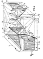
- the drying assembly consists of drying elements 9a and 9b of parallelepiped shape and all identical, associated with partitions which guide the steam circulating vertically, from bottom to top, through the drying elements.
- the latter are distributed in a symmetry of ternary revolution around the axis of the assembly, so as to form a modular structure with six modules in the particular case shown.
- the elements 9a six in number in the example considered, are arranged radially so as to form a radiating star centered on the axis of the enclosure.
- the second series constitutes a peripheral ring-shaped ring around the first.
- the drying elements 9b are arranged there, vertically like the first, each on one side of a polygonal section, here hexagonal, and extending between one end of a radial element and the end of the following radial element.
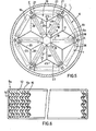
- the drying elements have a conventional structure such as that which is shown in FIG. 6 by way of example, constituted by a rectangular peripheral frame 10 with a U-section open at 11 and 12 on its two large opposite faces and filled with a stack. strips or rafters 15 forming chicane passages 15a allowing the frame to pass through with steam. These strips are arranged vertically so that the water droplets which deposit on them can slide towards the base of the frame 9 in which is formed a drainage channel 14 situated under a perforated plate 13 supporting the strips 15.
- the separator plate 7 has been shown in dashed lines in FIG. 5. It comprises an annular external part 16 to which the drying elements 9b of the peripheral ring are fixed, this external part 16 closing the gaps located between the envelope 1 of form cylindrical and the dryers that occupy a rectangular section, each on one side of the polygon.
- the plate 7 also includes a central part 17, connected to the part 16 by radial members 18 advantageously extending along the length of the dryers 9a to which they are fixed; the central part 17 ensures the closure of the top of the central space left free between the ends of the dryers 9a.
- the attachment of the dryers to the plate 7 can optionally be supplemented by vertical frames B (see FIGS. 1 and 5) integral with the plate 7 and to which are fixed the faces of the dryers 9a by which the dry steam exits the dryers to gain the space located above the plate 7 as will be explained later.
- each dryer 9b constitutes with two consecutive radial dryers 9a, a cell generally designated in 19 ( Figure 5), and having a general shape of equilateral triangle.
- each cell 19 is divided by a partition whose role is to achieve the isolation of each dryer 9a or 9b from the others.
- This partitioning comprises three vertical plates 20, 21 and 22, which extend respectively from the center of the cell along each of the bisectors of the angles at the top of the cell, these plates being secured according to their common contact line H (FIG. 5 ) and delimiting three equal compartments in the cell; the partitioning is completed by two lower rectangular plates 23 and 24 and an upper triangular plate 25.
- the lower plate 23 closes the lower base of the compartment adjacent to the peripheral dryer 9b and it is linked to the lower edge S thereof and to the lower edges of the vertical plates 20 and 22, while the lower plate 24 closes off the same way a compartment adjacent to one of the radial dryers 9a by being linked to the lower edge thereof and to the lower edges of the vertical plates 20 and 21 (see Figure 3).
- the upper triangular plate 25, in turn, closes the upper part of the third compartment of the cell and it is linked to the upper edge R of the second radial dryer 9a and to the upper edges of the vertical plates 21 and 22. (FIG. 3).
- the steam can have free access to the radial dryers 9a through the intake compartments delimited by the vertical plates 21 and 22 and closed at their tops by the upper plates 25.
- the vapor is therefore forced to pass through the dryers 9a according to the arrows F 3 (FIG. 4) and it exits therefrom through the outlet compartments delimited by the vertical plates 20 and 21 closed at their base by the plate 24 but open at their upper part to allow the steam to rise according to the arrow F 4 in the direction of the discharge orifice 2.
- the lower plates 23 and upper 25 will be slightly inclined in order to facilitate the guiding of the vapor.
- the contact axis of the three vertical plates of the partitioning, in H, then extends only over part of the height of the cell, in its middle part.
- FIG. 4 thus shows a collecting duct E collecting the separated water in a radial drying element and two adjacent peripheral drying elements, therefore belonging to two different cells of the modular construction.
Landscapes
- Engineering & Computer Science (AREA)
- Physics & Mathematics (AREA)
- Thermal Sciences (AREA)
- Mechanical Engineering (AREA)
- General Engineering & Computer Science (AREA)
- Drying Of Solid Materials (AREA)
- Beans For Foods Or Fodder (AREA)
- Treatment And Processing Of Natural Fur Or Leather (AREA)
Priority Applications (1)
| Application Number | Priority Date | Filing Date | Title |
|---|---|---|---|
| AT81401048T ATE5495T1 (de) | 1980-07-02 | 1981-06-30 | Dampftrockneranlage fuer dampferzeuger, insbesondere fuer kernreaktor-dampferzeuger. |
Applications Claiming Priority (2)
| Application Number | Priority Date | Filing Date | Title |
|---|---|---|---|
| FR8014744A FR2486201A1 (fr) | 1980-07-02 | 1980-07-02 | Ensemble de sechage pour generateur de vapeur, destine notamment aux generateurs de vapeur de reacteurs nucleaires |
| FR8014744 | 1980-07-02 |
Publications (2)
| Publication Number | Publication Date |
|---|---|
| EP0043760A1 true EP0043760A1 (de) | 1982-01-13 |
| EP0043760B1 EP0043760B1 (de) | 1983-11-30 |
Family
ID=9243772
Family Applications (1)
| Application Number | Title | Priority Date | Filing Date |
|---|---|---|---|
| EP81401048A Expired EP0043760B1 (de) | 1980-07-02 | 1981-06-30 | Dampftrockneranlage für Dampferzeuger, insbesondere für Kernreaktor-Dampferzeuger |
Country Status (14)
| Country | Link |
|---|---|
| US (1) | US4383500A (de) |
| EP (1) | EP0043760B1 (de) |
| JP (1) | JPS5743101A (de) |
| AT (1) | ATE5495T1 (de) |
| BR (1) | BR8103932A (de) |
| CA (1) | CA1184323A (de) |
| DE (1) | DE3161550D1 (de) |
| EG (1) | EG14991A (de) |
| ES (1) | ES503588A0 (de) |
| FR (1) | FR2486201A1 (de) |
| GR (1) | GR75715B (de) |
| PT (1) | PT73266B (de) |
| YU (1) | YU41458B (de) |
| ZA (1) | ZA813847B (de) |
Cited By (2)
| Publication number | Priority date | Publication date | Assignee | Title |
|---|---|---|---|---|
| WO2009015949A1 (de) | 2007-07-27 | 2009-02-05 | Siemens Aktiengesellschaft | Abscheider |
| DE102009055932B4 (de) * | 2009-11-27 | 2015-10-15 | Munters Euroform Gmbh | Windkraftrad |
Families Citing this family (5)
| Publication number | Priority date | Publication date | Assignee | Title |
|---|---|---|---|---|
| DE3301688C2 (de) * | 1983-01-20 | 1985-04-18 | Gottfried Bischoff Bau kompl. Gasreinigungs- und Wasserrückkühlanlagen GmbH & Co KG, 4300 Essen | Waschturm für eine Anlage zur Entschwefelung von Rauchgas |
| US4902317A (en) * | 1987-09-05 | 1990-02-20 | Paul Gutermuth | Purifying apparatus for gaseous fluids |
| DE102005056543B4 (de) * | 2005-11-28 | 2016-01-14 | Rea Plastik Tech Gmbh | Tropfenabscheider für einen Gaswäscher |
| US7686862B1 (en) * | 2008-09-22 | 2010-03-30 | Peerless Mfg. Co. | Composite vane and method of manufacture |
| JP5470099B2 (ja) * | 2010-03-05 | 2014-04-16 | 日立Geニュークリア・エナジー株式会社 | 沸騰水型原子力プラントおよび蒸気乾燥器 |
Citations (4)
| Publication number | Priority date | Publication date | Assignee | Title |
|---|---|---|---|---|
| FR1549351A (de) * | 1966-09-28 | 1968-12-13 | ||
| DE2104355A1 (de) * | 1970-02-02 | 1971-10-21 | Westinghouse Electric Corp | Vorrichtung zur Abscheidung von Wasser oder anderen Beladungen strömender Dämpfe und Gase |
| FR2310793A1 (fr) * | 1975-05-13 | 1976-12-10 | Nikolaevich Artemov | Perfectionnements apportes aux separateurs verticaux |
| DE2819346A1 (de) * | 1977-05-16 | 1978-11-23 | Asea Atom Ab | Siedereaktor |
Family Cites Families (7)
| Publication number | Priority date | Publication date | Assignee | Title |
|---|---|---|---|---|
| US1992824A (en) * | 1933-12-30 | 1935-02-26 | Gen Electric | Mercury boiler |
| US3370574A (en) * | 1966-11-04 | 1968-02-27 | Superior Comb Ind Inc | Steam generating apparatus |
| CH475023A (de) * | 1967-05-31 | 1969-07-15 | Sulzer Ag | Wasserabscheider zu einem Sattdampferzeuger, insbesondere für Atomkernreaktoranlagen |
| US3735569A (en) * | 1971-09-07 | 1973-05-29 | Combustion Eng | Water-steam separator |
| FR2196702A5 (de) * | 1972-08-21 | 1974-03-15 | Babcock Atlantique Sa | |
| US3866067A (en) * | 1973-05-21 | 1975-02-11 | Fairchild Camera Instr Co | Charge coupled device with exposure and antiblooming control |
| US3850599A (en) * | 1973-09-24 | 1974-11-26 | Combustion Eng | Means for separating entrained liquid |
-
1980
- 1980-07-02 FR FR8014744A patent/FR2486201A1/fr active Granted
-
1981
- 1981-06-04 GR GR65154A patent/GR75715B/el unknown
- 1981-06-09 ZA ZA00813847A patent/ZA813847B/xx unknown
- 1981-06-10 US US06/272,443 patent/US4383500A/en not_active Expired - Lifetime
- 1981-06-23 BR BR8103932A patent/BR8103932A/pt not_active IP Right Cessation
- 1981-06-25 YU YU1582/81A patent/YU41458B/xx unknown
- 1981-06-26 PT PT73266A patent/PT73266B/pt not_active IP Right Cessation
- 1981-06-30 CA CA000380927A patent/CA1184323A/fr not_active Expired
- 1981-06-30 AT AT81401048T patent/ATE5495T1/de active
- 1981-06-30 DE DE8181401048T patent/DE3161550D1/de not_active Expired
- 1981-06-30 EP EP81401048A patent/EP0043760B1/de not_active Expired
- 1981-07-01 EG EG375/81A patent/EG14991A/xx active
- 1981-07-01 ES ES503588A patent/ES503588A0/es active Granted
- 1981-07-02 JP JP56103894A patent/JPS5743101A/ja active Granted
Patent Citations (4)
| Publication number | Priority date | Publication date | Assignee | Title |
|---|---|---|---|---|
| FR1549351A (de) * | 1966-09-28 | 1968-12-13 | ||
| DE2104355A1 (de) * | 1970-02-02 | 1971-10-21 | Westinghouse Electric Corp | Vorrichtung zur Abscheidung von Wasser oder anderen Beladungen strömender Dämpfe und Gase |
| FR2310793A1 (fr) * | 1975-05-13 | 1976-12-10 | Nikolaevich Artemov | Perfectionnements apportes aux separateurs verticaux |
| DE2819346A1 (de) * | 1977-05-16 | 1978-11-23 | Asea Atom Ab | Siedereaktor |
Cited By (4)
| Publication number | Priority date | Publication date | Assignee | Title |
|---|---|---|---|---|
| WO2009015949A1 (de) | 2007-07-27 | 2009-02-05 | Siemens Aktiengesellschaft | Abscheider |
| EP2025385A1 (de) * | 2007-07-27 | 2009-02-18 | Siemens Aktiengesellschaft | Abscheider |
| US8343246B2 (en) | 2007-07-27 | 2013-01-01 | Siemens Aktiengesellschaft | Separator |
| DE102009055932B4 (de) * | 2009-11-27 | 2015-10-15 | Munters Euroform Gmbh | Windkraftrad |
Also Published As
| Publication number | Publication date |
|---|---|
| ZA813847B (en) | 1982-07-28 |
| FR2486201A1 (fr) | 1982-01-08 |
| JPH037841B2 (de) | 1991-02-04 |
| GR75715B (de) | 1984-08-02 |
| US4383500A (en) | 1983-05-17 |
| EP0043760B1 (de) | 1983-11-30 |
| PT73266B (fr) | 1982-07-01 |
| JPS5743101A (en) | 1982-03-11 |
| ES8204831A1 (es) | 1982-05-16 |
| BR8103932A (pt) | 1982-03-09 |
| CA1184323A (fr) | 1985-03-19 |
| YU158281A (en) | 1984-02-29 |
| FR2486201B1 (de) | 1984-12-28 |
| ATE5495T1 (de) | 1983-12-15 |
| EG14991A (en) | 1985-12-31 |
| ES503588A0 (es) | 1982-05-16 |
| YU41458B (en) | 1987-06-30 |
| PT73266A (fr) | 1981-07-01 |
| DE3161550D1 (en) | 1984-01-05 |
Similar Documents
| Publication | Publication Date | Title |
|---|---|---|
| EP0043760B1 (de) | Dampftrockneranlage für Dampferzeuger, insbesondere für Kernreaktor-Dampferzeuger | |
| CA2741243C (fr) | Dispositif de raclage pour installation de filtration sous pression | |
| EP0246151A1 (de) | Abscheider mit Flügelflächen zur Abscheidung von Flüssigkeitsteilchen | |
| FR2462655A1 (fr) | Distributeur collecteur de boues pour generateur nucleaire de vapeur | |
| EP0236647B1 (de) | Wirbelbettwärmeerzeuger mit Mitteln für Aschenbeseitigung und Wärmerückgewinnung | |
| EP0626536B1 (de) | Dampferzeuger ausgerüstet mit einem Fremdpartikelfilter | |
| CH622091A5 (de) | ||
| EP0032088B1 (de) | Vorrichtung zum Trennen von Flüssigkeit und Dampf aus einem Fluid-Strom und Dampferzeuger mit solchen Vorrichtungen | |
| FR2707733A1 (fr) | Générateur de vapeur à cyclones démontables. | |
| EP0607071B1 (de) | Wärmetauscher mit oben durch einen Überlauf gespeistes Sekundärfluid | |
| EP0010261A1 (de) | Vertikaler Wasserdampf-Abscheider-Überhitzer | |
| FR2924486A1 (fr) | Systeme double collecteur de boue et de corps etrangers pour generateur de vapeur | |
| EP0568434B1 (de) | Vorrichtung zur Abgabe und Verteilung von Speise- und Rezirkulationswasser in der Sekundärseite eines Dampferzeugers | |
| CA1162494A (fr) | Dispositif de separation d'eau et de vapeur a la sortie d'enceinte de vaporisation d'un generateur de vapeur | |
| EP0566477B1 (de) | Dampferzeuger mit einer Wasserablenkungvorrichtung und einer Schlammentleerungsbahn | |
| FR2581172A1 (fr) | Condensateurs de vapeurs a refroidissement par air | |
| EP0020264B1 (de) | Wärmetauscher des Teil-Modul-Typs für Kernreaktor | |
| EP0250319B1 (de) | Dampferzeuger mit verbesserten Trocknungsmitteln | |
| BE879140R (fr) | Separateur-surchauffeur de vapeur vertical | |
| EP0044004B1 (de) | Abscheidevorrichtung für in Gas oder in Dampf mitgerissene Flüssigkeitströpfchen | |
| FI75275B (fi) | Torkningsenhet foer en aonggenerator avsedd i synnerhet foer aonggeneratorer foer kaernreaktorer. | |
| CA1174185A (fr) | Dispositif separateur de gouttelettes de liquide entrainees dans un gaz ou une vapeur | |
| FR2851031A1 (fr) | Generateur de vapeur comportant un dispositif de fourniture d'eau d'alimentation realisant le piegeage de corps etrangers | |
| EP0557173A1 (de) | Dampferzeuger mit Speisewasserzuführungsleitung im niedrigen Teil | |
| FR2573992A1 (fr) | Perfectionnements aux evaporateurs a descendage |
Legal Events
| Date | Code | Title | Description |
|---|---|---|---|
| PUAI | Public reference made under article 153(3) epc to a published international application that has entered the european phase |
Free format text: ORIGINAL CODE: 0009012 |
|
| AK | Designated contracting states |
Designated state(s): AT BE CH DE FR GB IT NL SE |
|
| 17P | Request for examination filed |
Effective date: 19811204 |
|
| ITF | It: translation for a ep patent filed |
Owner name: JACOBACCI & PERANI S.P.A. |
|
| GRAA | (expected) grant |
Free format text: ORIGINAL CODE: 0009210 |
|
| AK | Designated contracting states |
Designated state(s): AT BE CH DE FR GB IT LI NL SE |
|
| REF | Corresponds to: |
Ref document number: 5495 Country of ref document: AT Date of ref document: 19831215 Kind code of ref document: T |
|
| REF | Corresponds to: |
Ref document number: 3161550 Country of ref document: DE Date of ref document: 19840105 |
|
| PLBE | No opposition filed within time limit |
Free format text: ORIGINAL CODE: 0009261 |
|
| STAA | Information on the status of an ep patent application or granted ep patent |
Free format text: STATUS: NO OPPOSITION FILED WITHIN TIME LIMIT |
|
| 26N | No opposition filed | ||
| ITTA | It: last paid annual fee | ||
| EAL | Se: european patent in force in sweden |
Ref document number: 81401048.4 |
|
| PGFP | Annual fee paid to national office [announced via postgrant information from national office to epo] |
Ref country code: SE Payment date: 19970528 Year of fee payment: 17 |
|
| PGFP | Annual fee paid to national office [announced via postgrant information from national office to epo] |
Ref country code: DE Payment date: 19970604 Year of fee payment: 17 |
|
| PGFP | Annual fee paid to national office [announced via postgrant information from national office to epo] |
Ref country code: CH Payment date: 19970610 Year of fee payment: 17 Ref country code: AT Payment date: 19970610 Year of fee payment: 17 |
|
| PGFP | Annual fee paid to national office [announced via postgrant information from national office to epo] |
Ref country code: GB Payment date: 19970623 Year of fee payment: 17 |
|
| PGFP | Annual fee paid to national office [announced via postgrant information from national office to epo] |
Ref country code: FR Payment date: 19970624 Year of fee payment: 17 |
|
| PGFP | Annual fee paid to national office [announced via postgrant information from national office to epo] |
Ref country code: NL Payment date: 19970630 Year of fee payment: 17 |
|
| PG25 | Lapsed in a contracting state [announced via postgrant information from national office to epo] |
Ref country code: LI Free format text: LAPSE BECAUSE OF NON-PAYMENT OF DUE FEES Effective date: 19980630 Ref country code: GB Free format text: LAPSE BECAUSE OF NON-PAYMENT OF DUE FEES Effective date: 19980630 Ref country code: CH Free format text: LAPSE BECAUSE OF NON-PAYMENT OF DUE FEES Effective date: 19980630 Ref country code: AT Free format text: LAPSE BECAUSE OF NON-PAYMENT OF DUE FEES Effective date: 19980630 |
|
| PG25 | Lapsed in a contracting state [announced via postgrant information from national office to epo] |
Ref country code: SE Free format text: LAPSE BECAUSE OF NON-PAYMENT OF DUE FEES Effective date: 19980701 |
|
| PG25 | Lapsed in a contracting state [announced via postgrant information from national office to epo] |
Ref country code: NL Free format text: LAPSE BECAUSE OF NON-PAYMENT OF DUE FEES Effective date: 19990101 |
|
| REG | Reference to a national code |
Ref country code: CH Ref legal event code: PL |
|
| GBPC | Gb: european patent ceased through non-payment of renewal fee |
Effective date: 19980630 |
|
| PG25 | Lapsed in a contracting state [announced via postgrant information from national office to epo] |
Ref country code: FR Free format text: LAPSE BECAUSE OF NON-PAYMENT OF DUE FEES Effective date: 19990226 |
|
| NLV4 | Nl: lapsed or anulled due to non-payment of the annual fee |
Effective date: 19990101 |
|
| EUG | Se: european patent has lapsed |
Ref document number: 81401048.4 |
|
| PG25 | Lapsed in a contracting state [announced via postgrant information from national office to epo] |
Ref country code: DE Free format text: LAPSE BECAUSE OF NON-PAYMENT OF DUE FEES Effective date: 19990401 |
|
| REG | Reference to a national code |
Ref country code: FR Ref legal event code: ST |
|
| PGFP | Annual fee paid to national office [announced via postgrant information from national office to epo] |
Ref country code: BE Payment date: 20000704 Year of fee payment: 20 |
|
| BE20 | Be: patent expired |
Free format text: 20010630 *FRAMATOME |