EP0043671A1 - Zeitmess-System - Google Patents
Zeitmess-System Download PDFInfo
- Publication number
- EP0043671A1 EP0043671A1 EP81302814A EP81302814A EP0043671A1 EP 0043671 A1 EP0043671 A1 EP 0043671A1 EP 81302814 A EP81302814 A EP 81302814A EP 81302814 A EP81302814 A EP 81302814A EP 0043671 A1 EP0043671 A1 EP 0043671A1
- Authority
- EP
- European Patent Office
- Prior art keywords
- buoys
- coil
- magnet
- course
- vehicle
- Prior art date
- Legal status (The legal status is an assumption and is not a legal conclusion. Google has not performed a legal analysis and makes no representation as to the accuracy of the status listed.)
- Withdrawn
Links
- 230000004044 response Effects 0.000 claims abstract description 10
- XLYOFNOQVPJJNP-UHFFFAOYSA-N water Substances O XLYOFNOQVPJJNP-UHFFFAOYSA-N 0.000 claims description 15
- 239000000463 material Substances 0.000 claims description 3
- 238000001514 detection method Methods 0.000 abstract description 4
- 239000003550 marker Substances 0.000 abstract description 2
- 230000000694 effects Effects 0.000 description 5
- 229910000859 α-Fe Inorganic materials 0.000 description 3
- 208000027418 Wounds and injury Diseases 0.000 description 2
- 238000000034 method Methods 0.000 description 2
- 230000004048 modification Effects 0.000 description 2
- 238000012986 modification Methods 0.000 description 2
- 230000035945 sensitivity Effects 0.000 description 2
- 230000001960 triggered effect Effects 0.000 description 2
- 230000004323 axial length Effects 0.000 description 1
- 238000010276 construction Methods 0.000 description 1
- 238000012937 correction Methods 0.000 description 1
- 230000006378 damage Effects 0.000 description 1
- 230000001419 dependent effect Effects 0.000 description 1
- 238000010586 diagram Methods 0.000 description 1
- 238000001914 filtration Methods 0.000 description 1
- 239000000383 hazardous chemical Substances 0.000 description 1
- 208000014674 injury Diseases 0.000 description 1
- 230000009191 jumping Effects 0.000 description 1
- 238000000465 moulding Methods 0.000 description 1
- 230000035699 permeability Effects 0.000 description 1
- 229920003023 plastic Polymers 0.000 description 1
- 239000004033 plastic Substances 0.000 description 1
- 230000011514 reflex Effects 0.000 description 1
- 230000001052 transient effect Effects 0.000 description 1
Images

Classifications
-
- G—PHYSICS
- G01—MEASURING; TESTING
- G01P—MEASURING LINEAR OR ANGULAR SPEED, ACCELERATION, DECELERATION, OR SHOCK; INDICATING PRESENCE, ABSENCE, OR DIRECTION, OF MOVEMENT
- G01P3/00—Measuring linear or angular speed; Measuring differences of linear or angular speeds
- G01P3/64—Devices characterised by the determination of the time taken to traverse a fixed distance
- G01P3/66—Devices characterised by the determination of the time taken to traverse a fixed distance using electric or magnetic means
-
- G—PHYSICS
- G07—CHECKING-DEVICES
- G07C—TIME OR ATTENDANCE REGISTERS; REGISTERING OR INDICATING THE WORKING OF MACHINES; GENERATING RANDOM NUMBERS; VOTING OR LOTTERY APPARATUS; ARRANGEMENTS, SYSTEMS OR APPARATUS FOR CHECKING NOT PROVIDED FOR ELSEWHERE
- G07C1/00—Registering, indicating or recording the time of events or elapsed time, e.g. time-recorders for work people
- G07C1/22—Registering, indicating or recording the time of events or elapsed time, e.g. time-recorders for work people in connection with sports or games
- G07C1/24—Race time-recorders
Definitions
- This invention relates to a system for providing on-board timing for a vehicle traversing a predetermined course.
- the invention is applicable for example to sports such as water skiing and allied water sports where an on-board measure of boat speed is required, and also motorcar and motorcycle racing where there is a requirement for lap times and speeds to be conveyed to the drivers.
- the rules require the boat speed to be maintained within certain limits for the run to be valid. For example, in the slalom event the boat traverses a course defined by successive pairs of buoys, the boat being driven between the buoys of each pair whilst the skier executes a prescribed slalom course. To ensure that each competitor receives the same advantage, the boat is driven at a certain prescribed speed, for example 36 m.p.h., and stop watch timing has been used in the past to ensure that the average boat speed over the course does not deviate from the prescribed spped by more than a specified amount, e.g. plus or minus 0.2 m.p.h.
- a specified amount e.g. plus or minus 0.2 m.p.h.
- the stop watch-timed period is made by an on-board official using buoys at the beginning and end of the course as reference points. Hitherto this has been considered unsatisfactory as the accuracy of timing is dependent on the official's reflexes and may vary over the course of several runs. Also the average boat speed can only be checked after the boat has completed the course.
- the object of the present invention is to provide a system for producing on-board timing for vehicles such as boats used in water sports and racing cars and motorcyles.
- a system for on-board timing for a vehicle traversing a predetermined course comprising sensing coil means adapted to be carried by the vehicle for producing an electrical signal in response to sensing at least one magnet located at at least one predetermined position along said course, on-board timing means and on-board control means responsive to said sensing coil means for controlling operation of the timing means to provide a record of the time interval elapsing between successive or selected electrical signals produced by said sensing coil means.
- the record of the time interval may be direct in terms of the actual time elapsed and/or indirect - for example in terms of the average speeds of the vehicle over the elapsed time interval.
- the distance between the positions at which said successive or selected signals are produced will be known and the average speed may be determined by dividing the known distance by the time interval elapsing between said signals.
- said course will be defined by a number of buoys at least one of which will have a magnet (preferably a permanent magnet) associated with it.
- the timing means preferably comprises two timers so that the buoys of the or each set may be used as entrance, exit and intermediate reference points, the arrangement being such that both timers are started as the boat passes the entrance buoy, one timer is stopped as the boat passes the intermediate buoy and the second timer is stopped as the boat passes the exit buoy.
- the second timer provides an indication of average boat speed over the full length of the course and the first timer provides an indication of average boat speed after part of the course has been traversed.
- This facility is particularly advantageous as it enables mid-course corrections to boat speed,to be made to ensure that the average speed over the complete course is within the specified range for the prescribed speed.
- the intermediate buoy may not be required and, in this case, only the second timer is necessary.
- each magnet is provided on the respective buoy in such a way that the magnetic field strength is substantially isotropic about a vertical axis when water borne.
- each magnet may create an anisotropic field, e.g. a bar magnet, and in this event special provision may be necessary to restrain the buoy against rotation when water borne, the arrangement being such that the dominant component of field strength is directed generally broadside on with respect to the direction of movement of the boat along the prescribed course.
- a feature of the invention in a narrower aspect thereof is the provision of means for discriminating between the magnetic fields of the buoy mounting magnets and the magnetic fields originating from other sources.
- a major source of extraneous magnetic fields will be the engine powering the boat and, in particular, the electrical ancillaries such as the ignition coil and alternator associated with the engine.
- the electrical ancillaries such as the ignition coil and alternator associated with the engine.
- discrimination is achieved by employing a magnetic sensor having directional properties and orienting the sensor so as to minimise the influence of magnetic fields originating from the engine and maximise the influence of magnetic fields originating from the buoy mounted magnets.
- the senor includes an electrical coil in which an EMF is induced by the buoy mounted magnets as the boat moves past the buoys.
- the desired sensor directional property can be achieved by using an elongated coil and arranging it broadside on relative to the boat.
- the coil is provided with a core of high magnetic permeability material and the core is arranged to project beyond at least one and preferably both ends of the coil.
- the coil surprisingly shows a marked sensitivity in the axial direction and the coil and core are therefore disposed broadside on with respect to the boat and hence endwise on with respect to the magnets whose polar axes will be disposed substantially vertically.
- the core may comprise a single ferrite rod or two or more ferrite rods located alongside each other and preferably the core extends beyond the coil by an amount corresponding to at least 100% of the axial length of the coil and in general it would appear that the greater the projection of the core from the coil the more pronounced the directional effect; however, it will be appreciated that there will be a lower limit on how short the coil can be made if a reasonably strong induced signal is to be obtained.
- the present invention contemplates the use of a permanent magnet/magnetic sensor arrangement which enables a signal to be produced even when the sensor is at least 18 inches from the magnet.
- a permanent magnet/magnetic sensor arrangement which enables a signal to be produced even when the sensor is at least 18 inches from the magnet.
- the magnet/sensor arrangement will be such that a sensor output can be obtained at a range of up to 10 feet.
- the sensitivity of the sensor device may be selectively variable to define a maximum range within which the sensor can produce an output signal in response to detection of the magnet and this range is conveniently variable between two and fourteen feet.
- electronic circuitry associated with the sensing element may include a threshold detector such as a Schmitt trigger and manually operable means may be provided to adjust the threshold detector or the incoming signal level so that the threshold detector only produces an output when the sensor is within the desired range relative to the magnet.
- a threshold detector such as a Schmitt trigger
- manually operable means may be provided to adjust the threshold detector or the incoming signal level so that the threshold detector only produces an output when the sensor is within the desired range relative to the magnet.
- the magnet or magnets are preferably located at a single position around the circuit, e.g. at the start/finish line, and the signals for controlling the timing means are produced each time the vehicle and hence the sensing coil means crosses the start/finish line.
- the magnets may be arranged within a tube or the like embedded in the ground below the position (e.g. the start/finish line) at which triggering of the on-board timing means is required to occur.
- the sensing coil as used in motor car racing may be as described hereinbefore, it has been found that the directional effect previously mentionsed is much less significant when the magnets are relatively close to the coil.
- the sensing coil may be located within the vehicle body about 6 inches above ground level and the magnets may be embedded about 12 inches below ground level with the net result that the spacing between the sensing coil and the magnets is only of the order of 18 inches compared with typical spacings of the order of 6 to 10 feet in the case of water slalom skiing.
- the loss in directional effect however is not as important in the case of racing cars because such'vehicles tend to employ the minimum of electrical equipment and consequently problems due to magnetic fields emanating from the engine are less significant.
- the magnets may be located above the track on for example an overhead gantry extending across the width of track at or in the vicinity of the start/finish line. In this event, the magnets may be disposed at a substantial distance from the level of the sensing coils as vehicles pass beneath the gantry thus enabling the directional affect to be taken advantage of.
- the magnets are preferably permanent magnets but when the timing system is used for car racing, it will be feasible to use electro magnets rather than permanent magnets; however the latter are preferred because electromagnets would tend to consume large amounts of electrical energy as they would need to be continuously energised for the duration of each race and also pre-race practice.
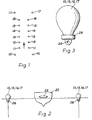
- the course to be traversed by a boat 20 is defined by successive pairs of buoys 10-17.
- the buoys 10 constitute an entrance gate
- the buoys 17 constitute an exit gate and the remaining pairs of buoys act as guides.
- the roles of the buoys 10 and 17 are reversed.
- Each of the buoys 10, 13, 14 and 17 is provided with a permanent magnet for detection by a sensor 22 mounted on the boat.
- each buoy is generally rotationally symmetric about a vertical axis and may be manufactured as a plastics moulding.
- Each buoy is formed with a through bore at its lower end for reception of a pin 24 or the like by means of which the buoy can be anchored in place.
- the permanent magnet can be mounted in any suitable manner, as shown in Figure 3, the permanent magnet is conveniently in the form of a ring magnet which fits over the reduced diameter lower end of the buoy and is held in place by the pin 24.
- the magnet 26 is arranged with its polar axis substantially vertical and produces a substantially isotropic magnetic field with respect to the vertical axis so that detection of the magnets by the sensor 22 is not affected by rotation of the buoys.
- the sensor 22 is mounted within the boat so as to be substantially horizontal and the sensor axis is directed generally endwise-on towards the magnets 26 associated with the buoys 10, 13, 14 and 17 disposed on either side of the boat.
- the magnets are all of substantially the same field strength and, it will be noted, are located beneath water level. Because the magnets all have the same strength and are located on both sides of the course, the sensor 22 can detect at least one or the other of each pair 10, 13, 14 and 17 irrespective of the precise path followed by the boat as it traverses the course. This can be important because the forces exerted by the skier in practice can be quite substantial and may cause the boat to deviate from a central path between the buoys.
- the senor includes an electrical coil 32 wound on a cylindrical former 34 having end flanges 36.
- the coil has a core of magnetically permeable material constituted, by one or more ferrite rods 38 arranged in the manner shown so that the rod projects substantially beyond at least one and preferably end of the coil.
- This arrangement of the core has, as previously mentioned, been found to give a pronounced directional effect, i.e. the sensor being considerably more sensitive to magnetic sources lying along its axis.
- any extraneous magnetic fields emanating from the boat engine and electrical ancillaries may be eliminated.
- an EMF will be induced in the coil 32 and this signal may be processed by the circuitry shown in Figure 6 so as to provide control signals for a timing device.
- the coil signal is fed to an amplifier 40 to increase the signal level and then to a filter 42 for filtering out extraneous signals.
- the circuitry may include a suitable feedback loop (not specifically shown) so as to filter out other undesirable transient signals which may arise from, for example, the ignition coil and alternator.
- the filtered signal is applied to a threshold detector 44 which may be in the form of a Schmitt trigger so that the detector 44 only produces an output in response to an input signal whose magnitude exceeds the threshold level (which may be adjustable).
- the output of the detector 44 is connected to a monostable multivibrator 46 which, in response to an output signal from the detector, provides a short duration pulse (for example 0.25 seconds) which is fed to a discriminator 48.
- the discriminator 48 serves to determine whether the pulse produced by the multivibrator 46 is the first, second, third or fourth of a series generated during one traverse of the course by the boat. If the pulse corresponds to movement of the boat past the buoys 10 and therefore constitutes the first pulse, the discriminator 48 produces simultaneous signals which are fed to two timers 50, 52 so as to initiate timing by both timers. In response to the second pulse, the discriminator stops the timer 50 and also a display 54 associated with the timer 50.
- the second pulse corresponds to movement of the boat past the buoys 13 and therefore the time recorded on the display 54 represents the time taken for the boat to move from buoys 10 to buoys 14.
- the third pulse detected as the boat moves past the buoys 14 is ignored when the boat is travelling in the direction of the arrow.
- the discriminator 48 stops timing of the timer 52 and also the display 56 associated with timer 52 thereby recording on display 56 the time taken for the boat to move from buoys 10 to buoys 17.
- the displays 54, 56 may display actual time elapsed or the time recorded may be translated into average speed and displayed as such.
- the display 54 provides a mid-course indication of the boat speed and the display 56 provides an overall indication of boat speed.
- the content of the displays 54 and 56 may be maintained until deliberately reset by means of a reset button accessible to an official.
- the reset button will be operated between successive runs after the times on the displays 54 and 56 have been noted.
- the reset may take place automatically, e.g. after expiry of a predetermined time.
- the magnets are mounted on the buoys. However, they may be associated with the buoys in other ways, e.g. clipped on, suspended from or mounted within the buoys.
- the invention provides an automatic timing system which, as well as providing an indication of the average boat speed over the complete course, may also provide a mid-course indication so that if as that stage the boat speed deviates from the prescribed speed, suitable adjustment can be made in order to compensate for the deviation and achieve an overall speed within the prescribed limits.
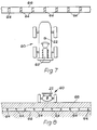
- the senor 22 may be constructed in the manner described hereinbefore but, in this case, is mounted on a racing car 60 preferably at a location spaced well away from the engine 62 and with the coil axis disposed predominantly (and preferably substantially) vertically.
- a plurality of magnets 64 are arranged in spaced relation lengthwise of the start/finish line and hence widthwise of the track. As shown, the magnets 64 are located within one or more tubes 66 embedded below ground level 68.
- the magnets 64 are spaced apart at intervals of about 18 inches and are arranged with their polar axes extending substantially horizontally so that the sensor coils of the car 60 have their axes presented endwise on to the polar axes of the magnet 64.
- Each car in addition to a sensor 22, will also incorporate circuitry similar to that shown in Figure 6 so as to provide the driver with a display of lap time and/or speed.
- the timers will be operated alternately so that at the end of each lap the signal produced by the sensor 22 is used to start one timer and stop the other timer which will have been started at the beginning of the lap, the discriminator 48 serving to control alternate operation of the two timers.
- the discriminator 48 serving to control alternate operation of the two timers.
- the previously non-operable timer is rendered operable, the time recorded by the timer which has been effective during that circuit is transferred to the display in the form of a time and/or speed read-out and the latter timer is reset.
- the display is subsequently updated at the completion of the next lap according to the time recorded by the other timer. In this manner, by appropriate location of the display within the car the driver can readily monitor lap times and/or speeds without having to rely on trackside timing and display.
- An important advantage provided by the system according to the invention is that the times/speeds for each lap are made available to each driver immediately upon completion of the lap. With conventional trackside timing, such information is always one lap behind which therefore detracts from its value.
- the timing data recorded on-board may be communicated to an external location, e.g. the "pits" in the case of car racing or the “jury tower” in the case of water slalom skiing.
- the system may include an on-board radio transmitter or transmitter/receiver and an external radio receiver or transmitter/receiver for location at the pits or the jury tower.
Landscapes
- Physics & Mathematics (AREA)
- General Physics & Mathematics (AREA)
- Toys (AREA)
- Control Of Position, Course, Altitude, Or Attitude Of Moving Bodies (AREA)
Applications Claiming Priority (4)
| Application Number | Priority Date | Filing Date | Title |
|---|---|---|---|
| GB8020899 | 1980-06-26 | ||
| GB8020899A GB2079496A (en) | 1980-06-26 | 1980-06-26 | Automatically controlled timing system |
| GB8113188A GB2081937A (en) | 1980-06-26 | 1981-04-29 | A timing system |
| GB8113188 | 1981-04-29 |
Publications (1)
| Publication Number | Publication Date |
|---|---|
| EP0043671A1 true EP0043671A1 (de) | 1982-01-13 |
Family
ID=26276002
Family Applications (1)
| Application Number | Title | Priority Date | Filing Date |
|---|---|---|---|
| EP81302814A Withdrawn EP0043671A1 (de) | 1980-06-26 | 1981-06-23 | Zeitmess-System |
Country Status (3)
| Country | Link |
|---|---|
| US (1) | US4392122A (de) |
| EP (1) | EP0043671A1 (de) |
| GB (1) | GB2081937A (de) |
Cited By (6)
| Publication number | Priority date | Publication date | Assignee | Title |
|---|---|---|---|---|
| WO1990013069A1 (en) * | 1989-04-21 | 1990-11-01 | Joakim Birgerson | Method and device for time measuring |
| EP0432180A4 (en) * | 1988-08-12 | 1992-01-02 | Dorian Industries Pty. Ltd. | Timing apparatus |
| AU648491B3 (en) * | 1993-11-24 | 1994-04-21 | Slendle Pty Ltd | Gauge for a gas cylinder |
| BE1006849A5 (fr) * | 1993-06-30 | 1995-01-03 | Alfano Angelo | Systeme chronometrique place sur une machine de competition ou autres permettant a l'utilisateur de visualiser instantanement et avec precision les releves de ses performances effectuees |
| EP0708388A3 (de) * | 1994-10-21 | 1997-11-12 | Shoichi Shinozuka | Choronograph und Zeitaufnahmevorrichtung |
| EP1376272A3 (de) * | 2002-06-20 | 2007-11-14 | ASTRA Gesellschaft für Asset Management mbH & Co. KG | Verfahren und Vorrichtung zur automatischen Zeitnahme bei sportlichen Massenveranstaltungen |
Families Citing this family (19)
| Publication number | Priority date | Publication date | Assignee | Title |
|---|---|---|---|---|
| JPS58167237A (ja) * | 1982-03-26 | 1983-10-03 | Koichi Nakamura | 自動車等の運転時間報知器 |
| GB2117937A (en) * | 1982-04-23 | 1983-10-19 | Redvers Albert Hocken | A timing system |
| US4764111A (en) * | 1985-11-21 | 1988-08-16 | Knierim Rupert W | Reminder and enforcer apparatus |
| US5342042A (en) * | 1987-06-30 | 1994-08-30 | Caldone Pty. Limited | Ball location system |
| US4999604A (en) * | 1988-02-26 | 1991-03-12 | Crews Eric J | Timing system |
| US4857886A (en) * | 1988-02-26 | 1989-08-15 | Crews Eric J | Timing system |
| WO1990014643A1 (en) * | 1989-05-15 | 1990-11-29 | Redback Electronics Pty Ltd. | Timing apparatus particularly for racing vehicles |
| AU636891B2 (en) * | 1989-05-15 | 1993-05-13 | Redback Electronics Pty. Ltd. | Timing apparatus particularly for racing vehicles |
| US5194861A (en) * | 1990-02-20 | 1993-03-16 | Scientific Racing Equipment, Inc. | On board timer system for a racing vehicle |
| US5136621A (en) * | 1990-12-11 | 1992-08-04 | Mitchell David E | Timing and lap counting device for a swimmer |
| US5130955A (en) * | 1990-12-11 | 1992-07-14 | Dean Luerker | Athletic timer correction system |
| US5276660A (en) * | 1992-05-29 | 1994-01-04 | Lee Richard D | Competition waterskier timing system |
| US5491476A (en) * | 1993-10-01 | 1996-02-13 | Dibella; James A. | Magnetically triggered elapsed time indicator |
| US5588889A (en) * | 1995-05-01 | 1996-12-31 | Easter; Scott D. | Timing buoy with remote timing capability |
| JP2004016538A (ja) * | 2002-06-18 | 2004-01-22 | Kunihiro Kishida | 計時システム |
| US9052717B1 (en) | 2004-02-11 | 2015-06-09 | Enovation Controls, Llc | Watercraft speed control device |
| US20080243321A1 (en) * | 2005-02-11 | 2008-10-02 | Econtrols, Inc. | Event sensor |
| US9207675B1 (en) | 2005-02-11 | 2015-12-08 | Enovation Controls, Llc | Event sensor |
| CN112308999A (zh) * | 2019-07-30 | 2021-02-02 | 北京八迈科技有限公司 | 车辆计时方法、计时传感器和接收器、客户端及计时系统 |
Citations (6)
| Publication number | Priority date | Publication date | Assignee | Title |
|---|---|---|---|---|
| GB191225487A (en) * | 1912-11-06 | 1913-10-02 | Alexander Greig Noble | Indicating Apparatus for Indicating the Speed of a Vessel Irrespective of a Tide or of a Current. |
| US3572711A (en) * | 1966-03-21 | 1971-03-30 | Thomas H Conklin | Timer and lap counter for slot cars |
| US3609678A (en) * | 1969-04-28 | 1971-09-28 | Minnesota Mining & Mfg | Magnetized means for providing control information to moving vehicles |
| US3748580A (en) * | 1970-11-13 | 1973-07-24 | Harmon Electronics Inc | Elapsed time and terminal speed computer for automotive vehicles |
| FR2213376A2 (de) * | 1970-06-03 | 1974-08-02 | Tuffet Pierre | |
| DE2854773A1 (de) * | 1978-01-02 | 1979-07-12 | Erich Bieramperl | Zeitmess- und anzeigevorrichtung |
Family Cites Families (3)
| Publication number | Priority date | Publication date | Assignee | Title |
|---|---|---|---|---|
| US2351707A (en) * | 1944-06-20 | Automatic electric self-posting | ||
| US3742195A (en) * | 1971-11-03 | 1973-06-26 | W Randle | Rally race computer |
| US3980868A (en) * | 1975-04-04 | 1976-09-14 | Thompson Francis T | Digital yacht racing timing system |
-
1981
- 1981-04-29 GB GB8113188A patent/GB2081937A/en not_active Withdrawn
- 1981-06-23 EP EP81302814A patent/EP0043671A1/de not_active Withdrawn
- 1981-06-25 US US06/277,399 patent/US4392122A/en not_active Expired - Fee Related
Patent Citations (6)
| Publication number | Priority date | Publication date | Assignee | Title |
|---|---|---|---|---|
| GB191225487A (en) * | 1912-11-06 | 1913-10-02 | Alexander Greig Noble | Indicating Apparatus for Indicating the Speed of a Vessel Irrespective of a Tide or of a Current. |
| US3572711A (en) * | 1966-03-21 | 1971-03-30 | Thomas H Conklin | Timer and lap counter for slot cars |
| US3609678A (en) * | 1969-04-28 | 1971-09-28 | Minnesota Mining & Mfg | Magnetized means for providing control information to moving vehicles |
| FR2213376A2 (de) * | 1970-06-03 | 1974-08-02 | Tuffet Pierre | |
| US3748580A (en) * | 1970-11-13 | 1973-07-24 | Harmon Electronics Inc | Elapsed time and terminal speed computer for automotive vehicles |
| DE2854773A1 (de) * | 1978-01-02 | 1979-07-12 | Erich Bieramperl | Zeitmess- und anzeigevorrichtung |
Cited By (7)
| Publication number | Priority date | Publication date | Assignee | Title |
|---|---|---|---|---|
| EP0432180A4 (en) * | 1988-08-12 | 1992-01-02 | Dorian Industries Pty. Ltd. | Timing apparatus |
| WO1990013069A1 (en) * | 1989-04-21 | 1990-11-01 | Joakim Birgerson | Method and device for time measuring |
| BE1006849A5 (fr) * | 1993-06-30 | 1995-01-03 | Alfano Angelo | Systeme chronometrique place sur une machine de competition ou autres permettant a l'utilisateur de visualiser instantanement et avec precision les releves de ses performances effectuees |
| EP0632350A1 (de) * | 1993-06-30 | 1995-01-04 | Angelo Alfano | Auf Kompetitionsmachinen oder dergleichen montiertes Chronometer, das der Benutzer eine sofortige und präzise Anzeige der Aufgenommene Daten seiner geschaffenen Leistung sehen lässt |
| AU648491B3 (en) * | 1993-11-24 | 1994-04-21 | Slendle Pty Ltd | Gauge for a gas cylinder |
| EP0708388A3 (de) * | 1994-10-21 | 1997-11-12 | Shoichi Shinozuka | Choronograph und Zeitaufnahmevorrichtung |
| EP1376272A3 (de) * | 2002-06-20 | 2007-11-14 | ASTRA Gesellschaft für Asset Management mbH & Co. KG | Verfahren und Vorrichtung zur automatischen Zeitnahme bei sportlichen Massenveranstaltungen |
Also Published As
| Publication number | Publication date |
|---|---|
| GB2081937A (en) | 1982-02-24 |
| US4392122A (en) | 1983-07-05 |
Similar Documents
| Publication | Publication Date | Title |
|---|---|---|
| US4392122A (en) | Magnetically triggered on-board elapsed time indicator | |
| US4089057A (en) | Method and device for measuring jump-lengths on a ski-jump | |
| US5034673A (en) | Method of moving and guiding golf cart | |
| FR2624618B1 (fr) | Dispositif de mesure de valeurs electromagnetiques d'une bobine et, en particulier, de mesure de la position de l'armature d'un systeme magnetique a bobine/armature | |
| EP2718906B1 (de) | System zur erfassung der position eines gegenstandes | |
| US3710246A (en) | Automobile timer | |
| US20170195642A1 (en) | Device and method for detecting, monitoring and/or controlling racing vehicles | |
| DE10029456A1 (de) | Verfahren zur Eichung eines Sensorsystems | |
| US3745450A (en) | Metal detection system for indicating the motion and direction of motion of a body having magnetic properties | |
| DE3327706A1 (de) | Verfahren und einrichtungen zur automatischen ermittlung der geschwindigkeit und identitaet von dicht folgenden fahrzeugen | |
| EP0782723A1 (de) | Führungssystem für ein selbstfahrendes fahrzeug mit getrennter, mobiler sendeeinrichtung und verfahren zum steuern des fahrzeugs | |
| EP0720764B1 (de) | Anlage zur erfassung der von einem kraftfahrzeug zurückgelegten wegstrecke | |
| GB2376585A (en) | Determining position and speed | |
| HRP20010801A2 (en) | Method for measuring the speed of a rail vehicle and installation therefor | |
| Tachi et al. | Guide dog robot—its basic plan and some experiments with MELDOG MARK I | |
| KR101112607B1 (ko) | 어레이 자기센서를 이용한 차량 위치검출 시스템 | |
| GB2079496A (en) | Automatically controlled timing system | |
| GB2117937A (en) | A timing system | |
| DE3702429C2 (de) | ||
| US5338036A (en) | Golf exercising aid device | |
| US4280694A (en) | Race track lure speed control assembly | |
| US5272435A (en) | Apparatus for timing aquatic craft for water skiing competition | |
| JP2521430B2 (ja) | ゴルフ用搬車走行誘導法 | |
| US5276660A (en) | Competition waterskier timing system | |
| US4441196A (en) | Speed independent system for obtaining preselected numbers of samples from object moving along fixed path |
Legal Events
| Date | Code | Title | Description |
|---|---|---|---|
| PUAI | Public reference made under article 153(3) epc to a published international application that has entered the european phase |
Free format text: ORIGINAL CODE: 0009012 |
|
| AK | Designated contracting states |
Designated state(s): AT BE CH DE FR IT LU NL SE |
|
| 17P | Request for examination filed |
Effective date: 19820608 |
|
| STAA | Information on the status of an ep patent application or granted ep patent |
Free format text: STATUS: THE APPLICATION IS DEEMED TO BE WITHDRAWN |
|
| 18D | Application deemed to be withdrawn |
Effective date: 19840112 |