EP0043604A1 - Time switch - Google Patents
Time switch Download PDFInfo
- Publication number
- EP0043604A1 EP0043604A1 EP81200626A EP81200626A EP0043604A1 EP 0043604 A1 EP0043604 A1 EP 0043604A1 EP 81200626 A EP81200626 A EP 81200626A EP 81200626 A EP81200626 A EP 81200626A EP 0043604 A1 EP0043604 A1 EP 0043604A1
- Authority
- EP
- European Patent Office
- Prior art keywords
- spring
- switching pin
- switch
- memory alloy
- circuit breaker
- Prior art date
- Legal status (The legal status is an assumption and is not a legal conclusion. Google has not performed a legal analysis and makes no representation as to the accuracy of the status listed.)
- Withdrawn
Links
Images

Classifications
-
- H—ELECTRICITY
- H01—ELECTRIC ELEMENTS
- H01H—ELECTRIC SWITCHES; RELAYS; SELECTORS; EMERGENCY PROTECTIVE DEVICES
- H01H43/00—Time or time-programme switches providing a choice of time-intervals for executing one or more switching actions and automatically terminating their operations after the programme is completed
- H01H43/30—Time or time-programme switches providing a choice of time-intervals for executing one or more switching actions and automatically terminating their operations after the programme is completed with timing of actuation of contacts due to thermal action
- H01H43/301—Time or time-programme switches providing a choice of time-intervals for executing one or more switching actions and automatically terminating their operations after the programme is completed with timing of actuation of contacts due to thermal action based on the expansion or contraction of a material
- H01H43/302—Time or time-programme switches providing a choice of time-intervals for executing one or more switching actions and automatically terminating their operations after the programme is completed with timing of actuation of contacts due to thermal action based on the expansion or contraction of a material of solid bodies
-
- H—ELECTRICITY
- H01—ELECTRIC ELEMENTS
- H01H—ELECTRIC SWITCHES; RELAYS; SELECTORS; EMERGENCY PROTECTIVE DEVICES
- H01H61/00—Electrothermal relays
- H01H61/01—Details
- H01H61/0107—Details making use of shape memory materials
-
- H—ELECTRICITY
- H01—ELECTRIC ELEMENTS
- H01H—ELECTRIC SWITCHES; RELAYS; SELECTORS; EMERGENCY PROTECTIVE DEVICES
- H01H61/00—Electrothermal relays
- H01H61/01—Details
- H01H61/0107—Details making use of shape memory materials
- H01H2061/0115—Shape memory alloy [SMA] actuator formed by coil spring
Definitions
- the invention is based on a timer according to the preamble of the claim.
- Thermal timers have long been known (DE-PS 705 383, DE-OS.25 44 758). They mostly work on the principle of a bimetal strip or any expansion element, which changes its shape as a function of temperature after a certain time, which is determined by the thermal and electrical characteristics. In this way the device is activated which switches the circuit on or off.
- Shape memory alloys per se are also known from numerous publications, which should not be listed again here specifically.
- the main types are Ni / Ti / Cu, Cu / Al / Ni and Cu / Zn / Al.
- the following table shows the physical properties of such memory alloys and compared to those of the bimetal strip Fe / Ni.
- the conventional timers are characterized by the fact that the active element (bimetal strip or body that expands under the influence of temperature) changes its shape very little when there are changes in temperature, and this change also takes place continuously. This makes the switches bulky and expensive, and the mechanisms determining the switch-on time can only be carried out with great difficulty. Due to the absence of a temperature Hysteresis of the active element requires an additional mechanism to ensure that the switch is switched on and off clearly. There is therefore a great need to improve and simplify timers over conventional designs.
- the invention has for its object to provide a timer that allows inexpensive manufacture with the simplest possible structure and the highest level of accuracy and operational reliability.
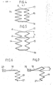
- Fig. 1 the structure of the timer in the basic position is shown schematically in principle.
- l are the current supply terminals' for the mains connection (direct and alternating current network), the fixed contacts 2 and 3, the movable contact of a circuit breaker, such as a lamp is fed as a load 4 via the.
- the circuit In the basic position, the circuit is open. 5 represent the fixed contacts and 6 the movable contact piece of an auxiliary switch which feeds the element 8, consisting of a memory alloy and a counter spring, via a series resistor.
- the switch pins 10 and 11 for actuating the circuit breaker or auxiliary switch are seated on a traverse 9, so 12 is the push button for brief (fraction of a second) actuation and 13 the associated switch pin.
- Fig. 2 shows the same switch arrangement as Fig. 1, j-but at the moment of brief actuation of the push button 12, which presses the movable contact piece 3 to the fixed contacts 2 of the circuit breaker via the switching pin 13. As a result, the circuit is closed and the consumer 4 and the element 8 are switched on.
- the remaining reference numerals correspond to FIG. 1.
- Fig. 3 shows the switch structure with the circuits after setting the memory effect.
- the switching pins 10 and 11 are raised, so that the movable contact piece 3 of the circuit breaker is pressed against the fixed contacts 2, whereas the movable contact piece 6 of the auxiliary switch is lifted off the fixed contacts 5.
- the push button 12 with its switching pin 13 has fallen off.
- the circuit through the consumer 4 remains closed.
- Fig. 4 shows a schematic representation of a possible embodiment of the element 8 of Fig. 1 in the basic position (low temperature).
- This combined element consists of a compression spring 14 made of a shape memory alloy, which is capable of the two-way effect, and of a counter spring 15 designed as a tension spring.
- the two springs are each connected via a fixed plate 16 arranged below and an upper movable plate 17.
- the springs 14 and 15 can also be made in a different way, e.g. be arranged coaxially to each other.
- the force "F” exerted by this combination, which acts at point "A" is indicated by an arrow pointing upwards.
- FIG. 5 shows the combined element according to FIG. 4 in the position which results after the memory effect has been set. Due to the force exerted by the compression spring 14 on the movable plate 17, the point originally resting in "A” is now in "A '' '. The corresponding stroke” s "is indicated in the drawing by arrowheads.
- Fig. 6 shows a schematic representation of a combination ten element consisting of a spiral spring 18 made of a shape memory alloy and a tension spring designed as a tension spring 19 in the basic position (low temperature).
- the spiral spring 18 is totally clamped in the fixed piece 20, while the counter spring 19 is hooked into the fixed eyelet 21 at its lower end.
- FIG. 7 shows a schematic representation of the combined element according to FIG. 6 in the position after setting the memory effect (high temperature).
- the spiral spring 18 is curved upwards, so that its free end, on which the tension spring 19 engages, is increased by the stroke "s" compared to the basic position.
- the circuit breaker 2, 3 In the basic position, the circuit breaker 2, 3 is open and no current flows.
- the element 8 consisting. a spring made of memory alloy and a normal counter spring is at a temperature corresponding to the martensitic low-temperature phase, which is below the transition temperature M s .
- the push button 12 By briefly pressing (fraction of a second) the push button 12, the fixed contacts 2 of the circuit breaker are bridged by means of the movable contact piece 3 and the consumer 4 is connected to the mains.
- a current flows through the closed contacts 5 of the auxiliary switch and through the series resistor 7; which heats the element 8 either directly or indirectly within 100-500nsec-.
- the transition temperature is exceeded, the memory alloy tilts into the austenitic high-temperature phase, where it suddenly undergoes a considerable change in length.
- the element 8 expands in its longitudinal direction and pushes the switching pins 10 and 11 vertically upward via the crossmember 9.
- the temperature of element 8 has reached a value of 120-200 ° C, for example.
- the switching pin 10 presses the movable contact piece 3 of the circuit breaker against the contacts 2 and thus ensures that the power supply to the consumer 4 is maintained even after the pushbutton 12 has dropped off.
- the switching pin 11 opens the auxiliary switch and interrupts the power supply to the element 8. Further heating stops and the cooling process begins.
- the transition temperature eg approx.
- the element 8 contracts suddenly, with the switching pins 10 and 11 being pulled down over the crossmember 9.
- the movable contact piece 3 of the circuit breaker drops and interrupts the circuit.
- the contacts 5 of the auxiliary switch are closed.
- the starting position (basic position) according to FIG. 1 is thus restored.
- the cooling process takes, for example, in the present case, however, approximately 200 sec "can transition temperature, spring characteristics of the element 8 is set within certain limits by the physical data such as heat capacity, etc..
- the element 8 according to FIG. 1 essentially consisted of a compression spring 14 made of a memory alloy and a counter connected in parallel spring 15 (tension spring).
- the memory spring compression spring has the following characteristics:
- a resistance value of 3.3 ⁇ was chosen for the series resistor 7 (FIG. 1).
- the mains voltage was 220 V ⁇
- the heating-up time for the compression spring 14 until the memory effect was set was 100 msec.
- the spontaneous change in length (stroke "s") was 10 mm, the point "A” being raised under the influence of a force of 5 N to the point "A '".
- the value of 5 N relates to the excess force which, after deducting the force of the counter spring, was still available on average for actuating the switch.
- the temperature of the compression spring 14 was approximately 120 ° C.
- the time to reach the transition point of approximately 60 ° C. was 200 seconds. This time is determined by the cooling time plus the time which is necessary to supply the energy which brings about the conversion into the martensitic structure of the compression spring 14.
- the element 8 according to FIG. 1 essentially consisted of a spiral spring 18 made of a memory alloy with an insulated electrical heating element glued on and a counter spring 19 (tension spring).
- the spiral spring made of a memory alloy has the following characteristics:
- the mains voltage was 220 V ⁇
- the heating time for the spiral spring 18 until the memory effect was set to 500 msec.
- the spontaneous change in length (stroke "s") was 5 mm
- the mean excess force after deducting the force of the counter spring was 5 N.
- the temperature of the spiral spring 18 when the memory effect was set was 200 ° C.
- the corresponding temperature was 120 ° C.
- the device according to the invention made it possible to simplify the construction of timers where complicated mechanisms such as clockwork and the like are unnecessary. Thanks to the significant amplitude of the movement and the force of the memory effect as well as the hysteresis in function of the temperature, an accurate and reliable working of the device is guaranteed and maintenance is reduced.
Abstract
Zeitschalter mit die Wärmekapazität ausnutzendem Element (18) aus einer Gedächtnislegierung, welche den Zweiwegeffekt zeigt, wobei parallel zum Strompfad (4) ein Hilfsstromkreis angeordnet ist, welcher das Element (8) direkt oder indirekt heizt, so dass dieser sowohl auf einen Leistungsschalter (2, 3) wie einen Hilfsschalter (5, 6) einwirkt. Ausnutzung hoher Formänderungsarbeiten und Temperaturhysteresis der Gedächtnislegierung.Time switch with the heat capacity utilizing element (18) made of a memory alloy, which shows the two-way effect, with an auxiliary circuit being arranged parallel to the current path (4), which heats the element (8) directly or indirectly, so that it both switches to a circuit breaker (2 , 3) acts as an auxiliary switch (5, 6). Utilization of high deformation work and temperature hysteresis of the memory alloy.
Description
Die Erfindung geht aus von einem Zeitschalter nach der Gattung des Patentanspruchs.The invention is based on a timer according to the preamble of the claim.
Thermische Zeitschalter sind schon lange bekannt (DE-PS 705 383, DE-OS.25 44 758). Sie arbeiten meistens nach dem Prinzip eines Bimetallstreifens oder irgend eines Ausdehnungselementes, welches seine Form in Funktion der Temperatur nach einer gewissen Zeit verändert, welche durch die thermischen und elektrischen Kenndaten bestimmt ist. Auf diese Weise wird die Vorrichtung betätigt, welche den Stromkreis ein- oder ausschaltet.Thermal timers have long been known (DE-PS 705 383, DE-OS.25 44 758). They mostly work on the principle of a bimetal strip or any expansion element, which changes its shape as a function of temperature after a certain time, which is determined by the thermal and electrical characteristics. In this way the device is activated which switches the circuit on or off.
Ferner ist die Anwendung von Formgedächtnislegierungen zur Unterbrechung elektrischer Stromkreise bekannt. Die Temperaturregulierung, bei welcher sich der Gedächtsniseffekt abspielt, wobei eine Gegenfeder verwendet wird, ist ebenfalls beschrieben worden (CH-PS 616 270, EU 78200393.3).The use of shape memory alloys for interrupting electrical circuits is also known. The temperature regulation at which the memory effect takes place, using a counter spring, has also been described (CH-PS 616 270, EU 78200393.3).
Formgedächtnislegierungen an sich sind ebenfalls aus zahlreichen Publikationen bekannt, welche hier nicht nochmals speziell aufgeführt werden sollen. Es handelt sich dabei vor allem um die Typen Ni/Ti/Cu, Cu/Al/Ni und Cu/Zn/Al. In der nachfolgenden Tabelle sind die physikalischen Eigenschaften derartiger Gedächtnislegierungen aufgeführt und denjenigen vom Bimetallstreifen Fe/Ni gegenübergestellt.


Die herkömmlichen Zeitschalter zeichnen sich dadurch aus, dass das aktive Element(Bimetallstreifen oder sich unter Temperatureinfluss ausdehnenden Körper) seine Form bei Temperaturänderungen nur sehr wenig ändert und diese Aenderung ausserdem kontinuierlich erfolgt. Dadurch werden die Schalter voluminös und teuer, und die die Einschaltzeit bestimmenden Mechanismen sind nur unter grossen Schwierigkeiten ausführbar. Zufolge Abwesenheit einer TemperaturHysteresis des aktiven Elements ist zwecks Sicherstellung der eindeutigen Einschalt- und Ausschaltstellung des Schalters ein zusätzlicher Mechanismus notwendig. Es besteht daher ein grosses Bedürfnis zur Verbesserung und Vereinfachung von Zeitschaltern gegenüber den herkömmlichen Ausführungen.The conventional timers are characterized by the fact that the active element (bimetal strip or body that expands under the influence of temperature) changes its shape very little when there are changes in temperature, and this change also takes place continuously. This makes the switches bulky and expensive, and the mechanisms determining the switch-on time can only be carried out with great difficulty. Due to the absence of a temperature Hysteresis of the active element requires an additional mechanism to ensure that the switch is switched on and off clearly. There is therefore a great need to improve and simplify timers over conventional designs.
Der Erfindung liegt die Aufgabe zugrunde, einen Zeitschalter anzugeben, welcher bei möglichst einfachem Aufbau und einem Höchstmass an Genauigkeit und Betriebssicherheit eine preisgünstige Herstellung gestattet.The invention has for its object to provide a timer that allows inexpensive manufacture with the simplest possible structure and the highest level of accuracy and operational reliability.
Diese Aufgabe wird erfindungsgemäss durch die Merkmale des Patentanspruchs gelöst.According to the invention, this object is achieved by the features of the patent claim.
Die Erfindung wird anhand der nachfolgenden, durch Figuren erläuterten Ausführungsbeispiele beschrieben.The invention is described on the basis of the following exemplary embodiments explained by figures.
Dabei zeigt:
- Fig. 1 eine schematische Darstellung des Schalteraufbaus mit den Stromkreisen in der Grundstellung (Stromkreis geöffnet),
- Fig. 2 eine schematische Darstellung des Schalteraufbaus mit den Stromkreisen nach Einschalten über einen Druckknopf,
- Fig. 3 eine schematische Darstellung des Schalteraufbaus mit den Stromkreisen nach Einstellung des Gedächtniseffektes und Abfallen des Druckknopfes,
- Fig. 4 eine schematische Darstellung eines kombinierten Elementes bestehend aus Druckfeder aus Gedächtnislegierung und Gegenfeder in der Grundstellung (tiefe Temperatur),
- Fig. 5 eine schematische Darstellung eines kombinierten Elementes gemäss Fig. 4 in der Stellung nach Einstellen des Gedächtniseffektes (hohe Temperatur),
- Fig. 6 eine schematische Darstellung eines kombinierten Elementes bestehend aus Biegefeder aus Gedächtnislegierung und Gegenfeder in der Grundstellung (tiefe Temperatur),
- Fig. 7 eine schematische Darstellung eines kombinierten Elementes gemäss Fig. 6 in der Stellung nach Einstellen des Gedächtniseffektes (hohe Temperatur).
- 1 is a schematic representation of the switch structure with the circuits in the basic position (circuit open),
- 2 is a schematic representation of the switch structure with the circuits after switching on via a push button,
- 3 is a schematic representation of the switch structure with the circuits after setting the memory effect and dropping the push button,
- 4 is a schematic representation of a combined element consisting of a compression spring made of memory alloy and a counter spring in the basic position (low temperature),
- 5 shows a schematic representation of a combined element according to FIG. 4 in the position after setting the memory effect (high temperature),
- 6 is a schematic representation of a combined element consisting of a spiral spring made of memory alloy and a counter spring in the basic position (low temperature),
- Fig. 7 is a schematic representation of a combined element according to Fig. 6 in the position after setting the memory effect (high temperature).
In Fig. l ist der Aufbau des Zeitschalters in der Grundstellung im Prinzip schematisch dargestellt. l sind die Stromzuführungsklemmen' für den Netzanschluss (Gleich-und Wechselstromnetz), 2 die festen Kontakte und 3 das bewegliche Kontaktstück eines Leistungsschalters, über den beispielsweise eine Lampe als Verbraucher 4 gespeist wird. In der Grundstellung ist der Stromkreis geöffnet. 5 stellen die festen Kontakte und 6 das bewegliche Kontaktstück eines Hilfsschalters dar, welcher über einen Vorwiderstand das Element 8, bestehend aus einer Gedächtnislegierung und einer Gegenfeder speist. Auf einer Traverse 9 sitzen die Schaltstifte 10 und 11 für die Betätigung des Leistungs- bzw. Hilfsschalterso 12 ist der Druckknopf für kurzzeitige (Bruchteil einer Sekunde) Betätigung und 13 der dazugehörige Schaltstift.In Fig. 1, the structure of the timer in the basic position is shown schematically in principle. l are the current supply terminals' for the mains connection (direct and alternating current network), the
Fig. 2 zeigt die gleiche Schalteranordnung wie Fig. 1, j-doch im Moment der kurzzeitigen Betätigung des Druckknopfes 12, welcher über den Schaltstift 13 das bewegliche Kontaktstück 3 an die festen Kontakte 2 des Leistungsschalters drückt. Dadurch ist der Stromkreis geschlossen und der Verbraucher 4 sowie das Element 8 eingeschaltet. Die übrigen Bezugszeichen entsprechen der Fig. l.Fig. 2 shows the same switch arrangement as Fig. 1, j-but at the moment of brief actuation of the
Fig. 3 zeigt den Schalteraufbau mit den Stromkreisen nach Einstellung des Gedächtniseffektes. In dieser Stellung sind die Schaltstifte 10 und 11 angehoben, sodass das bewegliche Kontaktstück 3 des Leistungsschalters gegen die festen Kontakte 2 gedrückt wird, wogegen das bewegliche Kontaktstück 6 des Hilfsschalters von den festen Kontakten 5 abgehoben wird. Der Druckknopf 12 mit seinem Schaltstift 13 ist abgefallen. Der Stromkreis über den Verbraucher 4 bleibt geschlossen.Fig. 3 shows the switch structure with the circuits after setting the memory effect. In this position, the
Fig. 4 zeigt eine schematische Darstellung einer möglichen Ausführung des Elementes 8 der Fig. 1 in der Grundstellung (tiefe Temperatur). Dieses kombinierte Element besteht aus einer Druckfeder 14 aus einer Formgedächtnislegierung, welche zum Zweiwegeffekt befähigt ist, sowie aus einer als Zugfeder ausgebildeten Gegenfeder 15. Die beiden Federn sind je über eine unten angeordnete feste Platte 16 und eine obere bewegliche Platte 17 verbunden. Selbstverständlich können die Federn 14 und 15 auch auf eine andere Art, z.B. koaxial zueinander angeordnet sein. Die von dieser Kombination ausgeübte Kraft "F", welche im Punkt "A" angreift, ist durch einen nach oben gerichteten Pfeil angedeutet.Fig. 4 shows a schematic representation of a possible embodiment of the element 8 of Fig. 1 in the basic position (low temperature). This combined element consists of a
In Fig. 5 ist das kombinierte Element gemäss Fig. 4 in derjenigen Stellung dargestellt, die sich nach Einstellen des Gedächtniseffektes ergibt. Durch die von der Druckfeder 14 auf die bewegliche Platte 17 ausgeübte Kraft, befindet sich der ursprünglich in "A" ruhende Punkt nun in "A'''. Der entsprechende Hub "s" ist in der Zeichnung durch Pfeilspitzen angedeutet.5 shows the combined element according to FIG. 4 in the position which results after the memory effect has been set. Due to the force exerted by the
Fig. 6 zeigt eine schematische Darstellung eines kombinierten Elementes bestehend aus einer Biegefeder 18 aus einer Formgedächtnislegierung und einer als Zugfeder ausgebildeten Gegenfeder 19 in der Grundstellung (tiefe Temperatur). Die Biegefeder 18 ist im festen Stück 20 total eingespannt, während die Gegenfeder 19 an ihrem unteren Ende in die feste Oese 21 eingehängt ist.Fig. 6 shows a schematic representation of a combination ten element consisting of a
Fig. 7 zeigt in schematischer Darstellung das kombinierte Element gemäss Fig. 6 in der Stellung nach Einstellen des Gedächtniseffektes (hohe Temperatur). Die Biegefeder 18 ist nach oben gekrümmt, sodas's ihr freies Ende, an dem die Zugfeder 19 angreift, gegenüber der Grundstellung um den Hub "s" erhöht ist.FIG. 7 shows a schematic representation of the combined element according to FIG. 6 in the position after setting the memory effect (high temperature). The
In der Grundstellung ist der Leistungsschalter 2, 3 geöffnet und es fliesst kein Strom. Das Element 8 bestehend . aus einer Feder aus Gedächtnislegierung und einer normalen Gegenfeder befindet sich-auf einer der martensitischen Tieftemperaturphase entsprechenden Temperatur, welche unterhalb der Umwandlungstemperatur Ms liegt. Durch kurzzeitiges Betätigen (Bruchteil einer Sekunde) des Druckknopfes 12 werden die festen Kontakte2 des Leistungsschalters mittels des beweglichen Kontaktstückes 3 überbrückt und der Verbraucher 4 an das Netz angeschlossen. Gleichzeitig fliesst über die geschlossenen Kontakte 5 des Hilfsschalters und über den Vorwiderstand 7 ein Strom; welcher das Element 8 entweder auf direktem oder indirektem Wege innert 100-500nsec- erwärmt. Bei Ueberschreitung der Umwandlungstemperatur kippt die Gedächtnislegierung in die austenitische Hochtemperaturphase um, wobei sie sprunghaft eine beträchtliche Längenänderung erleidet.In the basic position, the
Im vorliegenden Fall dehnt sich das Element 8 in seiner Längsrichtung aus und schiebt über die Traverse 9 die Schaltstifte 10 und 11 vertikal nach oben. In diesem Moment hat die Temperatur des Elementes 8 beispielsweise einen Wert von 120-200°C erreicht. Der Schaltstift 10 drückt das bewegliche Kontaktstück 3 des Leistungsschalters gegen die Kontakte 2 und sorgt damit auch nach Abfallen des Druckknopfes 12 für die Aufrechterhaltung der Stromzuführung zum Verbraucher 4. Gleichzeitig öffnet der Schaltstift 11 den Hilfsschalter und unterbricht die Stromzuführung zum Element 8. Die weitere Erwärmung hört auf und der Abkühlungsvorgang beginnt. Nach beispielsweise ca. 200 sea ist die Umwandlungstemperatur (z.B. ca. 60°C) erreicht und der spontane inverse Gedächtniseffekt stellt sich ein: Das Element 8 zieht sich sprunghaft zusammen, wobei die Schaltstifte 10 und 11 über die Traverse 9 nach unten gezogen werden. Das bewegliche Kontaktstück 3 des Leistungsschalters fällt ab und unterbricht den Stromkreis. Gleichzeitig werden die Kontakte 5 des Hilfsschalters geschlossen. Damit ist die Ausgangslage (Grundstellung) gemäss Fig. 1 wieder hergestellt. Der Abkühlungsvorgang dauert beispielsweise im vorliegenden Fall ca. 200 sec" kann jedoch durch die physikalischen Daten wie Umwandlungstemperatur, Wärmekapazität, Federeigenschaften etc. des Elementes 8 innerhalb gewisser Grenzen eingestellt werden.In the present case, the element 8 expands in its longitudinal direction and pushes the
In dieser Ausführungsform bestand das Element 8 gemäss Fig. 1 im wesentlichen aus einer Druckfeder 14 aus einer Gedächtnislegierung und einer parallelgeschalteten Gegenfeder 15 (Zugfeder). Die Druckfeder aus Gedächtnislegierung weist folgende Kenndaten auf:In this embodiment, the element 8 according to FIG. 1 essentially consisted of a


Für den Vorwiderstand 7 (Fig. l) wurde ein Widerstandswert von 3,3 Ω gewählt. Die Netzspannung betrug 220 V ~, die Aufheizdauer für die Druckfeder 14 bis zur Einstellung des Gedächtniseffektes war 100 msec. Die spontane Längenänderung (Hub "s") betrug 10 mm, wobei der Punkt "A" unter dem Einfluss einer Kraft von 5 N auf den Punkt "A'" angehoben wurde. Der Wert von 5 N bezieht sich dabei auf die Ueberschusskraft, welche nach Abzug der Kraft der Gegenfeder im Mittel noch zur Betätigung des Schalters zur Verfügung stand. Im Augenblick der maximalen Erwärmung bei der Einschaltung des Gedächtniseffektes betrug die Temperatur der Druckfeder 14 ca. 120°C. Die Zeit bis zum Erreichen des Umwandlungspunktes von ca. 60°C betrug 200 sec. Diese Zeit wird bestimmt durch die Abkühlungszeit plus die Zeit, welche notwendig ist, um die Energie zuzuführen, die die Umwandlung in die martensitische Struktur der Druckfeder 14 herbeiführt.A resistance value of 3.3 Ω was chosen for the series resistor 7 (FIG. 1). The mains voltage was 220 V ~, the heating-up time for the
Das Element 8 gemäss Fig. 1 bestand im wesentlichen aus einer Biegefeder 18 aus einer Gedächtnislegierung mit aufgeklebtem isolierten elektrischen Heizelement und einer Gegenfeder 19 (Zugfeder). Die aus einer Gedächtnislegierung bestehende Biegefeder weist folgende Kenndaten auf:


Die Netzspannung betrug 220 V ~ , die Aufheizdauer für die Biegefeder 18 bis zur Einstellung des Gedächtniseffektes war 500 msec. Die spontane Längenänderung (Hub "s") betrug 5mm, die mittlere Ueberschusskraft nach Abzug der Kraft der Gegenfeder 5 N. Die Temperatur der Biegefeder 18 bei Einstellung des Gedächtniseffektes betrug 200°C. Die gesamte Zeit bis zum Erreichen des Umwandlungspunktes, wo die β-Phase in den martensitischen Zustand umklappt, wurde mit 200 sec festgestellt. Die entsprechende Temperatur betrug 120°C.The mains voltage was 220 V ~ , the heating time for the
Durch die erfindungsgemässe Vorrichtung wurde eine konstruktive Vereinfachung für Zeitschalter ermöglicht, wobei sich komplizierte Mechanismen wie Uhrwerke und dergleichen erübrigen. Dank bedeutender Amplitude des Bewegungsablaufs und der Kraftwirkung des Gedächtniseffektes sowie der Hysteresis in Funktion der Temperatur wird ein genaues und betriebssicheres Arbeiten des Apparates gewährleistet und die Wartung herabgesetzt.The device according to the invention made it possible to simplify the construction of timers where complicated mechanisms such as clockwork and the like are unnecessary. Thanks to the significant amplitude of the movement and the force of the memory effect as well as the hysteresis in function of the temperature, an accurate and reliable working of the device is guaranteed and maintenance is reduced.
- 1 Stromzuführungsklemmen1 power supply terminals
- 2 Feste Kontakte des Leistungsschalters2 Fixed contacts of the circuit breaker
- 3 Bewegliches Kontaktstück des Leistungsschalters3 Movable contact piece of the circuit breaker
- 4 Verbraucher (Lampe)4 consumers (lamp)
- 5 Feste Kontakte des Hilfsschalters5 Fixed contacts of the auxiliary switch
- 6 Bewegliches Kontaktstück des Hilfsschalters6 Movable contact piece of the auxiliary switch
- 7 Vorwiderstand7 series resistor
- 8 Element aus Gedächtnislegierung und Gegenfeder8 Element made of memory alloy and counter spring
- 9 Traverse9 traverse
- 10 Schaltstift für Leistungsschalter10 Switching pin for circuit breakers
- 11 Schaltstift für Hilfsschalter11 Switch pin for auxiliary switches
- 12 Druckknopf12 push button
- 13 Schaltstift des Druckknopfes13 Switch pin of the push button
- 14 Druckfeder aus Formgedächtnislegierung (Zweiwegeffekt)14 compression spring made of shape memory alloy (two-way effect)
- 15 Gegenfeder (Zugfeder)15 counter spring (tension spring)
- 16 Feste Platte16 fixed plate
- 17 Bewegliche Platte17 Movable plate
- 18 Biegefeder aus Formgedächtnislegierung (Zweiwegeffekt)18 spiral spring made of shape memory alloy (two-way effect)
- 19 Gegenfeder (Zugfeder)19 counter spring (tension spring)
- 20 Festes Stück (Einspannstelle)20 fixed piece (clamping point)
- 21 Feste Oese21 Fixed eyelet
Claims (1)
Applications Claiming Priority (2)
| Application Number | Priority Date | Filing Date | Title |
|---|---|---|---|
| CH520680A CH627876A5 (en) | 1980-07-08 | 1980-07-08 | Timer. |
| CH5206/80 | 1980-07-08 |
Publications (1)
| Publication Number | Publication Date |
|---|---|
| EP0043604A1 true EP0043604A1 (en) | 1982-01-13 |
Family
ID=4289705
Family Applications (1)
| Application Number | Title | Priority Date | Filing Date |
|---|---|---|---|
| EP81200626A Withdrawn EP0043604A1 (en) | 1980-07-08 | 1981-06-09 | Time switch |
Country Status (4)
| Country | Link |
|---|---|
| US (1) | US4371791A (en) |
| EP (1) | EP0043604A1 (en) |
| JP (1) | JPS5744934A (en) |
| CH (1) | CH627876A5 (en) |
Cited By (1)
| Publication number | Priority date | Publication date | Assignee | Title |
|---|---|---|---|---|
| DE3842171A1 (en) * | 1988-12-15 | 1990-06-28 | Barlian Reinhold | DELAY RELAY |
Families Citing this family (5)
| Publication number | Priority date | Publication date | Assignee | Title |
|---|---|---|---|---|
| JPS6010299U (en) * | 1983-06-30 | 1985-01-24 | クロイ電機株式会社 | Fluorescent lighting device |
| JPH0654093B2 (en) * | 1985-03-12 | 1994-07-20 | マツダ株式会社 | Exhaust turbocharged engine |
| US5160917A (en) * | 1990-06-14 | 1992-11-03 | Iowa State University Research Foundation, Inc. | Energy beam position detector |
| US5105178A (en) * | 1991-04-19 | 1992-04-14 | Krumme John F | Over-current/over-temperature protection device |
| FR2715763B1 (en) * | 1994-02-01 | 1996-03-29 | Gec Alsthom T D Inc | Mechanism for actuating a protective switch-off chamber. |
Citations (2)
| Publication number | Priority date | Publication date | Assignee | Title |
|---|---|---|---|---|
| US3725835A (en) * | 1970-07-20 | 1973-04-03 | J Hopkins | Memory material actuator devices |
| US3959691A (en) * | 1973-04-16 | 1976-05-25 | Texas Instruments Incorporated | Motor protector |
Family Cites Families (3)
| Publication number | Priority date | Publication date | Assignee | Title |
|---|---|---|---|---|
| US3193711A (en) * | 1962-01-18 | 1965-07-06 | Collins Radio Co | Step-start circuit |
| US3371254A (en) * | 1965-10-01 | 1968-02-27 | Harold T. Hagfors | Safety control system |
| US3725644A (en) * | 1972-04-11 | 1973-04-03 | Barber Colman Co | Input switch for reversing the sense of an amplifier in a single loop heating-cooking system |
-
1980
- 1980-07-08 CH CH520680A patent/CH627876A5/en not_active IP Right Cessation
-
1981
- 1981-06-09 EP EP81200626A patent/EP0043604A1/en not_active Withdrawn
- 1981-07-01 JP JP56101387A patent/JPS5744934A/en active Pending
- 1981-07-06 US US06/280,487 patent/US4371791A/en not_active Expired - Fee Related
Patent Citations (2)
| Publication number | Priority date | Publication date | Assignee | Title |
|---|---|---|---|---|
| US3725835A (en) * | 1970-07-20 | 1973-04-03 | J Hopkins | Memory material actuator devices |
| US3959691A (en) * | 1973-04-16 | 1976-05-25 | Texas Instruments Incorporated | Motor protector |
Cited By (1)
| Publication number | Priority date | Publication date | Assignee | Title |
|---|---|---|---|---|
| DE3842171A1 (en) * | 1988-12-15 | 1990-06-28 | Barlian Reinhold | DELAY RELAY |
Also Published As
| Publication number | Publication date |
|---|---|
| US4371791A (en) | 1983-02-01 |
| JPS5744934A (en) | 1982-03-13 |
| CH627876A5 (en) | 1982-01-29 |
Similar Documents
| Publication | Publication Date | Title |
|---|---|---|
| DE3140472A1 (en) | Device for the operation of a bolt acted upon by a return spring | |
| EP0043604A1 (en) | Time switch | |
| DE60107264T2 (en) | Temperature monitor for a liquid heater | |
| DE2439066C2 (en) | Device for limiting currents | |
| DE604911C (en) | Arrangement for switching off an inductive resistor in a direct current circuit | |
| DE3823186C2 (en) | ||
| DE696668C (en) | ||
| DE2065212A1 (en) | ELECTRIC SWITCH | |
| DE933472C (en) | Electrothermally operated period switch | |
| AT374619B (en) | THERMAL SWITCH | |
| DE647699C (en) | Arrangement for the automatic operation of electrical resistance ovens, in which the heating coils of the oven are switched from delta to star connection by a temperature controller with a delay | |
| DE733607C (en) | Overcurrent monitoring device | |
| CH391057A (en) | Bimetal switch and use of the same | |
| DE457673C (en) | Automatic high-current switch, the working parts of which are arranged between two parallel plates | |
| DE935379C (en) | Maximum and minimum guard for electrical systems | |
| DE488688C (en) | Device for the automatic connection and disconnection of a secondary circuit depending on the load on the main circuit | |
| DE1615222B2 (en) | BIMETAL SWITCH FOR ADJUSTING AND REGULATING THE POWER CONSUMPTION OF ELECTRIC HOT PLATES | |
| DE485361C (en) | Magnetic-thermal trip relay | |
| DE274881C (en) | ||
| DE463907C (en) | Snap switch | |
| AT204934B (en) | Flasher relay | |
| DE1538488C (en) | Device for monitoring the charge of a battery with a signal lamp that goes out when the generator voltage is sufficient, especially for motor vehicles | |
| AT204623B (en) | Momentary switching device | |
| DE726679C (en) | Low-current controlled step switching device for high-voltage current | |
| DE546492C (en) | Arrangement for contact devices on electrical measuring instruments |
Legal Events
| Date | Code | Title | Description |
|---|---|---|---|
| PUAI | Public reference made under article 153(3) epc to a published international application that has entered the european phase |
Free format text: ORIGINAL CODE: 0009012 |
|
| AK | Designated contracting states |
Designated state(s): CH DE FR GB IT |
|
| 17P | Request for examination filed |
Effective date: 19820426 |
|
| STAA | Information on the status of an ep patent application or granted ep patent |
Free format text: STATUS: THE APPLICATION IS DEEMED TO BE WITHDRAWN |
|
| 18D | Application deemed to be withdrawn |
Effective date: 19831122 |
|
| RIN1 | Information on inventor provided before grant (corrected) |
Inventor name: MERCIER, OLIVIER, DR. |