EP0043313B1 - Procédé et dispositif de mesure de rayons gamma dans un sondage - Google Patents
Procédé et dispositif de mesure de rayons gamma dans un sondage Download PDFInfo
- Publication number
- EP0043313B1 EP0043313B1 EP81400999A EP81400999A EP0043313B1 EP 0043313 B1 EP0043313 B1 EP 0043313B1 EP 81400999 A EP81400999 A EP 81400999A EP 81400999 A EP81400999 A EP 81400999A EP 0043313 B1 EP0043313 B1 EP 0043313B1
- Authority
- EP
- European Patent Office
- Prior art keywords
- gamma rays
- error signal
- count rates
- formations
- windows
- Prior art date
- Legal status (The legal status is an assumption and is not a legal conclusion. Google has not performed a legal analysis and makes no representation as to the accuracy of the status listed.)
- Expired
Links
Images


Classifications
-
- G—PHYSICS
- G01—MEASURING; TESTING
- G01T—MEASUREMENT OF NUCLEAR OR X-RADIATION
- G01T1/00—Measuring X-radiation, gamma radiation, corpuscular radiation, or cosmic radiation
- G01T1/36—Measuring spectral distribution of X-rays or of nuclear radiation spectrometry
- G01T1/40—Stabilisation of spectrometers
-
- G—PHYSICS
- G01—MEASURING; TESTING
- G01V—GEOPHYSICS; GRAVITATIONAL MEASUREMENTS; DETECTING MASSES OR OBJECTS; TAGS
- G01V5/00—Prospecting or detecting by the use of ionising radiation, e.g. of natural or induced radioactivity
- G01V5/04—Prospecting or detecting by the use of ionising radiation, e.g. of natural or induced radioactivity specially adapted for well-logging
- G01V5/06—Prospecting or detecting by the use of ionising radiation, e.g. of natural or induced radioactivity specially adapted for well-logging for detecting naturally radioactive minerals
Definitions
- the subject of the invention is a device and a method for measuring gamma rays and as defined in claims 1 and 14, respectively.
- gamma rays received will be understood to mean gamma rays coming from the formations, as will be explained more clearly below, as well as gamma rays supplied by a first possible auxiliary source.
- gamma rays from geoligigal formations crossed by a borehole are detected. These gamma rays can be due to the natural radioactivity of these formations or result from the irradiation of these formations by a source of neutrons or gamma rays.
- the detection of these gamma rays, whether they come from natural or induced radioactivity, can be carried out separately for several energy ranges or separate windows in order to obtain information on the energy spectrum of these gamma rays.
- the spectrum obtained then provides indications on the lithology of the formations.
- a device for spectral analysis of natural gamma rays is described in the patent of the United States of America US Pat. No. 3,976,878 (P. Chevalier and B. Seeman).
- the detection system includes a scintillation crystal, a photomultiplier, a linear amplifier and a pulse height analyzer.
- the amplifier At the output of the amplifier, electrical pulses appear, the amplitude of which is proportional to the energy of the gamma rays received by the crystal.
- the pulse height analyzer the energy spectrum of the gamma rays is divided into five windows by means of comparators having predetermined thresholds A i to A 6 . The counting rates of the different windows allow calculating the thorium, uranium and potassium (T, U, K) contents of the formations.
- a stabilization method frequently used and described in the above patent consists in adding to the apparatus an auxiliary source of gamma rays whose energy is less than the range of the spectrum detected.
- a source of americium has been chosen, the emission peak of which is 60 KeV.
- Two counting rates M, and NI are measured in two half-windows of determined width, arranged on either side of the energy 60 KeV and an error signal depending on the difference is used (M l - N l ) to control the high voltage of the photomultiplier by a feedback loop.
- This stabilization technique effectively reduces measurement errors, up to 5% in currently used devices. However, it is desirable to further improve this precision.
- the invention provides a gamma ray detection technique including stabilization based on the detection of several peaks at different energy levels, at least one of the peaks belonging to the gamma ray spectrum coming from the formations.
- the invention further provides a technique for gamma ray logging with particularly well-stabilized detection thanks to the optimal use of gamma rays from formations.
- the device for measuring gamma rays received in a geological formation survey installation is characterized as described in claim 1.
- the other predetermined value corresponds to one of the peaks located in the gamma ray spectrum coming from the formations.
- the device comprises means vkc for supplying the counting rates of the pulses included in each of said windows and means for combining the counting rates in order to supply said first error signal.
- the means for combining the counting rates are adapted to calculate the sums and the differences between the counting rates of the adjoining windows and to combine these sums and these differences to minimize the effects of statistical variations in the counting rates.
- This combination is for example the ratio between a first linear function of the differences and a second linear function of the sums.
- the sums and the differences in the counting rates are weighted by predetermined factors according to the central energy of the corresponding peak, the width of the windows corresponding to this peak and the resolution of the detection means used.
- the device also comprises a second stabilization loop based on the emission peak of an auxiliary source of gamma rays, this peak being situated outside the studied range of gamma rays coming from geological formations.
- the method according to the invention for measuring gamma rays received in a geological formation survey installation is characterized as described in claim 14.
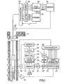
- a logging probe 11 is suspended at the end of a cable 12 in a borehole 13 which passes through formations 14.
- the probe 11 which has at its upper part a sealed envelope 15 containing electronic circuits is part of a logging device used for spectroscopy of natural gamma rays from formations 14.
- This device determines the T, U, K contents of thorium, uranium and potassium in the formations by spectral analysis of the natural radioactivity of the formations according to the principles described in the patent of United States of America US-A-3,967,878 already mentioned. However, this device is equipped with a new stabilization system.
- the stabilization of such a device is very important because it conditions the accuracy of the measurements.
- spectrum shifts are detected at several energy levels corresponding to peaks in the spectrum received, an error signal is calculated which is a function of these shifts and the response of the measuring device is stabilized by a loop. feedback which tends to cancel this error signal.
- At least one of the peaks is chosen from the gamma ray spectrum from the formations and can therefore decrease or even disappear during the measurement.
- the error signal is a function of the offsets which makes best use, for stabilization, of the gamma ray spectrum coming from the formations.
- an error signal X is produced which is a linear function of the form factors of several peaks.
- the A-weights are chosen to minimize the effect of statistical errors.
- these statistical errors could introduce inconsistencies in the stabilization, in particular when the amplitude of one of the detected peaks becomes very low, in which case the corresponding form factor F ;, near o / o no longer makes sense.
- the coefficients are determined so as to minimize the variance of X.
- Equations (2) and (4) give:
- the stabilization is carried out by means of two feedback loops, one of which uses two peaks of the gamma ray spectrum coming from the formations to produce an error signal.
- Figure 3 shows an example of a spectrum of natural gamma rays from formations. In this spectrum, there are several peaks, in particular a peak 16 at 1.46 MeV mainly due to the presence of potassium in the formations and a peak 17 at 2.61 MeV mainly due to the presence of thorium. In the embodiment described, these two peaks are used for a stabilization loop.
- the probe 11 conventionally contains a scintillation crystal 20, for example with sodium iodide, followed by a photomultiplier 21 to convert the received gamma rays into electrical pulses whose amplitude is proportional to the energy of gamma rays.
- These pulses are amplified by a linear amplifier 22 and then applied to a pulse height discriminator 23.
- the discriminator 23 comprises eleven comparators 24 whose reference thresholds are chosen as shown in Si to S "in FIG. 3. In the example chosen the thresholds If at S 11 are taken respectively equal to 200, 500, 1100, 1365, 1460, 1590, 2000, 2520, 2615, 2745 and 3000 KeV.
- Each comparator provides an output pulse only for a pulse of input whose amplitude is greater than the threshold of this comparator.
- the eleven outputs of the comparators are connected to logic selection circuits 25 or anti-coincidence circuits which draw the pulses comprised in nine different windows.
- Five windows W, at W 5 (see FIG. 3) are used for the actual measurements as indicated in the patent of United States of America US-A-3,976,878 already cited. These measurement windows are those between the thresholds (S 1 ⁇ S 2 ), (S 2 - S 3 ), (S 3 ⁇ S 5 ), (S 6 ⁇ S 7 ) and (S 7 ⁇ S 11 ).
- Four windows are used for stabilization.
- an anticoincidence logic circuit selects the pulses whose amplitude is between two thresholds.
- the pulses thus sorted by amplitudes into nine windows are applied to a transmission circuit 26 to be sent to the surface via the cable.
- These circuits 26 can be of the type described in French patent FR-A-2 374 694 (inventors A. Belaigues and others) for transmitting data or control words between the bottom and the surface.
- the pulses from the nine windows can be transmitted for example in the form of nine binary words each representing the number of pulses of a window for a duration of 16 milliseconds (1/60 sec.).
- the circuits 22 to 26 are placed in the sealed envelope 15.
- the information arriving at the surface is received by other transmission circuits 27 which apply the nine counting rates to an addition and memory circuit 28 which performs and stores the sum of the pulses in each window for an adjustable time t 1 to 4 seconds.
- the counting rates in the five measurement windows are applied to a processing circuit 30 which combines these counting rates to produce signals representative of the contents T, U, K in thorium, uranium and potassium of the formations, as explained in the patent. from the United States of America US-A-3,976,878 already mentioned.
- the processing circuit 30 also provides the total natural radioactivity GRtot by adding the counting rates of the five windows. These results are recorded by means of a magnetic recorder and also in graphic form on a film. The recording is carried out as a function of the depth detected by a wheel 32 in contact with the cable 12.
- the counting rates in the four stabilization windows are applied to a stabilization computer 33 which generates an error signal X according to equation (10).
- This error signal X is applied to the surface transmission circuits 27 which transmits it by the cable conductors to the bottom transmission circuits 26.
- this signal X is applied to a digital-analog converter 34 then to a filter 35 which can for example be an RC filter with a time constant of the order of 100 seconds so as to make the statistical variations negligible.
- the output of the filter 35 is connected to a subtraction circuit 36 which also receives a voltage from a reference supply 37 to vary this voltage in response to the error signal.
- the voltage thus controlled determines, via a voltage divider, the threshold values of the comparators 24.
- the circuit 36 is adapted to proportionally decrease the threshold values when the error signal X indicates a shift of the spectrum towards the bass. energies.
- the device may further comprise a second, fast-acting stabilization loop, which uses a second auxiliary source 40 of gamma rays.
- This source 40 disposed in the probe 11 is made of americium 241 with an emission peak centered on the value 60 KeV, that is to say below the spectrum detected of gamma rays coming from the formations.
- the gamma rays come from the second auxiliary source 40 gives at the output of the amplifier 22 electrical pulses applied to an amplifier 41 of ten gain.
- the output of the amplifier 41 is applied to a pulse height analyzer 42 formed by three comparators 43 and logic selection circuits 44.
- the comparators 43 whose threshold values come from a voltage divider supplied by the voltage reference 37 separate on three outputs the pulses whose amplitudes are respectively greater than three thresholds S 12 , S 13 and S 14 corresponding to gamma ray energies of 40, 60 and 80 KeV, that is to say below of the spectrum detected from the formations (see Figure 3).
- the logic of the selection circuits 44 has the function of sorting on two outputs on the one hand the pulses whose amplitude is between the two thresholds S 12 and S 13 and on the other hand those whose amplitude is between the two thresholds S, 3 and S 14 .
- the pulses of an americium peak are thus separated into two windows located on either side of the central energy 60 KeV.
- the two outputs of the logic 44 are respectively connected to the positive and negative inputs of an up-down counter 45 whose content is thus representative of the difference M Am- N Am of the counting rates of the pulses included in the two windows of the americium.
- the content of the up-down counter 45 is applied to a digital-analog converter 46 then to an integration circuit 47 which supplies an error signal to control the high voltage 48 of the photomultiplier.
- the error signal is applied so as to increase the gain of the photomultiplier when the americium peak shifts towards low energies, that is to say when the counting rate M Am of the lower window becomes higher than NAm in the upper window.
- Circuit 47 integrates the error signal with a time constant of a few seconds.
- the circuits 34 to 48 are arranged in the sealed casing 15.
- the second stabilization loop based on the americium peak and acting on the gain of the photomultiplier has the biggest and fastest corrective effect (a few seconds). This loop could also be designed so as to act on the gain of the amplifier 22 or on the reference voltage 37.
- the first stabilization loop, based on the potassium and thorium peaks, is of slower action (100 seconds for example) and refines the effect of the second. This gives an error on the measurement less than one percent.
- FIG. 2 represents in more detail a first embodiment, in the form of circuits, of the stabilization computer 33.
- This computer receives the counting rates during the time t M K , NK, MT and N, of the pulses in the two windows potassium and the two thorium windows.
- the counting rates N K and N T are applied to two complement circuits 50 and 51 which calculate the numbers -N K and -N T respectively .
- the output of circuit 50 is applied to an addition circuit 52 which also receives the count rate M K to provide signals representative of the difference (M K ⁇ N K ).
- Another addition circuit 53 receives the signals M K and N K to calculate the sum (M K + N K ). Corrections background noise are then carried out on the difference (M K -N K ) and the sum (M K + N K ) by means of two circuits 54 and 55.
- the coefficients a "a 2 and a 3 are determined in a calibration well by successively placing the device in front of several artificial formations of which we know the contents T, U, K. The difference in background noise is then subtracted from the difference in counting rates.
- circuit 55 we calculate the sum B s of the background noise in the two windows by the equation: in which the coefficients b 1 , b 2 and b 3 are determined as previously in a calibration well, and this sum B s is subtracted from the sum of the counting rates (M K + N K ).
- the corrected difference (M K- N K ) c is applied to a multiplication circuit 56 to be multiplied by the predetermined coefficient 1 / H K.
- this weighting coefficient depends on the window widths, the central energy of the peak and the resolution of the detector used (equation 3). In the example described, this coefficient 1 / H K is 24.58 for a detector whose resolution for cesium was 10%.
- the corrected sum (M K + N K ) c is applied to a multiplication circuit 57 to be multiplied by a coefficient equal to 1 / HK.
- the counting rate MT and the complement of the counting rate N T are applied to an addition circuit 62 which calculates the difference M T ⁇ N T.
- the two counting rates MT and N T are added in an addition circuit 63.
- the thorium peak has a background noise mainly due to uranium and it is possible to envisage corrections of background noise on the sum and the difference in counting rates, the same as for the potassium spike.
- this background noise is much lower than that of potassium, in the embodiment described, it has been chosen to apply the weights directly by the factors 1 / H T and 1 / HT by means of multiplication circuits 64 and 65 In the example, with the window widths chosen, the factor 1 / H T was taken equal to 31.51 for the same detector.
- the circuits 56 and 64 are connected to an addition circuit 66 which calculates the weighted sum ⁇ 1 of the different corrected for the counting rates:
- the circuits 57 and 65 are connected to an addition circuit 67 which calculates the weighted sum ⁇ 2 of the sums corrected for the counting rates:
- the output signals of circuits 66 and 67 are applied to a division circuit 70 which calculates the ratio ⁇ 1 / ⁇ 2 , that is to say the error signal X according to equation (10).
- the division circuit 70 mainly comprises a multiplier 71, a comparator 72 and an up-down counter 73.
- the number ⁇ 1 of the equation (14) and the output of the multiplier 71 are applied to the input of the comparator 72 whose outputs are applied to the up-down counter 73.
- comparator 72 has the effect of equalizing A and ⁇ 1 . Consequently, the output of the up-down counter 73 is indeed equal to the ratio:
- the multiplication circuits used can be of the MPY-12HJ type sold by the company TRW California, United States of America.
- this computer 33 can be a universal computer suitably programmed to supply the signal X.
- a general flow chart of the operations to be carried out is shown in FIG. 4. First of all, count rates M K are read. , N K , M T , N T and the contents T, U, K calculated (block 80). The counting rates for the background noise are then corrected by subtracting for example from each counting rate a number of counts calculated by a linear function of the contents T, U, K (block 81). The error signal X (block 82) is then calculated by equation (10) and this calculated value of the error signal is extracted to apply it to the transmission circuits 27. This calculation is carried out in real time for each depth level at which the probe 11 is located as represented by blocks 84 and 85. This embodiment is equivalent to that of FIG. 2.
- the contiguous detection windows are of unequal width. In the example these widths are 95 KeV for the lower window and 130 KeV for the upper window. We choose the larger upper window to take into account the decrease in detector resolution when the energy increases.
- the error signal can be calculated from a number of reference peaks greater than two, using the formula (10).
- the filtering carried out by the circuit 35 could be carried out by a program step added to the flow diagram of FIG. 4.
Landscapes
- Physics & Mathematics (AREA)
- Life Sciences & Earth Sciences (AREA)
- High Energy & Nuclear Physics (AREA)
- Spectroscopy & Molecular Physics (AREA)
- General Physics & Mathematics (AREA)
- Molecular Biology (AREA)
- Health & Medical Sciences (AREA)
- Environmental & Geological Engineering (AREA)
- Geology (AREA)
- General Life Sciences & Earth Sciences (AREA)
- Geophysics (AREA)
- Measurement Of Radiation (AREA)
- Credit Cards Or The Like (AREA)
- Geophysics And Detection Of Objects (AREA)
Applications Claiming Priority (2)
| Application Number | Priority Date | Filing Date | Title |
|---|---|---|---|
| FR8014066A FR2485752A1 (fr) | 1980-06-25 | 1980-06-25 | Procede et dispositif de mesure de rayons gamma dans un sondage |
| FR8014066 | 1980-06-25 |
Publications (3)
| Publication Number | Publication Date |
|---|---|
| EP0043313A2 EP0043313A2 (fr) | 1982-01-06 |
| EP0043313A3 EP0043313A3 (en) | 1982-01-13 |
| EP0043313B1 true EP0043313B1 (fr) | 1985-12-18 |
Family
ID=9243483
Family Applications (1)
| Application Number | Title | Priority Date | Filing Date |
|---|---|---|---|
| EP81400999A Expired EP0043313B1 (fr) | 1980-06-25 | 1981-06-22 | Procédé et dispositif de mesure de rayons gamma dans un sondage |
Country Status (9)
| Country | Link |
|---|---|
| US (1) | US4433240A (OSRAM) |
| EP (1) | EP0043313B1 (OSRAM) |
| JP (1) | JPS5739372A (OSRAM) |
| AU (1) | AU547451B2 (OSRAM) |
| BR (1) | BR8103928A (OSRAM) |
| CA (1) | CA1163379A (OSRAM) |
| DE (1) | DE3173241D1 (OSRAM) |
| FR (1) | FR2485752A1 (OSRAM) |
| NO (1) | NO154852C (OSRAM) |
Families Citing this family (35)
| Publication number | Priority date | Publication date | Assignee | Title |
|---|---|---|---|---|
| US4524273A (en) * | 1983-04-15 | 1985-06-18 | Dresser Industries, Inc. | Method and apparatus for gamma ray well logging |
| US4730263A (en) * | 1985-03-04 | 1988-03-08 | Gearhart Industries, Inc. | Method and device for measuring gamma radiation |
| US4668863A (en) * | 1985-04-10 | 1987-05-26 | Dresser Industries, Inc. | Neutron logging time spectral data acquisition system and method |
| AU582879B2 (en) * | 1985-07-22 | 1989-04-13 | Commonwealth Scientific And Industrial Research Organisation | A process for determining the degree of oxidation of material |
| US4883956A (en) * | 1985-12-23 | 1989-11-28 | Schlumberger Technology Corporation | Methods and apparatus for gamma-ray spectroscopy and like measurements |
| JPH065297B2 (ja) * | 1987-10-09 | 1994-01-19 | 浜松ホトニクス株式会社 | 核種弁別可能な線量計測装置 |
| AU636316B2 (en) * | 1988-11-28 | 1993-04-29 | Commonwealth Scientific And Industrial Research Organisation | Measurement of natural gamma-ray activity |
| US5023449A (en) * | 1989-08-30 | 1991-06-11 | Schlumberger Technology Corporation | Nuclear spectroscopy signal stabilization and calibration method and apparatus |
| US5053620A (en) * | 1989-12-13 | 1991-10-01 | Schlumberger Technology Corporation | Logging apparatus and method for determining concentrations of subsurface formation elements |
| US5171986A (en) * | 1991-09-27 | 1992-12-15 | Schlumberger Technology Corporation | Methods and apparatus for calibration of BGO scintillator gamma ray energy spectra |
| EP0562146A1 (fr) | 1992-03-27 | 1993-09-29 | Diasol Holding S.A. | Procédé et appareil de diagraphie d'un sondage géologique |
| US5475727A (en) * | 1993-07-09 | 1995-12-12 | Halliburton Company | Intelligent automatic gain stabilization for radiation detection instrument |
| RU2242031C2 (ru) * | 2002-11-12 | 2004-12-10 | Закрытое акционерное общество Научно-производственная фирма "СейсмоСет-Сервис" | Способ измерения интенсивности ядерного излучения в скважине |
| US7253401B2 (en) * | 2004-03-15 | 2007-08-07 | Weatherford Canada Partnership | Spectral gamma ray logging-while-drilling system |
| US7202456B2 (en) * | 2004-09-29 | 2007-04-10 | Precision Energy Services, Inc. | Gain stabilization apparatus and methods for spectral gamma ray measurement systems |
| US7482578B2 (en) * | 2006-06-12 | 2009-01-27 | Lonkar Services, Ltd. | Gamma radiation spectral logging system and method for processing gamma radiation spectra |
| US7800052B2 (en) * | 2006-11-30 | 2010-09-21 | Schlumberger Technology Corporation | Method and system for stabilizing gain of a photomultipler used with a radiation detector |
| US8400875B2 (en) | 2010-04-06 | 2013-03-19 | Raytheon Company | Active sonar system and active sonar method using a pulse sorting transform |
| WO2012158922A2 (en) | 2011-05-17 | 2012-11-22 | Schlumberger Canada Limited | System and method for gain regulation |
| GB2504771B (en) | 2012-08-10 | 2016-02-03 | Symetrica Ltd | Gamma-ray spectrometer |
| US8937275B2 (en) | 2012-10-12 | 2015-01-20 | Thermo Fisher Scientific Inc. | Method and apparatus to monitor gain of a proportional counter including correcting the counting threshold of a pulse height spectrum |
| US9933532B2 (en) * | 2013-12-04 | 2018-04-03 | Halliburton Energy Services, Inc. | Temperature correction of a gamma detector |
| US20150177409A1 (en) | 2013-12-20 | 2015-06-25 | Visuray Intech Ltd (Bvi) | Methods and Means for Creating Three-Dimensional Borehole Image Data |
| CA3054309A1 (en) | 2017-02-24 | 2018-08-30 | Philip Teague | Improving resolution of detection of an azimuthal distribution of materials in multi-casing wellbore environments |
| AU2018225203B2 (en) | 2017-02-27 | 2021-07-01 | Alex Stewart | Detecting anomalies in annular materials of single and dual casing string environments |
| EP4550008A3 (en) | 2017-10-17 | 2025-07-02 | Philip Teague | Methods and means for simultaneous casing integrity evaluation and cement inspection in a multiple-casing wellbore environment |
| US20190048709A1 (en) | 2017-10-18 | 2019-02-14 | Philip Teague | Methods and means for casing, perforation and sand-screen evaluation using backscattered x-ray radiation in a wellbore environment |
| WO2019079732A1 (en) | 2017-10-19 | 2019-04-25 | Philip Teague | METHODS AND MEANS FOR ASSESSING TUBING INTEGRITY USING RETROFILE X-RAY RADIATION IN A WELLBORE ENVIRONMENT |
| EP3701294A1 (en) | 2017-10-23 | 2020-09-02 | Philip Teague | Methods and means for determining the existence of cement debonding within a cased borehole using x-ray techniques |
| WO2019103939A1 (en) | 2017-11-22 | 2019-05-31 | Mauro Arrambide | Methods and means for fracture mapping in a well bore |
| US20190195813A1 (en) | 2018-03-01 | 2019-06-27 | Philip Teague | Methods and Means for the Measurement of Tubing, Casing, Perforation and Sand-Screen Imaging Using Backscattered X-ray Radiation in a Wellbore Environment |
| CA3099022C (en) | 2018-05-03 | 2023-02-28 | Philip Teague | Methods and means for evaluating and monitoring formation creep and shale barriers using ionizing radiation |
| EP3794383A1 (en) | 2018-05-18 | 2021-03-24 | Philip Teague | Methods and means for measuring multiple casing wall thicknesses using x-ray radiation in a wellbore environment |
| CN112649888B (zh) * | 2020-11-24 | 2022-08-12 | 东华理工大学 | 一种基于能谱测井特征谱峰的铀矿定量刻度系数求法 |
| WO2024030160A1 (en) | 2022-08-03 | 2024-02-08 | Visuray Intech Ltd (Bvi) | Methods and means for the measurement of tubing, casing, perforation and sand-screen imaging using backscattered x-ray radiation in a wellbore environment |
Citations (4)
| Publication number | Priority date | Publication date | Assignee | Title |
|---|---|---|---|---|
| US3101409A (en) * | 1962-05-03 | 1963-08-20 | Lloyd E Fite | Drift control in an analytical gamma ray spectrometer |
| US3829686A (en) * | 1971-09-20 | 1974-08-13 | Texaco Inc | Pulsed neutron logging system with gain compensation |
| US3976878A (en) * | 1973-10-01 | 1976-08-24 | Schlumberger Technology Corporation | Natural gamma ray spectrum analysis technique |
| FR2379694A1 (fr) * | 1977-02-03 | 1978-09-01 | Schlumberger Prospection | Systeme de transmission de donnees pour puits de forage |
Family Cites Families (7)
| Publication number | Priority date | Publication date | Assignee | Title |
|---|---|---|---|---|
| CH410205A (de) * | 1964-06-04 | 1966-03-31 | Foerderung Forschung Gmbh | Verfahren zur Stabilisierung der Verstärkung von Scintillationsspektrometern |
| FR2077483A1 (en) * | 1970-01-20 | 1971-10-29 | Inst Francais Du Petrole | Gamma radiation spectroscopy - using a reference source to stabilise readings in geological surveying |
| GB1384099A (en) * | 1971-09-20 | 1975-02-19 | Texaco Development Corp | Pulsed neutron logging system with gain compensation |
| US3767921A (en) * | 1972-03-31 | 1973-10-23 | Texaco Inc | Well logging system with linearity control |
| FR2211664B1 (OSRAM) * | 1972-12-21 | 1976-08-27 | Schlumberger Prospection | |
| JPS5045701A (OSRAM) * | 1973-08-29 | 1975-04-24 | ||
| AU500341B2 (en) * | 1975-03-31 | 1979-05-17 | Schlumberger Technology B.V. | Neutron/gamma ray prospecting |
-
1980
- 1980-06-25 FR FR8014066A patent/FR2485752A1/fr active Granted
-
1981
- 1981-06-04 US US06/270,670 patent/US4433240A/en not_active Expired - Fee Related
- 1981-06-15 NO NO812015A patent/NO154852C/no unknown
- 1981-06-17 AU AU71902/81A patent/AU547451B2/en not_active Ceased
- 1981-06-22 EP EP81400999A patent/EP0043313B1/fr not_active Expired
- 1981-06-22 BR BR8103928A patent/BR8103928A/pt unknown
- 1981-06-22 DE DE8181400999T patent/DE3173241D1/de not_active Expired
- 1981-06-24 CA CA000380483A patent/CA1163379A/en not_active Expired
- 1981-06-25 JP JP56099043A patent/JPS5739372A/ja active Pending
Patent Citations (4)
| Publication number | Priority date | Publication date | Assignee | Title |
|---|---|---|---|---|
| US3101409A (en) * | 1962-05-03 | 1963-08-20 | Lloyd E Fite | Drift control in an analytical gamma ray spectrometer |
| US3829686A (en) * | 1971-09-20 | 1974-08-13 | Texaco Inc | Pulsed neutron logging system with gain compensation |
| US3976878A (en) * | 1973-10-01 | 1976-08-24 | Schlumberger Technology Corporation | Natural gamma ray spectrum analysis technique |
| FR2379694A1 (fr) * | 1977-02-03 | 1978-09-01 | Schlumberger Prospection | Systeme de transmission de donnees pour puits de forage |
Also Published As
| Publication number | Publication date |
|---|---|
| CA1163379A (en) | 1984-03-06 |
| BR8103928A (pt) | 1982-03-09 |
| DE3173241D1 (en) | 1986-01-30 |
| US4433240A (en) | 1984-02-21 |
| NO154852B (no) | 1986-09-22 |
| NO812015L (no) | 1981-12-28 |
| EP0043313A3 (en) | 1982-01-13 |
| EP0043313A2 (fr) | 1982-01-06 |
| FR2485752A1 (fr) | 1981-12-31 |
| JPS5739372A (en) | 1982-03-04 |
| FR2485752B1 (OSRAM) | 1984-04-20 |
| AU547451B2 (en) | 1985-10-24 |
| AU7190281A (en) | 1982-01-07 |
| NO154852C (no) | 1987-01-07 |
Similar Documents
| Publication | Publication Date | Title |
|---|---|---|
| EP0043313B1 (fr) | Procédé et dispositif de mesure de rayons gamma dans un sondage | |
| FR2513387A1 (fr) | Procede et dispositif de diagraphie nucleaire pour determiner une caracteristique corrigee des formations | |
| US11119226B2 (en) | Spectral gamma ray downhole logging tool | |
| CH631551A5 (fr) | Procede et dispositif de determination du taux de coincidences fortuites dans un compteur a scintillation utilisant la technique de comptage par coincidence. | |
| FR2658616A1 (fr) | Procede et dispositif pour l'evaluation de la cimentation dans un puits et ciment utilisable pour un tel procede. | |
| Mahagammulla Gamage et al. | Retrieval of temperature from a multiple channel pure rotational Raman backscatter lidar using an optimal estimation method | |
| JPH05134043A (ja) | デコンボルーシヨンフイルタをもつ原子核検出装置 | |
| EP0202980A1 (fr) | Système pour détecter la présence d'un signal pur dans un signal bruité discret mesuré à taux moyen de bruit constant avec une probabilité de fausse détection inférieure à un taux de fausse détection prédéterminé | |
| FR2578329A1 (fr) | Procede et appareil de mesure de rayonnement gamma. | |
| US4542292A (en) | Correction of natural gamma radiation logs for the effects of gamma ray emission from and attenuation by the borehole fluid | |
| EP0414587A1 (fr) | Procédé et chaîne de spectrométrie gamma | |
| FR2579770A1 (fr) | Systeme de diagraphie gamma spectrometrique pour la determination des parametres geologiques d'une roche | |
| FR3088445A1 (fr) | Procede d'evaluation de la concentration massique en uranium d'un echantillon par spectrometrie gamma et dispositif associe | |
| EP2726815B1 (fr) | Procede et dispositif d'identification d'un materiau par analyse spectrale de rayonnements electromagnetiques traversant ce materiau | |
| EP3617751B1 (fr) | Procédé d'auto-calibration d'un dispositif de détection de rayonnements ionisants | |
| EP0200596B1 (fr) | Système de suppression du bruit et de ses variations pour la détection d'un signal pur dans signal discret bruité mesuré | |
| WO2023203247A1 (fr) | Dispositif et procede de caracterisation d' une profondeur d' activite d' un radionucleide dans un milieu solide | |
| KR20230041175A (ko) | 핵종판별을 위한 방사선 스펙트럼의 온도보상방법 | |
| EP0452395B1 (fr) | Systeme pour detecter la presence d'un signal pur dans un signal bruite discret mesure a taux moyen de bruit constant | |
| EP1256018A1 (fr) | Ensemble et procede de mesure de rayonnement ionisant avec correction de bruit de fond | |
| FR2790835A1 (fr) | Procede et appareil pour etalonner les indications d'un outil de fond de puits | |
| FR3128017A1 (fr) | Dispositif d’évaluation en forage d’une teneur en uranium et d’une porosité hydrogène d’une région d’intérêt d’une formation géologique et procédé associé | |
| FR2481811A1 (fr) | Procede de traitement de donnees de diagraphie | |
| WO2023031465A1 (fr) | Procédé d'évaluation de la teneur en uranium par spectrométrie gamma dans un forage et dispositif associé | |
| Coburn et al. | Polarization Measurements of GRBs with RHESSI |
Legal Events
| Date | Code | Title | Description |
|---|---|---|---|
| PUAI | Public reference made under article 153(3) epc to a published international application that has entered the european phase |
Free format text: ORIGINAL CODE: 0009012 |
|
| PUAL | Search report despatched |
Free format text: ORIGINAL CODE: 0009013 |
|
| AK | Designated contracting states |
Designated state(s): DE FR GB IT NL |
|
| AK | Designated contracting states |
Designated state(s): DE FR GB IT NL |
|
| 17P | Request for examination filed |
Effective date: 19820422 |
|
| GRAA | (expected) grant |
Free format text: ORIGINAL CODE: 0009210 |
|
| ITF | It: translation for a ep patent filed | ||
| AK | Designated contracting states |
Designated state(s): DE FR GB IT NL |
|
| REF | Corresponds to: |
Ref document number: 3173241 Country of ref document: DE Date of ref document: 19860130 |
|
| PLBE | No opposition filed within time limit |
Free format text: ORIGINAL CODE: 0009261 |
|
| STAA | Information on the status of an ep patent application or granted ep patent |
Free format text: STATUS: NO OPPOSITION FILED WITHIN TIME LIMIT |
|
| 26N | No opposition filed | ||
| ITTA | It: last paid annual fee | ||
| PGFP | Annual fee paid to national office [announced via postgrant information from national office to epo] |
Ref country code: DE Payment date: 19920820 Year of fee payment: 12 |
|
| PGFP | Annual fee paid to national office [announced via postgrant information from national office to epo] |
Ref country code: NL Payment date: 19930630 Year of fee payment: 13 |
|
| PG25 | Lapsed in a contracting state [announced via postgrant information from national office to epo] |
Ref country code: DE Effective date: 19940301 |
|
| PG25 | Lapsed in a contracting state [announced via postgrant information from national office to epo] |
Ref country code: NL Effective date: 19950101 |
|
| NLV4 | Nl: lapsed or anulled due to non-payment of the annual fee | ||
| PGFP | Annual fee paid to national office [announced via postgrant information from national office to epo] |
Ref country code: FR Payment date: 19950419 Year of fee payment: 15 |
|
| PGFP | Annual fee paid to national office [announced via postgrant information from national office to epo] |
Ref country code: GB Payment date: 19960401 Year of fee payment: 16 |
|
| PG25 | Lapsed in a contracting state [announced via postgrant information from national office to epo] |
Ref country code: FR Effective date: 19970228 |
|
| REG | Reference to a national code |
Ref country code: FR Ref legal event code: ST |
|
| PG25 | Lapsed in a contracting state [announced via postgrant information from national office to epo] |
Ref country code: GB Free format text: LAPSE BECAUSE OF NON-PAYMENT OF DUE FEES Effective date: 19970622 |
|
| GBPC | Gb: european patent ceased through non-payment of renewal fee |
Effective date: 19970622 |