EP0043275A1 - Serial impact printer having two printing modes - Google Patents
Serial impact printer having two printing modes Download PDFInfo
- Publication number
- EP0043275A1 EP0043275A1 EP81302951A EP81302951A EP0043275A1 EP 0043275 A1 EP0043275 A1 EP 0043275A1 EP 81302951 A EP81302951 A EP 81302951A EP 81302951 A EP81302951 A EP 81302951A EP 0043275 A1 EP0043275 A1 EP 0043275A1
- Authority
- EP
- European Patent Office
- Prior art keywords
- character
- wires
- printing
- dot
- impact printer
- Prior art date
- Legal status (The legal status is an assumption and is not a legal conclusion. Google has not performed a legal analysis and makes no representation as to the accuracy of the status listed.)
- Granted
Links
Images


Classifications
-
- B—PERFORMING OPERATIONS; TRANSPORTING
- B41—PRINTING; LINING MACHINES; TYPEWRITERS; STAMPS
- B41J—TYPEWRITERS; SELECTIVE PRINTING MECHANISMS, i.e. MECHANISMS PRINTING OTHERWISE THAN FROM A FORME; CORRECTION OF TYPOGRAPHICAL ERRORS
- B41J3/00—Typewriters or selective printing or marking mechanisms characterised by the purpose for which they are constructed
- B41J3/54—Typewriters or selective printing or marking mechanisms characterised by the purpose for which they are constructed with two or more sets of type or printing elements
- B41J3/546—Combination of different types, e.g. using a thermal transfer head and an inkjet print head
-
- B—PERFORMING OPERATIONS; TRANSPORTING
- B41—PRINTING; LINING MACHINES; TYPEWRITERS; STAMPS
- B41J—TYPEWRITERS; SELECTIVE PRINTING MECHANISMS, i.e. MECHANISMS PRINTING OTHERWISE THAN FROM A FORME; CORRECTION OF TYPOGRAPHICAL ERRORS
- B41J1/00—Typewriters or selective printing mechanisms characterised by the mounting, arrangement or disposition of the types or dies
- B41J1/60—Typewriters or selective printing mechanisms characterised by the mounting, arrangement or disposition of the types or dies with types or dies on spherical, truncated-spherical, or like surfaces
-
- B—PERFORMING OPERATIONS; TRANSPORTING
- B41—PRINTING; LINING MACHINES; TYPEWRITERS; STAMPS
- B41J—TYPEWRITERS; SELECTIVE PRINTING MECHANISMS, i.e. MECHANISMS PRINTING OTHERWISE THAN FROM A FORME; CORRECTION OF TYPOGRAPHICAL ERRORS
- B41J2/00—Typewriters or selective printing mechanisms characterised by the printing or marking process for which they are designed
- B41J2/22—Typewriters or selective printing mechanisms characterised by the printing or marking process for which they are designed characterised by selective application of impact or pressure on a printing material or impression-transfer material
- B41J2/23—Typewriters or selective printing mechanisms characterised by the printing or marking process for which they are designed characterised by selective application of impact or pressure on a printing material or impression-transfer material using print wires
- B41J2/235—Print head assemblies
- B41J2/24—Print head assemblies serial printer type
Definitions
- This invention relates to a serial impact printer, and more particularly to a serial impact printer having two printing modes.
- Impact printers are useful in their multiple copy capability and their flexibility with regard to print receiving paper, compared with non-impact printers such as ink-jet printers and thermal printers.
- Impact printers are classified according to their printing mode into two types, one being a formed-character printing type for printing fully formed characters on print receiving paper on a platen, and the other being a dot-matrix type for impacting the print receiving paper on the platen by selected ones of a plurality of wires.
- These types of impact printers have different features in use.
- the formed-character printing type is excellent in print quality compared with the dot-matrix type, while the latter is advantageous in printing speed. Therefore, these types of impact printers are separately used in accordance with printing purposes. This requires at least two impact printers in order to respond to all kinds of printing requirements.
- a multi-head serial printer in which two types of printing heads, i.e., a formed-character printing head and a dot-matrix printing head are mounted on a single carriage, and one of two printing heads is selectively used for printing in accordance with the printing purpose.
- the multi-head serial printer because the two printing heads are mounted at different positions on the carriage, printing strokes for such printing heads are spaced apart from each other by a distance equal to an interval between the two printing heads. This means that the two printing heads have different left or right margins.
- two printing heads on the single carriage make the carriage massive, whereby a complicated position- control circuit is required for positioning the massive carriage at a commanded position.
- a serial impact printer for serially printing on a print receiving member, the said printer comprising: a carriage arranged for sliding along a print receiving member; a character carrying member rotatably mounted upon said carriage and having a plurality of fingers, at least one formed-character being disposed on a finger; a plurality of wires mounted on said carriage and behind said character carrying member with respect to said print receiving member; and actuator means for actuating said plurality of wires.
- a formed character printing mode printing is achieved by impacting a selected character on the character carrying member by means of at least one of the plurality of wires.
- a dot-matrix printing mode the printing is performed by directly impacting the paper by means of selected ones of the plurality of wires.
- the first embodiment shown comprises a platen 2 on which a print receiving member (paper) 1 is arranged, a carriage 3 for sliding along the platen 2, and a tractor unit 4 for feeding the paper 1.
- the platen 2 is driven by a pulse motor 5 through a motor gear 6 directly coupled to the pulse motor 5, an idle gear 7 and a platen gear 8 directly coupled to the platen 2.
- the platen 2 may be manually driven by means of a knob 15.
- the tractor unit 4 is driven in synchronism with the rotation of the platen 2.
- the rotational power of the platen 2 is transmitted from a platen gear 9 directly coupled to the platen 2 through an idle gear 10 to a tractor gear 11 directly coupled to the tractor unit 4.
- the tractor unit 4 is arranged to feed the paper 1 via tractor pins 50 by a predetermined interval.
- the carriage 3 includes a print thimble 12, a dot-matrix print head 13, having a plurality of wires 53 (Fig. 4), and an inked ribbon cartridge 14.
- the carriage 3 is supported on a guide shaft 17 by means of a guide bearing 16.
- the carriage 3 is driven to slide along the platen 2 by means of a spacing motor 18 via a cable 19 constituted by two parts 19a and 19b.
- the motor 18 has ashaft, upon one end of which there is mounted a driving pulley 20 in which there are a number of grooves for driving the cable 19 which is coupled to the carriage 3, the cable being guided by guide pulleys 21 (21a and 21b) and 22 (22a and 22b) mounted on a frame, guide pulleys 23 (23a and 23b) mounted on the carriage 3, and guide pulleys 24 (24a and 24b) mounted on the frame.
- the carriage 3 comprises a front casting 25 on which various mechanisms. are mounted.
- a motor 26 for rotating the print thimble 12
- a motor 28 for moving the print thimble 12 up and down, i.e. vertically, to select one of characters on a finger of the print thimble 12.
- a torque piece 29 is coupled to a shaft of the motor 26 by a screw 30.
- a vertical slide sleeve 31 coupled to the torque piece 29 is installed for movement slidably up and down, i.e. vertical, on the shaft of the motor 26.
- a spring 32 (Fig. 3) urges the print thimble 12 away from the torque piece 29.
- a torque disc 33 On the vertical slide sleeve 31 there is provided a torque disc 33, On a pin 35 situated on a shaft of the torque disc 33, a lock piece 34 is arranged for securing the print thimble 12 thereto.
- the vertical slide sleeve 31 has a groove to which there is coupled a roller 37 provided on a drive cam follower 36.
- the drive cam follower 36 is coupled to the motor 28 so that the vertical slide sleeve 31 may be positioned at any vertical (up and down) position in response to a rotational angle of the motor 28.
- a card holder bracket 39 On the front casting 25 there is provided a card holder bracket 39 on which a card holder 43 is mounted.
- the holder 43 serves to keep the paper 1 in contact with the platen 2.
- an arm member 39' is mounted for guiding an inked ribbon 38 pulled out of the cartridge 14.
- An inked-ribbon base 40 is provided on a bracket (not shown) secured to the front casting 25.
- the inked ribbon cartridge 14 is supported on the base 40 by means of a member 40" in such a way that it can easily be changed.
- a ribbon feed motor 41 is mounted on the base 40.
- the inked ribbon 38 in the cartridge 14 is caused to be fed by the motor 41 acting through a worm gear 41 , coupled to the drive shaft of the motor 41, and a gear 42' coupled to a torque shaft 42, which is coupled to a feed shaft 14' of the cartridge 14.
- a guide casting 45 On the front casting 25 there is provided a guide casting 45, on which guide bearings 16a, 16b and 16c are mounted at an angle so as to slide on a guide shaft 17a. Similarly, guide bearings 16d and 16e are provided on the front casting 25 and are slidably supported on a guide shaft 17b.
- the print thimble 12 includes a number of fingers 46, on each of which two formed characters 47 are disposed,as shown in Fig. 2.
- the print thimble 12 has a centre hole into which the shaft of a torque disc 33 is to be inserted and to which it can be secured by means of a locking piece 34. The print thimble 12 may be removed by unlocking the lock piece 34.
- the dot-matrix head 13 is arranged behind a finger 46 with respect to the platen 2, i.e., within an area surrounded by the fingers 46 of the print thimble 12, so that the selected character on a finger 46 is impacted by at least one of wires 53 when operating in the formed-character printing mode.
- the dot-matrix head 13 is used not only as the dot-matrix printing head itself in the dot-matrix printing mode, but also as hammer means for impacting the rear of the selected character on the finger 46, when operating in the formed-character printing mode.
- the dot-matrix head 13 when electromagnet 51 is actuated, an armature 52 is energised to move a wire 53 contacting with the armature 52 towards the platen 2.
- the wire 53 is returned to the home position by means of a wire reset spring 54 and an armature reset spring 55.
- the dot-matrix head shown in Fig.4 has only two sets of wire assemblies, each including a wire 53, the magnet 51, the armature 52, the wire reset spring 54 and the armature reset spring 55
- the practical dot-matrix head has a larger number of wire assemblies, e.g. seven assemblies, with the ends of the wires being linearly arranged as shown in Fig. 11.
- the print thimble 12 is mechanically moved in both the rotational and vertical(i.e. linear) directions by the motors 26 and 28, respectively.
- the dot-matrix head 13 is actuated to impact the selected character by means of a plurality of wires 53, whereby the selected character is impacted through the inked ribbon 38 and the paper 1 to the platen 2 for printing the selected character on the paper 1.
- the print thimble 12 is removed by unlocking the locking piece 34.
- a plurality of wire assemblies are actuated in accordance with a command signal representing a character, a letter, a symbol, or a graphic pattern as in a conventional dot-matrix printer, whereby the ink in the ribbon 38 is printed in a dotted form on the paper 1.
- the dotted printing is repeated while the carriage 3 is slid by the motor 18 relative to the paper and/or the paper 1 is fed by the tractor unit 4.
- the'print thimble 12 is moved in the so-called vertical direction and can be positioned at three steps, i.e., at an upper position, a middle position, and a lower position, as shown in Figs. 5A, 5B, and 5C, respectively, in accordance with the rotational angle of the motor 28.
- the upper or middle position on each finger 46 is selected by rotating the motor 28.
- the vertical slide sleeve 31 is positioned at an upper position, i.e., the print thimble 12 is set at the upper position, as shown in Fig. 5A.
- the sleeve 31 is displaced to a middle position, i.e., the print thimble 12 is positioned at the middle position, as shown in Fig. 5B.
- the vertical slide sleeve 31 is displaced to a lower position so that the selected wires of the head 13 do not impact a finger 46 of the print thimble 12, but can impact directly on to the paper 1 on the platen 2, when the selected wire assemblies are actuated in accordance with the command signal.
- the dot-matrix printing can be achieved as in the conventional dot-matrix printer.
- the print thimble 12' used in the third embodiment has fingers 46 whose end portions are cut-off, as indicated at 48.
- Each of the fingers 46 having a portion cut-off at 48 has one formed-character thereon.
- the formed-character printing is achieved as in the conventional printer except that the wires in the dot-matrix head 13 are used instead of the normal hammer means.
- the motor 26 is controlled so that the space which exists in place of the portion cut off at 48 is positioned at a position facing with the platen 2.
- the selected wires of the head 13 do not impact the finger 46, but are able to impact directly to the paper 1 on the platen 2 through the space created in place of the cut-off portion 48 when the selected wire assemblies are actuated.
- Dot-matrix printing is thus able to be carried out as in the conventional dot-matrix printer.
- the fourth embodiment further comprises adjusting frame means installed on the two side frames of the printer for changing the distance between the platen 2 installed thereon and the carriage 3.
- the adjusting frames 60a and 60b are slidably supported on guide pins 63 by inserting the pins 63 into elongated holes 63'.
- Eccentric blocks 61a and 61b are secured to the shaft 65 rotatably supported on the side frames 59a and 59b and inserted into guide holes 67 of the adjusting frames.
- a gear 68 secured to the shaft 65 is coupled to motor gear 69 by means of a belt 70, whereby the positions of the adjusting frames 60a and 60b are changeable by rotating the eccentric blocks 61a and 61b by means of a pulse motor 62.
- Springs 64a and 64b are used for preventing any loosening between the guide holes 67a and 67b, and the eccentric blocks 61a and 61b.
- the platen 2 is secured to clamp plates 72a and 72b mounted on the adjusting frames 60a and 60b by screws 71a and 71b.
- the distance between the platen 2, i.e. the paper 1 and the carriage 3 is adjusted in response to the printing mode by moving the adjusting frames 60a, 60b, on which the platen 2 is mounted, by means of the pulse motor 62.
- the distance is greater than in the dot-matrix printing mode by a value substantially equal to the thickness of the finger 46 of the print thimble 12.
- the adjustment of the distance between the platen 2 and the carriage 3, i.e. according to the thickness of the paper 1, may be made manually, as shown in Fig. 9, by moving a lever 71 pivotted about an axis 80 and contacting with a spring detent 72.
- the print thimble 12 is moved in the vertical direction, as in the second embodiment shown in Fig. 5. Further, the dot-matrix head 13 is moved in the lateral direction for adjusting the distance from the platen 2 in response to the selected printing mode.
- the dot-matrix head 13 is secured to a head holder 65 by screws.
- Guide pins 64a and support pins are provided on both sides of the holder 65.
- the guide pins 64a are inserted in elongated holes 59 on the front casting 25.
- the support pins are rotatably coupled to one end of a guide hole of each of the arms 61a pivotted in the axis of the front casting 25.
- the distance between the platen 2 and head 13 can be changed by moving the arms 61a.
- Arm springs 63a apply power to the arms 61a in a direction so as to keep away the head 13 from the platen 2.
- Levers 67a are rotatably supported upon the front casting 25 with one end being coupled to the vertical slide sleeve 31 through bearings 69a and the other end having bearings 71a.
- the bearings 71a push on the lower portions of the levers 61a to shift the head 13 towards the platen 2, when the sleeve 31 is positioned at the lower position in the dot-matrix printing mode, as shown in Fig. 10B.
- the number of wires to be actuated may depend upon the character to be printed. In other words, the number of wires to be actuated is changed in response to the surface dimensions of the characters to be printed so as to keep the print pressure on the paper substantially constant.
- the wires are selected in response to the character to be printed, i.e., with the relationship shown in the table of Fig.12.
- the wire selection circuit comprises a character decoder 91 for producing pulses at output lines in accordance with the table of Fig. 12, a pulse generator 92 receiving a hammer strobe pulse, AND gates 93 for AND-gating the pulses from the decoder circuit 91 with the pulse generator 92, and amplifiers 94.
- the outputs from the amplifiers 94 are supplied to electromagnets 51a to 51g corresponding to wires 53a to 53g, whereby the selected wire assemblies in accordance with the table of Fig. 12 are actuated.
- the wires to be actuated in the formed-character printing mode may be selected in accordance with the shape of a character to be printed. For example, when the numeral "8" is to be printed in the formed-character printing mode, the wires shown by black circles in Fig. 14B are selected. Further, in case of printing the symbol ", the wires shown by black circlesin Fig. 14C are selected.
- the wires of the dot-matrix head are used as hammer means impacting the selected character in the formed-character printing mode. It may be replaced by a composite head 100, as shown in Fig. 15, having a plurality of wires 101 for printing in the dot-matrix printing mode and a hammer 102 for impacting the selected character in the formed-character printing mode.
- the petal-type print thimble 12 used as character carrying means in the above embodiments may be replaced by a daisy wheel having a number of fingers arranged radially.
Abstract
Description
- This invention relates to a serial impact printer, and more particularly to a serial impact printer having two printing modes.
- Impact printers are useful in their multiple copy capability and their flexibility with regard to print receiving paper, compared with non-impact printers such as ink-jet printers and thermal printers. Impact printers are classified according to their printing mode into two types, one being a formed-character printing type for printing fully formed characters on print receiving paper on a platen, and the other being a dot-matrix type for impacting the print receiving paper on the platen by selected ones of a plurality of wires. These types of impact printers have different features in use. The formed-character printing type is excellent in print quality compared with the dot-matrix type, while the latter is advantageous in printing speed. Therefore, these types of impact printers are separately used in accordance with printing purposes. This requires at least two impact printers in order to respond to all kinds of printing requirements.
- For this purpose, there has been proposed, as disclosed in the Japanese Patent Disclosure NO.54-156725, a multi-head serial printer in which two types of printing heads, i.e., a formed-character printing head and a dot-matrix printing head are mounted on a single carriage, and one of two printing heads is selectively used for printing in accordance with the printing purpose. In the multi-head serial printer, because the two printing heads are mounted at different positions on the carriage, printing strokes for such printing heads are spaced apart from each other by a distance equal to an interval between the two printing heads. This means that the two printing heads have different left or right margins. Further, two printing heads on the single carriage make the carriage massive, whereby a complicated position- control circuit is required for positioning the massive carriage at a commanded position.
- It is, therefore, an object of this invention to provide a serial impact printer capable of providing two printing modes and having a simplified printing-carriage mechansim.
- It is another object of this invention to provide a serial impact printer, in which the printing operations associated with two printing modes can be selectively performed by means of a single printing head.
- According to this invention, there is provided a serial impact printer for serially printing on a print receiving member, the said printer comprising: a carriage arranged for sliding along a print receiving member; a character carrying member rotatably mounted upon said carriage and having a plurality of fingers, at least one formed-character being disposed on a finger; a plurality of wires mounted on said carriage and behind said character carrying member with respect to said print receiving member; and actuator means for actuating said plurality of wires. In a formed character printing mode , printing is achieved by impacting a selected character on the character carrying member by means of at least one of the plurality of wires. In a dot-matrix printing mode, the printing is performed by directly impacting the paper by means of selected ones of the plurality of wires.
- The above and other features and advantages of this invention will be apparent from the following description of preferred embodiments of this invention taken in conjunction with the accompanying drawings, wherein :
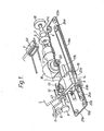
- Fig. 1 is a perspective view of a first embodiment of this invention;
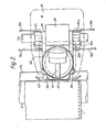
- Fig. 2 is a plan view of the carriage shown in Fig. 1;
- Fig. 3 is a side view of the carriage shown in Fig. 1;
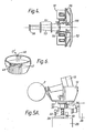
- Fig. 4 is a cross-sectional view of the dot-matrix head mounted on the carriage shown in Fig. 1;
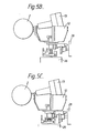
- Figs 5A, 5B and 5C are side views of a carriage illustrating the positional relationship between a print thimble and a dot-matrix head for use in a second embodiment of this invention;
- Fig. 6 is a perspective view of a print thimble for use in a third embodiment of this invention;
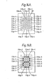
- Fig. 7 is a plan view of distance adjusting means for use in a fourth embodiment of this invention;
- Fig. 8 is a side view of the distance adjusting means shown in Fig. 7;
- Fig. 9 is a side view of another embodiment of distance adjusting means;
- Figs. 10A and 10B are side views of a printer head for use in a fifth embodiment of this invention;
- Fig. 11 is an end view illustrating an arrangement of the end portions of the wires of a dot-matrix head;
- Fig. 12 is a chart showing the relationship between the character to be printed and the selected wires;
- Fig. 13 is a block diagram of wire selection circuit;
- Figs 14A, 14B and 14C are end views illustrating arrangements of the end portions of another example of dot-matrix head; and
- Figs. 15A and 15B show a modified dot-matrix head.
- Referring to Fig. 1, the first embodiment shown comprises a
platen 2 on which a print receiving member (paper) 1 is arranged, acarriage 3 for sliding along theplaten 2, and atractor unit 4 for feeding thepaper 1. Theplaten 2 is driven by apulse motor 5 through a motor gear 6 directly coupled to thepulse motor 5, anidle gear 7 and aplaten gear 8 directly coupled to theplaten 2. Theplaten 2 may be manually driven by means of aknob 15. - The
tractor unit 4 is driven in synchronism with the rotation of theplaten 2. The rotational power of theplaten 2 is transmitted from a platen gear 9 directly coupled to theplaten 2 through anidle gear 10 to a tractor gear 11 directly coupled to thetractor unit 4. Thetractor unit 4 is arranged to feed thepaper 1 viatractor pins 50 by a predetermined interval. - The
carriage 3 includes aprint thimble 12, a dot-matrix print head 13, having a plurality of wires 53 (Fig. 4), and an inkedribbon cartridge 14. Thecarriage 3 is supported on a guide shaft 17 by means of a guide bearing 16. Thecarriage 3 is driven to slide along theplaten 2 by means of aspacing motor 18 via a cable 19 constituted by twoparts motor 18 has ashaft, upon one end of which there is mounted adriving pulley 20 in which there are a number of grooves for driving the cable 19 which is coupled to thecarriage 3, the cable being guided by guide pulleys 21 (21a and 21b) and 22 (22a and 22b) mounted on a frame, guide pulleys 23 (23a and 23b) mounted on thecarriage 3, and guide pulleys 24 (24a and 24b) mounted on the frame. - Referring to Figs. 2 and 3, the
carriage 3 comprises afront casting 25 on which various mechanisms. are mounted. There is provided on the front casting 25 amotor 26 for rotating theprint thimble 12, and amotor 28 for moving the print thimble 12 up and down, i.e. vertically, to select one of characters on a finger of theprint thimble 12. For character selection, atorque piece 29 is coupled to a shaft of themotor 26 by ascrew 30. Avertical slide sleeve 31 coupled to thetorque piece 29 is installed for movement slidably up and down, i.e. vertical, on the shaft of themotor 26. A spring 32 (Fig. 3) urges theprint thimble 12 away from thetorque piece 29. On thevertical slide sleeve 31 there is provided atorque disc 33, On apin 35 situated on a shaft of thetorque disc 33, alock piece 34 is arranged for securing theprint thimble 12 thereto. Thevertical slide sleeve 31 has a groove to which there is coupled a roller 37 provided on adrive cam follower 36. Thedrive cam follower 36 is coupled to themotor 28 so that thevertical slide sleeve 31 may be positioned at any vertical (up and down) position in response to a rotational angle of themotor 28. - On the
front casting 25 there is provided acard holder bracket 39 on which acard holder 43 is mounted. Theholder 43 serves to keep thepaper 1 in contact with theplaten 2. Further, on thebracket 39, an arm member 39' is mounted for guiding an inkedribbon 38 pulled out of thecartridge 14. - An inked-
ribbon base 40 is provided on a bracket (not shown) secured to thefront casting 25. The inkedribbon cartridge 14 is supported on thebase 40 by means of amember 40" in such a way that it can easily be changed. Aribbon feed motor 41 is mounted on thebase 40. The inkedribbon 38 in thecartridge 14 is caused to be fed by themotor 41 acting through aworm gear 41, coupled to the drive shaft of themotor 41, and a gear 42' coupled to atorque shaft 42, which is coupled to a feed shaft 14' of thecartridge 14. - On the
front casting 25 there is provided aguide casting 45, on whichguide bearings guide shaft 17a. Similarly,guide bearings front casting 25 and are slidably supported on aguide shaft 17b. - The
print thimble 12 includes a number offingers 46, on each of which two formedcharacters 47 are disposed,as shown in Fig. 2. Theprint thimble 12 has a centre hole into which the shaft of atorque disc 33 is to be inserted and to which it can be secured by means of alocking piece 34. Theprint thimble 12 may be removed by unlocking thelock piece 34. - The dot-
matrix head 13 is arranged behind afinger 46 with respect to theplaten 2, i.e., within an area surrounded by thefingers 46 of theprint thimble 12, so that the selected character on afinger 46 is impacted by at least one ofwires 53 when operating in the formed-character printing mode. In other words, the dot-matrix head 13 is used not only as the dot-matrix printing head itself in the dot-matrix printing mode, but also as hammer means for impacting the rear of the selected character on thefinger 46, when operating in the formed-character printing mode. - Referring to Fig. 4, in the dot-
matrix head 13, whenelectromagnet 51 is actuated, anarmature 52 is energised to move awire 53 contacting with thearmature 52 towards theplaten 2. When the actuation power is removed, thewire 53 is returned to the home position by means of awire reset spring 54 and anarmature reset spring 55. Although the dot-matrix head shown in Fig.4 has only two sets of wire assemblies, each including awire 53, themagnet 51, thearmature 52, the wire resetspring 54 and thearmature reset spring 55, the practical dot-matrix head has a larger number of wire assemblies, e.g. seven assemblies, with the ends of the wires being linearly arranged as shown in Fig. 11. - For character selection in the formed-character printing mode, the
print thimble 12 is mechanically moved in both the rotational and vertical(i.e. linear) directions by themotors matrix head 13 is actuated to impact the selected character by means of a plurality ofwires 53, whereby the selected character is impacted through the inkedribbon 38 and thepaper 1 to theplaten 2 for printing the selected character on thepaper 1. - In the dot-matrix printing mode, the
print thimble 12 is removed by unlocking the lockingpiece 34. A plurality of wire assemblies are actuated in accordance with a command signal representing a character, a letter, a symbol, or a graphic pattern as in a conventional dot-matrix printer, whereby the ink in theribbon 38 is printed in a dotted form on thepaper 1. The dotted printing is repeated while thecarriage 3 is slid by themotor 18 relative to the paper and/or thepaper 1 is fed by thetractor unit 4. - Referring to Fig. 5, in the second embodiment,
the'print thimble 12 is moved in the so-called vertical direction and can be positioned at three steps, i.e., at an upper position, a middle position, and a lower position, as shown in Figs. 5A, 5B, and 5C, respectively, in accordance with the rotational angle of themotor 28. - In the formed-character printing mode, for character selection, the upper or middle position on each
finger 46 is selected by rotating themotor 28. In the case where the lower character on thefinger 46 is to be printed, thevertical slide sleeve 31 is positioned at an upper position, i.e., theprint thimble 12 is set at the upper position, as shown in Fig. 5A. When the upper character on thefinger 46 is to be printed, thesleeve 31 is displaced to a middle position, i.e., theprint thimble 12 is positioned at the middle position, as shown in Fig. 5B. - In the dot-matrix printing mode, the
vertical slide sleeve 31 is displaced to a lower position so that the selected wires of thehead 13 do not impact afinger 46 of theprint thimble 12, but can impact directly on to thepaper 1 on theplaten 2, when the selected wire assemblies are actuated in accordance with the command signal. As a result, the dot-matrix printing can be achieved as in the conventional dot-matrix printer. - Referring to Fig. 6, the print thimble 12' used in the third embodiment has
fingers 46 whose end portions are cut-off, as indicated at 48. - Each of the
fingers 46 having a portion cut-off at 48 has one formed-character thereon. - In the third embodiment, the formed-character printing is achieved as in the conventional printer except that the wires in the dot-
matrix head 13 are used instead of the normal hammer means. In the dot-t matrix printing mode, themotor 26 is controlled so that the space which exists in place of the portion cut off at 48 is positioned at a position facing with theplaten 2. As a result, the selected wires of thehead 13 do not impact thefinger 46, but are able to impact directly to thepaper 1 on theplaten 2 through the space created in place of the cut-offportion 48 when the selected wire assemblies are actuated. Dot-matrix printing is thus able to be carried out as in the conventional dot-matrix printer. - Referring to Figs. 7 and 8, the fourth embodiment further comprises adjusting frame means installed on the two side frames of the printer for changing the distance between the
platen 2 installed thereon and thecarriage 3. The adjusting frames 60a and 60b are slidably supported on guide pins 63 by inserting thepins 63 into elongated holes 63'.Eccentric blocks shaft 65 rotatably supported on the side frames 59a and 59b and inserted into guide holes 67 of the adjusting frames. Agear 68 secured to theshaft 65 is coupled tomotor gear 69 by means of abelt 70, whereby the positions of the adjustingframes eccentric blocks pulse motor 62.Springs eccentric blocks platen 2 is secured to clampplates 72a and 72b mounted on the adjusting frames 60a and 60b byscrews - The distance between the
platen 2, i.e. thepaper 1 and thecarriage 3 is adjusted in response to the printing mode by moving the adjustingframes platen 2 is mounted, by means of thepulse motor 62. In the formed-character printing mode, the distance is greater than in the dot-matrix printing mode by a value substantially equal to the thickness of thefinger 46 of theprint thimble 12. - The adjustment of the distance between the
platen 2 and thecarriage 3, i.e. according to the thickness of thepaper 1, may be made manually, as shown in Fig. 9, by moving alever 71 pivotted about anaxis 80 and contacting with aspring detent 72. - Referring to Fig. 10, in the fifth embodiment, the
print thimble 12 is moved in the vertical direction, as in the second embodiment shown in Fig. 5. Further, the dot-matrix head 13 is moved in the lateral direction for adjusting the distance from theplaten 2 in response to the selected printing mode. - The dot-
matrix head 13 is secured to ahead holder 65 by screws. Guide pins 64a and support pins are provided on both sides of theholder 65. The guide pins 64a are inserted inelongated holes 59 on thefront casting 25. The support pins are rotatably coupled to one end of a guide hole of each of thearms 61a pivotted in the axis of thefront casting 25. The distance between theplaten 2 andhead 13 can be changed by moving thearms 61a. Arm springs 63a apply power to thearms 61a in a direction so as to keep away thehead 13 from theplaten 2.Levers 67a are rotatably supported upon the front casting 25 with one end being coupled to thevertical slide sleeve 31 throughbearings 69a and the otherend having bearings 71a. Thebearings 71a push on the lower portions of thelevers 61a to shift thehead 13 towards theplaten 2, when thesleeve 31 is positioned at the lower position in the dot-matrix printing mode, as shown in Fig. 10B. - In the formed-character printing mode, the number of wires to be actuated may depend upon the character to be printed. In other words, the number of wires to be actuated is changed in response to the surface dimensions of the characters to be printed so as to keep the print pressure on the paper substantially constant. In the case where the
end portions 53a to 53g of the wires impacting the rear of the selected character are linearly arranged as shown in Fig. 11, the wires are selected in response to the character to be printed, i.e., with the relationship shown in the table of Fig.12. - Referring to Fig. 13, the wire selection circuit comprises a
character decoder 91 for producing pulses at output lines in accordance with the table of Fig. 12, apulse generator 92 receiving a hammer strobe pulse, ANDgates 93 for AND-gating the pulses from thedecoder circuit 91 with thepulse generator 92, andamplifiers 94. The outputs from theamplifiers 94 are supplied to electromagnets 51a to 51g corresponding towires 53a to 53g, whereby the selected wire assemblies in accordance with the table of Fig. 12 are actuated. - In the case in which the dot-
matrix head 13 includes 35 (5x7) wire assemblies and theend portions 53a-1 to 53a-5, 53b-1 to 53b-5, 53g-1 to 53g-5 are arranged as shown in Fig. 14A, the wires to be actuated in the formed-character printing mode may be selected in accordance with the shape of a character to be printed. For example, when the numeral "8" is to be printed in the formed-character printing mode, the wires shown by black circles in Fig. 14B are selected. Further, in case of printing the symbol ", the wires shown by black circlesin Fig. 14C are selected. - In the above-mentioned embodiments, the wires of the dot-matrix head are used as hammer means impacting the selected character in the formed-character printing mode. It may be replaced by a
composite head 100, as shown in Fig. 15, having a plurality ofwires 101 for printing in the dot-matrix printing mode and ahammer 102 for impacting the selected character in the formed-character printing mode. - The petal-
type print thimble 12 used as character carrying means in the above embodiments may be replaced by a daisy wheel having a number of fingers arranged radially.
Claims (8)
Applications Claiming Priority (18)
| Application Number | Priority Date | Filing Date | Title |
|---|---|---|---|
| JP8742980A JPS5712670A (en) | 1980-06-27 | 1980-06-27 | Printer |
| JP87431/80 | 1980-06-27 | ||
| JP8743480A JPS5712680A (en) | 1980-06-27 | 1980-06-27 | Printer |
| JP87430/80 | 1980-06-27 | ||
| JP87432/80 | 1980-06-27 | ||
| JP8742880A JPS5712669A (en) | 1980-06-27 | 1980-06-27 | Printer |
| JP8743380A JPS5712679A (en) | 1980-06-27 | 1980-06-27 | Printer |
| JP87433/80 | 1980-06-27 | ||
| JP87435/80 | 1980-06-27 | ||
| JP87429/80 | 1980-06-27 | ||
| JP87428/80 | 1980-06-27 | ||
| JP8743280A JPS5712677A (en) | 1980-06-27 | 1980-06-27 | Printer |
| JP8742780A JPS5712668A (en) | 1980-06-27 | 1980-06-27 | Printer |
| JP87434/80 | 1980-06-27 | ||
| JP8743580A JPS5712673A (en) | 1980-06-27 | 1980-06-27 | Serial printer |
| JP87427/80 | 1980-06-27 | ||
| JP8743180A JPS5712672A (en) | 1980-06-27 | 1980-06-27 | Printer |
| JP8743080A JPS5712671A (en) | 1980-06-27 | 1980-06-27 | Printer |
Publications (2)
| Publication Number | Publication Date |
|---|---|
| EP0043275A1 true EP0043275A1 (en) | 1982-01-06 |
| EP0043275B1 EP0043275B1 (en) | 1984-10-03 |
Family
ID=27577249
Family Applications (1)
| Application Number | Title | Priority Date | Filing Date |
|---|---|---|---|
| EP81302951A Expired EP0043275B1 (en) | 1980-06-27 | 1981-06-29 | Serial impact printer having two printing modes |
Country Status (3)
| Country | Link |
|---|---|
| US (1) | US4389126A (en) |
| EP (1) | EP0043275B1 (en) |
| DE (1) | DE3166455D1 (en) |
Cited By (6)
| Publication number | Priority date | Publication date | Assignee | Title |
|---|---|---|---|---|
| DE3340372A1 (en) * | 1982-11-09 | 1984-05-17 | Matsushita Electric Ind Co Ltd | ELECTROMAGNET |
| DE3342161A1 (en) * | 1982-11-26 | 1984-06-07 | Matsushita Electric Industrial Co., Ltd., Kadoma, Osaka | PRINTING ELEMENT AND PRINTING FOR THIS |
| GB2144373A (en) * | 1983-06-21 | 1985-03-06 | Solari & C Spa | Time clock apparatus for recording attendance data on clocking cards |
| EP0435571A2 (en) * | 1989-12-26 | 1991-07-03 | Ncr International Inc. | A printing apparatus including a second recorder mounted upon a first recorder |
| FR2661018A1 (en) * | 1990-04-12 | 1991-10-18 | Est Pluri Services Inf | Pin printing head and printing unit comprising such a head, especially for matrix printer |
| US5872039A (en) * | 1995-12-30 | 1999-02-16 | Nec Corporation | Semiconductor device and manufacturing method of the same |
Families Citing this family (14)
| Publication number | Priority date | Publication date | Assignee | Title |
|---|---|---|---|---|
| SE8003705L (en) * | 1980-05-19 | 1981-11-20 | Leif Lundblad | DEFINITION OF SECURITIES AND OTHER DOCUMENTS |
| US4444519A (en) * | 1982-03-09 | 1984-04-24 | Theodore Jay Goldlander | Printers |
| JPS5971879A (en) * | 1982-10-18 | 1984-04-23 | Nec Corp | Serial printer |
| JPS5987184A (en) * | 1982-11-12 | 1984-05-19 | Nec Corp | Type selection system |
| JPS59106985A (en) * | 1982-12-10 | 1984-06-20 | Seikosha Co Ltd | Dot printer |
| WO1985000320A1 (en) * | 1983-07-05 | 1985-01-31 | Burroughs Corporation | Serial print wheel impact printer |
| US4828410A (en) * | 1983-07-05 | 1989-05-09 | The Standard Register Company | Serial print wheel impact printer |
| US4715735A (en) * | 1983-10-31 | 1987-12-29 | Brother Kogyo Kabushiki Kaisha | Dual mode printing apparatus with multiple print ribbon cassettes |
| JPS60109868A (en) * | 1983-11-19 | 1985-06-15 | Brother Ind Ltd | Printer |
| US4576490A (en) * | 1983-12-14 | 1986-03-18 | Oki Electric Industry Co., Ltd. | Multihead serial printer |
| JPS60259474A (en) * | 1984-06-06 | 1985-12-21 | Nec Corp | Type selecting mechanism |
| JPS6151363A (en) * | 1984-08-21 | 1986-03-13 | Brother Ind Ltd | Composite printer |
| DE3445908A1 (en) * | 1984-12-15 | 1986-06-19 | Thomas 7022 Leinfelden Pedersen | Printer for microcomputers |
| TWI340083B (en) * | 2006-12-14 | 2011-04-11 | Bobst Sa | Braille printing device |
Family Cites Families (7)
| Publication number | Priority date | Publication date | Assignee | Title |
|---|---|---|---|---|
| DE141137C (en) * | ||||
| DE2232590C3 (en) * | 1972-07-03 | 1985-01-24 | Siemens AG, 1000 Berlin und 8000 München | Writing device for printing characters |
| JPS5492821A (en) * | 1977-12-29 | 1979-07-23 | Suwa Seikosha Kk | Letter printing system |
| US4204779A (en) * | 1978-04-07 | 1980-05-27 | Qume Corporation | High character capacity impact printer |
| JPS5541213A (en) * | 1978-09-14 | 1980-03-24 | Nec Corp | Printing type selection mechanism |
| US4197022A (en) * | 1978-11-29 | 1980-04-08 | International Business Machines Corporation | Multiple spoked wheel printer |
| JPS5928473B2 (en) * | 1980-01-23 | 1984-07-13 | 日本電気株式会社 | type selection mechanism |
-
1981
- 1981-06-29 US US06/278,033 patent/US4389126A/en not_active Expired - Lifetime
- 1981-06-29 EP EP81302951A patent/EP0043275B1/en not_active Expired
- 1981-06-29 DE DE8181302951T patent/DE3166455D1/en not_active Expired
Non-Patent Citations (2)
| Title |
|---|
| No relevant documents have been disclosed. * |
| None * |
Cited By (7)
| Publication number | Priority date | Publication date | Assignee | Title |
|---|---|---|---|---|
| DE3340372A1 (en) * | 1982-11-09 | 1984-05-17 | Matsushita Electric Ind Co Ltd | ELECTROMAGNET |
| DE3342161A1 (en) * | 1982-11-26 | 1984-06-07 | Matsushita Electric Industrial Co., Ltd., Kadoma, Osaka | PRINTING ELEMENT AND PRINTING FOR THIS |
| GB2144373A (en) * | 1983-06-21 | 1985-03-06 | Solari & C Spa | Time clock apparatus for recording attendance data on clocking cards |
| EP0435571A2 (en) * | 1989-12-26 | 1991-07-03 | Ncr International Inc. | A printing apparatus including a second recorder mounted upon a first recorder |
| EP0435571A3 (en) * | 1989-12-26 | 1991-11-06 | Ncr Corporation | A printing apparatus including a second recorder mounted upon a first recorder |
| FR2661018A1 (en) * | 1990-04-12 | 1991-10-18 | Est Pluri Services Inf | Pin printing head and printing unit comprising such a head, especially for matrix printer |
| US5872039A (en) * | 1995-12-30 | 1999-02-16 | Nec Corporation | Semiconductor device and manufacturing method of the same |
Also Published As
| Publication number | Publication date |
|---|---|
| DE3166455D1 (en) | 1984-11-08 |
| EP0043275B1 (en) | 1984-10-03 |
| US4389126A (en) | 1983-06-21 |
Similar Documents
| Publication | Publication Date | Title |
|---|---|---|
| EP0043275B1 (en) | Serial impact printer having two printing modes | |
| US4408907A (en) | Dot printing device for accounting, terminal, telewriting machine, and similar office machine | |
| US4576490A (en) | Multihead serial printer | |
| US4469459A (en) | Color printer | |
| US4595303A (en) | Printing apparatus with two print heads | |
| EP0027734B1 (en) | Dot matrix printing device | |
| US3797387A (en) | High speed printer | |
| EP0207127B1 (en) | Dot matrix printer | |
| US4256408A (en) | Dot matrix print head | |
| US4278020A (en) | Print wire actuator block assembly for printers | |
| US3742846A (en) | Wire printer with print head moved in figure eight pattern | |
| US3731778A (en) | Printer having individual character chips | |
| EP0082336B1 (en) | Selective density printing using dot matrix print heads in fixed spatial relation | |
| EP0065102B1 (en) | Hammer and print elements in a dot matrix printer | |
| US4854752A (en) | Convertible print head | |
| CA1203424A (en) | Multicolor cross-hammer printer | |
| US4362406A (en) | Dot matrix print head | |
| US4842427A (en) | Plotting mechanism mounted on a ribbon cassette for typewriters or office machines | |
| JPS6324834B2 (en) | ||
| CA1156957A (en) | Selection controlled print impression control for single element impact printers | |
| US4623275A (en) | Shifting mechanism for a sintered-body platen in a dot-matrix impact printer | |
| JP3069718B2 (en) | Wire dot printer with switchable printing mode | |
| CA1153244A (en) | Data matrix print head | |
| JPS6330860B2 (en) | ||
| JP2666292B2 (en) | Shuttle printer draft printing method |
Legal Events
| Date | Code | Title | Description |
|---|---|---|---|
| PUAI | Public reference made under article 153(3) epc to a published international application that has entered the european phase |
Free format text: ORIGINAL CODE: 0009012 |
|
| AK | Designated contracting states |
Designated state(s): DE FR GB IT |
|
| 17P | Request for examination filed |
Effective date: 19820707 |
|
| RAP1 | Party data changed (applicant data changed or rights of an application transferred) |
Owner name: NEC CORPORATION |
|
| ITF | It: translation for a ep patent filed |
Owner name: MODIANO & ASSOCIATI S.R.L. |
|
| GRAA | (expected) grant |
Free format text: ORIGINAL CODE: 0009210 |
|
| AK | Designated contracting states |
Designated state(s): DE FR GB IT |
|
| REF | Corresponds to: |
Ref document number: 3166455 Country of ref document: DE Date of ref document: 19841108 |
|
| ET | Fr: translation filed | ||
| PLBE | No opposition filed within time limit |
Free format text: ORIGINAL CODE: 0009261 |
|
| STAA | Information on the status of an ep patent application or granted ep patent |
Free format text: STATUS: NO OPPOSITION FILED WITHIN TIME LIMIT |
|
| 26N | No opposition filed | ||
| PGFP | Annual fee paid to national office [announced via postgrant information from national office to epo] |
Ref country code: FR Payment date: 19910605 Year of fee payment: 11 |
|
| ITTA | It: last paid annual fee | ||
| PGFP | Annual fee paid to national office [announced via postgrant information from national office to epo] |
Ref country code: DE Payment date: 19910830 Year of fee payment: 11 |
|
| PGFP | Annual fee paid to national office [announced via postgrant information from national office to epo] |
Ref country code: GB Payment date: 19920508 Year of fee payment: 12 |
|
| PG25 | Lapsed in a contracting state [announced via postgrant information from national office to epo] |
Ref country code: FR Effective date: 19930226 |
|
| PG25 | Lapsed in a contracting state [announced via postgrant information from national office to epo] |
Ref country code: DE Effective date: 19930302 |
|
| REG | Reference to a national code |
Ref country code: FR Ref legal event code: ST |
|
| PG25 | Lapsed in a contracting state [announced via postgrant information from national office to epo] |
Ref country code: GB Effective date: 19930629 |
|
| GBPC | Gb: european patent ceased through non-payment of renewal fee |
Effective date: 19930629 |