EP0043153B1 - Automatic device for changing an electric welding gun, operated by the arm of a programmable manipulator - Google Patents
Automatic device for changing an electric welding gun, operated by the arm of a programmable manipulator Download PDFInfo
- Publication number
- EP0043153B1 EP0043153B1 EP81200649A EP81200649A EP0043153B1 EP 0043153 B1 EP0043153 B1 EP 0043153B1 EP 81200649 A EP81200649 A EP 81200649A EP 81200649 A EP81200649 A EP 81200649A EP 0043153 B1 EP0043153 B1 EP 0043153B1
- Authority
- EP
- European Patent Office
- Prior art keywords
- gun
- arm
- carried
- elements
- manipulator
- Prior art date
- Legal status (The legal status is an assumption and is not a legal conclusion. Google has not performed a legal analysis and makes no representation as to the accuracy of the status listed.)
- Expired
Links
- 238000003466 welding Methods 0.000 title claims description 28
- 230000008878 coupling Effects 0.000 claims description 14
- 238000010168 coupling process Methods 0.000 claims description 14
- 238000005859 coupling reaction Methods 0.000 claims description 14
- 239000007788 liquid Substances 0.000 claims description 9
- 238000003780 insertion Methods 0.000 claims description 7
- 230000037431 insertion Effects 0.000 claims description 7
- RYGMFSIKBFXOCR-UHFFFAOYSA-N Copper Chemical compound [Cu] RYGMFSIKBFXOCR-UHFFFAOYSA-N 0.000 claims description 5
- 238000001816 cooling Methods 0.000 claims description 5
- 229910052802 copper Inorganic materials 0.000 claims description 5
- 239000010949 copper Substances 0.000 claims description 5
- 238000004070 electrodeposition Methods 0.000 claims 1
- 239000000498 cooling water Substances 0.000 description 2
- 230000004913 activation Effects 0.000 description 1
- 238000004458 analytical method Methods 0.000 description 1
- 230000000712 assembly Effects 0.000 description 1
- 238000000429 assembly Methods 0.000 description 1
- 238000006243 chemical reaction Methods 0.000 description 1
- 239000000470 constituent Substances 0.000 description 1
- 238000009413 insulation Methods 0.000 description 1
- 230000000670 limiting effect Effects 0.000 description 1
- 239000000463 material Substances 0.000 description 1
- 230000013011 mating Effects 0.000 description 1
- 230000036961 partial effect Effects 0.000 description 1
- 230000002093 peripheral effect Effects 0.000 description 1
- 230000000284 resting effect Effects 0.000 description 1
- 230000000717 retained effect Effects 0.000 description 1
- 230000002441 reversible effect Effects 0.000 description 1
- XLYOFNOQVPJJNP-UHFFFAOYSA-N water Substances O XLYOFNOQVPJJNP-UHFFFAOYSA-N 0.000 description 1
Images




Classifications
-
- B—PERFORMING OPERATIONS; TRANSPORTING
- B23—MACHINE TOOLS; METAL-WORKING NOT OTHERWISE PROVIDED FOR
- B23K—SOLDERING OR UNSOLDERING; WELDING; CLADDING OR PLATING BY SOLDERING OR WELDING; CUTTING BY APPLYING HEAT LOCALLY, e.g. FLAME CUTTING; WORKING BY LASER BEAM
- B23K11/00—Resistance welding; Severing by resistance heating
- B23K11/30—Features relating to electrodes
- B23K11/31—Electrode holders and actuating devices therefor
- B23K11/318—Supporting devices for electrode holders
-
- B—PERFORMING OPERATIONS; TRANSPORTING
- B25—HAND TOOLS; PORTABLE POWER-DRIVEN TOOLS; MANIPULATORS
- B25J—MANIPULATORS; CHAMBERS PROVIDED WITH MANIPULATION DEVICES
- B25J15/00—Gripping heads and other end effectors
- B25J15/04—Gripping heads and other end effectors with provision for the remote detachment or exchange of the head or parts thereof
Definitions
- the invention relates to an automatic device for changing an electric welding gun operated by the arm of a programmable manipulator.
- the patent FR-A-2.426.548 shows an automatic device for changing an electric welding gun, operated by the arm of a programmable manipulator and disposed between the end of the arm of the programmable manipulator and the electric welding gun, comprising: two elements, which are rigid with the manipulator arm and the welding gun respectively, and which can be connected together in a separable manner; the device further provides lead-in guide means forming part of the two elements for their mutual insertion and means for releasably coupling together the two elements at the end of their mutual insertion movement.
- the above device does not provide means for checking the correct selection of the closen type of gun and for checking that the element carried by the arm has properly approached this latter.
- the two elements are not provided with ducts for passage of the liquid for cooling, controlled by valve units which connect said ducts to each other when the two elements are fitted together.
- the patent US-A-3.229.656 describes a device providing means for quickly connecting and disconnecting manipulator arms from subsea vehicles.
- the device provides means for connecting and disconnecting both mechanical and circumferentially located hydraulic connections between the vehicle and manipulator arms at the same time.
- the mechanical connection is realized by means of one centrally located jack-screw rotated by personnel from within the vehicle, and the hydraulic supply is realized by means of manual actuated valves.
- the main object of the invention is to completely automate the change-over of an electric welding gun operated by a programmable manipulator.
- the invention proposes to provide an automatic changing device for welding guns which, by means of two simple and rapid movements of the manipulator, with the first of which releases the gun which has already executed part of the cycle, and breaks the connections (water for cooling the electric contacts and electrodes, oil for the electrode closing cylinder), and with the second of which couples the new gun and simultaneously remakes the said connections without creating losses of pressurised service liquids, so that the cycle which was interrupted a moment previously can be continued.
- an automatic device for changing an electric welding gun operated by the arm of a programmable manipulator and disposed between the end of the arm of the programmable manipulator and the electric welding gun comprising: two elements which are rigid with the manipulator arm and the welding gun respectively, and which can be connected together in a separable manner, lead-in guide means forming part of the two elements for their mutual insertion and means for releasably coupling together the two elements at the end of their mutual insertion movement, characterised in that the device comprises means for checking the correct selection of the chosen type of gun and for checking that the element carried by the arm has properly approached the element carried by the gun, valve units which automatically open during the coupling together of the two elements in order to directly connect together the ducts in the two elements for the passage of firstly liquid for cooling the electrical contacts and electrodes of the gun and secondly oil for an electrode closing cylinder of the gun, the electrical connection between the manipulator and gun being made by means of two male and
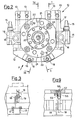
- FIGS 1 and 4 show the main part 10, which is fixed by screws to the end 11 of the manipulator arm (shown here by dashed and dotted lines).
- Said part 10 is formed from a plate 12, the upper zone of which comprises bores 13 which serve for receiving the pipes for the cooling water and oil which operates the electrode closing cylinder of the welding gun.
- Said bores 13 are formed such that their outlets lie in a predetermined position, from which they continue as described hereinafter.
- Two copper blocks 14 (Figure 2) each comprising contact cones (a bored male cone 15 for cooling purposes and a female cone 16 for the passage of electric current) are fixed laterally to said bored part, one on each side, by way of insulation.
- Two brackets 18 are fixed by screws 17 to the lower part of the plate 12, and each carries a proximity sensor 19 which, by being acted upon or not according to the case in point, identifies the type of gun carried (this device is better illustrated in Figure 3).
- the central part of the plate 12 comprises a bore 20 which serves for centering an intermediate member 21.
- the intermediate member 21 fixed to the plate 12 carries two very tapering cones 22 which from their base extend in the form of a cylinder 23 ( Figure 1), they being used for centering purposes when the two separable main parts, namely that heretofore described fixed to the arm and that described hereinafter fixed to the gun, are in a facing position.
- the periphery of the intermediate member 21 comprises bores 24 perpendicular to the support surface, these corresponding in position with the bores 13 when the plate 12 is in a predetermined position, and being designed to contain the sleeves 25 (Figure 1) of the valve units for the passage of the service liquids.
- Said valve units are constituted by a plunger 26 which slides in the sleeve 25, and is provided with peripheral bores 27 for the passage of the liquids and with a seal gasket 28 which, when the main parts are separated, engages with and is kept held by means of a spring 30 against a conical surface 29 provided in the end of the sleeve 25.
- Said plunger terminates in a stem 31 projecting from the sleeve 25, its purpose being to open the units (as illustrated in Figure 1), as described hereinafter.
- the centre of the intermediate member 21 comprises a large sized bore 32 which acts as a cylindrical housing for containing a slidable piston 33.
- a further bore 34 ( Figures 4a and 4b) perpendicular to the preceding reaches with its lower end the interior of the bore 21, its purpose being to act as a passage for the oil for moving the said piston 33.
- the interior of the piston houses a sleeve 35, the end 36 of which rests against the piston 33, and the cylindrical body of which extends outwards with an annular gap 37, to enlarge as soon as it is outside its container into a larger diameter 38 with a front spherical surface which rests on a cone 39 provided in the plate 40 which closes the entire assembly by means of screws 41 which engage in the intermediate member 21.
- the said sleeve 35 terminates externally to the plate 40 in a hardened edge 42 of particular shape, arranged to retain a body which strikes it and comprising longitudinal slots which make it resilient about its axis.
- Inside said sleeve 35 there is stacked a plurality of cup springs 43 kept in a preloaded position by means of a nut 44 engaged with a coaxial screw 45 which passes within the springs 43, and is sealed against annular gaskets 46 both against the piston 33 and against the intermediate member 21.
- the other separable main part 50 which is fixed to the electric welding gun (not shown) is shown in Figures 5 to 9, and consists of a plate 51, the centre of which comprises a bore 52 for centering the gun, and the periphery of which comprises bores for fixing it by screws to the upper member described hereinafter.
- the ends of the plate comprise lugs 53 provided with slots 54 which serve for guiding and centering the entire assembly when at rest on its support fitting to the side of the welding line.
- the upper member 59 resting on said plate 51 is provided with bores 61 fitted with bushes 60 (see Figure 9) which serve for receiving the cones 22 terminating in the cylinder 23 (described with reference to Figure 1) and positioned on the other separable part 10, and which serve for centering when the two parts 10 and 50 face each other.
- Bores 62 are provided in a predetermined position in said member 59, and are designed to receive their own valve groups identical to those described with reference to Figure 1 which exist on the other separable part 10, and which are in a facing position when the two parts are mutually inserted.
- valve units The constituent elements of the valve units will not be described as they are identical to those illustrated previously with the reference numerals 25-31.
- Two copper blocks 63 shown in Figure 6 and more clearly in Figures 7 and 8 are fixed laterally to the upper member 59, one on each side, and insulated therefrom, these comprising two opposing conical ends 64 and 66 which are cooled by ducts 65 and allow passage of the welding current.
- the two conical ends 66 facing outwards mate with the respective conical bores 16 of Figure 2 in the other separable part 10.
- the copper blocks 63 are fixed resiliently to the upper member in order to ensure correct coupling of the electrical contacts in all cases, as can be seen in Figure 8.
- Said resilient fixing is done by two screws 67 (one on each side of each block), which can slide along their own axis and into the respective containing compartment to coaxially engage the stacks of cup springs 68 which, when urged by the coupling of the cones 66, thrust these latter forcibly into the bores 16.
- the coupling member is enclosed in the central zone between the plate 51 and upper member 59, and is fixed by screws 69 to this latter, the said coupling member comprising a collar 70 ( Figure 5) of hard material which is coupled to and retained annularly in a stable manner on the sleeve 35 ( Figure 1) of the separable main part on the manipulator by means of the hook portion 71.
- the assembly can be provided with further oil passage bores fitted with identical valve units (as heretofore described) to allow partial closure of the gun, this operation being required (to save time) when more than one weld has to be made in a uniform zone.
- the operation of the device heretofore described takes place as described hereinafter, account being taken of the fact that the electric welding guns can be more than two in number and being arranged on their own container support disposed to the sides of the line.
- the programmable manipulator receives the starting signal from its control section, and the welding gun can either be coupled or not to the end of its arm, but for ease of description it will be assumed that the arm is not yet fitted with it.
- the end 11 ( Figure 1) is already provided with its own separable main part 12 (common to all types of gun) which is already suitably connected to the service pipes by way of the ducts 13, 24, and to the welding current cables by way of the cones 15 and 16 of the blocks 14, whether dealing with the type in which the welding transformer is incorporated or the type in which the transformer is overhead, the closed valve units (as in Figure 1) being connected to said pipes 13 and 24.
- said manipulator then moves the entire assembly towards the container support which supports the selected gun, which is already complete with its own separable main part 50 with its coupling and mating means facing upwards, and connected to said gun by way of its own hollow ducts 62 and valve units.
- the main parts lie facing each other but still spaced apart, and the descent operation then begins in which the cones 22, which are followed by cylinders 23 and are positioned on the intermediate member 21 of the main part 10 on the manipulator, engage the corresponding bores 61 comprising the bush 60 on the upper member 59 of the main part 50 fixed to the gun.
- the manipulator arm causes the two main parts 10 and 50 to increasingly approach each other, so that the valve units of the main part on the manipulator become inserted into the respective bores to form an annular seal (which prevents leakage of liquids when the valve units are opened).
- the conical heads 31 of the two valve units project slightly from the surfaces of the sleeve 25 and member 59, the former of which is inserted into the latter, so that when they meet head-on, they urge in opposite directions the plungers 26 with which each head 31 is rigid.
- the activation signal arrives from the manipulator control system for the passage of pressurised oil through the pipe connected to the bore 34 of Figures 4a and 4b which leads to the cylinder 32 located in the centre of the intermediate member 21 of the separable main part 10 on the manipulator side.
- Said oil pushes the piston 33 contained in the cylinder 32 outwards to consequently drive the sleeve 35 contained therein, which overcomes the reaction of the cup springs 43 located in its interior so that its spherical annular surface 38 engages the respective conical portion 39 provided in the upper closing plate 40, thus, by virtue of the longitudinal slots which characterise it, causing a restriction of the annular edged sectors 42 of its end.
- the manipulator In order to change this gun, the manipulator carries out the reverse movements to those described, and deposits this gun on its support, passes to a new gun, recouples the new gun and begins a new welding cycle.
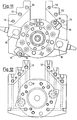
- Figures 10 to 13 show a second embodiment of the device according to the invention.
- At least one intermediate position of the gun can be programmed (the more ducts provided the more of the number of intermediate positions which can be attained).
Landscapes
- Engineering & Computer Science (AREA)
- Mechanical Engineering (AREA)
- Robotics (AREA)
- Resistance Welding (AREA)
Description
- The invention relates to an automatic device for changing an electric welding gun operated by the arm of a programmable manipulator.
- It becomes necessary to change a welding gun when, during determined welding cycles, it becomes impossible to penetrate into each recess in the piece to be welded with a single type of gun, and it is therefore not possible to make proper welds without replacing the gun with others of different shapes and dimensions.
- Another case in which change-over is necessary occurs when it is undesirable to incorporate into the cycle other welding machines carrying a gun more suitable for the specific operation, or again when it is required to carry out other welding operations on a different line during the down-times of the main cycle.
- It is obvious that to operate under such conditions, even with automatic means, is extremely costly and of poor efficiency.
- The patent FR-A-2.426.548 shows an automatic device for changing an electric welding gun, operated by the arm of a programmable manipulator and disposed between the end of the arm of the programmable manipulator and the electric welding gun, comprising: two elements, which are rigid with the manipulator arm and the welding gun respectively, and which can be connected together in a separable manner; the device further provides lead-in guide means forming part of the two elements for their mutual insertion and means for releasably coupling together the two elements at the end of their mutual insertion movement.
- The above device, however, does not provide means for checking the correct selection of the closen type of gun and for checking that the element carried by the arm has properly approached this latter.
- Furthermore the two elements are not provided with ducts for passage of the liquid for cooling, controlled by valve units which connect said ducts to each other when the two elements are fitted together.
- The patent US-A-3.229.656 describes a device providing means for quickly connecting and disconnecting manipulator arms from subsea vehicles. The device provides means for connecting and disconnecting both mechanical and circumferentially located hydraulic connections between the vehicle and manipulator arms at the same time.
- According to the -device however the mechanical connection is realized by means of one centrally located jack-screw rotated by personnel from within the vehicle, and the hydraulic supply is realized by means of manual actuated valves.
- The main object of the invention is to completely automate the change-over of an electric welding gun operated by a programmable manipulator.
- For these reasons, the invention proposes to provide an automatic changing device for welding guns which, by means of two simple and rapid movements of the manipulator, with the first of which releases the gun which has already executed part of the cycle, and breaks the connections (water for cooling the electric contacts and electrodes, oil for the electrode closing cylinder), and with the second of which couples the new gun and simultaneously remakes the said connections without creating losses of pressurised service liquids, so that the cycle which was interrupted a moment previously can be continued.
- This and further objects which will be more apparent hereinafter are attained according to the present invention by an automatic device for changing an electric welding gun operated by the arm of a programmable manipulator and disposed between the end of the arm of the programmable manipulator and the electric welding gun, comprising: two elements which are rigid with the manipulator arm and the welding gun respectively, and which can be connected together in a separable manner, lead-in guide means forming part of the two elements for their mutual insertion and means for releasably coupling together the two elements at the end of their mutual insertion movement, characterised in that the device comprises means for checking the correct selection of the chosen type of gun and for checking that the element carried by the arm has properly approached the element carried by the gun, valve units which automatically open during the coupling together of the two elements in order to directly connect together the ducts in the two elements for the passage of firstly liquid for cooling the electrical contacts and electrodes of the gun and secondly oil for an electrode closing cylinder of the gun, the electrical connection between the manipulator and gun being made by means of two male and two female contacts, the one of each pair provided on the element rigid with the arm and the other of each pair in the element rigid with the gun and being coupled together at the moment in which said elements become connected together.
- Two embodiments of the device according to the invention are described hereinafter by way of non-limiting example with reference to the drawings in which:
- Figure 1 is a section on the line I-I of Figure 2, which is a front view of a detail of the device according to the invention;
- Figure 3 is a view of a detail of Figure 2 along the arrow A;
- Figure 4a and 4b are views of a detail of Figure 1 in two different working positions;
- Figure 5 is a section on the line V-V of Figure 6, which is a front view of a further detail of the device according to the invention;
- Figure 7, 8 and 9 are views of the detail of Figures 6 and 7 along the arrows B, C and D respectively;
- Figure 10 is an axial section of a second embodiment of the device according to the invention taken through the two details of Figures 1 and 5 when coupled together;
- Figures 11, 12 and 13 are sections on the lines XI-XI, XII-XII and XIII-XIII respectively, of the device of Figure 10.
- Figures 1 and 4 show the
main part 10, which is fixed by screws to theend 11 of the manipulator arm (shown here by dashed and dotted lines). Saidpart 10 is formed from aplate 12, the upper zone of which comprisesbores 13 which serve for receiving the pipes for the cooling water and oil which operates the electrode closing cylinder of the welding gun. Saidbores 13 are formed such that their outlets lie in a predetermined position, from which they continue as described hereinafter. - Two copper blocks 14 (Figure 2) each comprising contact cones (a bored
male cone 15 for cooling purposes and afemale cone 16 for the passage of electric current) are fixed laterally to said bored part, one on each side, by way of insulation. Twobrackets 18 are fixed byscrews 17 to the lower part of theplate 12, and each carries aproximity sensor 19 which, by being acted upon or not according to the case in point, identifies the type of gun carried (this device is better illustrated in Figure 3). - Finally, the central part of the
plate 12 comprises abore 20 which serves for centering anintermediate member 21. - The
intermediate member 21 fixed to theplate 12 carries two verytapering cones 22 which from their base extend in the form of a cylinder 23 (Figure 1), they being used for centering purposes when the two separable main parts, namely that heretofore described fixed to the arm and that described hereinafter fixed to the gun, are in a facing position. The periphery of theintermediate member 21 comprisesbores 24 perpendicular to the support surface, these corresponding in position with thebores 13 when theplate 12 is in a predetermined position, and being designed to contain the sleeves 25 (Figure 1) of the valve units for the passage of the service liquids. Said valve units are constituted by aplunger 26 which slides in thesleeve 25, and is provided withperipheral bores 27 for the passage of the liquids and with aseal gasket 28 which, when the main parts are separated, engages with and is kept held by means of aspring 30 against aconical surface 29 provided in the end of thesleeve 25. Said plunger terminates in astem 31 projecting from thesleeve 25, its purpose being to open the units (as illustrated in Figure 1), as described hereinafter. - The centre of the
intermediate member 21 comprises a large sizedbore 32 which acts as a cylindrical housing for containing aslidable piston 33. A further bore 34 (Figures 4a and 4b) perpendicular to the preceding reaches with its lower end the interior of thebore 21, its purpose being to act as a passage for the oil for moving the saidpiston 33. - As can be seen in Figure 1 and better in Figures 4a and 4b, the interior of the piston houses a
sleeve 35, theend 36 of which rests against thepiston 33, and the cylindrical body of which extends outwards with anannular gap 37, to enlarge as soon as it is outside its container into alarger diameter 38 with a front spherical surface which rests on acone 39 provided in theplate 40 which closes the entire assembly by means of screws 41 which engage in theintermediate member 21. - The said
sleeve 35 terminates externally to theplate 40 in a hardenededge 42 of particular shape, arranged to retain a body which strikes it and comprising longitudinal slots which make it resilient about its axis. Inside saidsleeve 35 there is stacked a plurality ofcup springs 43 kept in a preloaded position by means of anut 44 engaged with acoaxial screw 45 which passes within thesprings 43, and is sealed againstannular gaskets 46 both against thepiston 33 and against theintermediate member 21. - The other separable
main part 50 which is fixed to the electric welding gun (not shown) is shown in Figures 5 to 9, and consists of aplate 51, the centre of which comprises abore 52 for centering the gun, and the periphery of which comprises bores for fixing it by screws to the upper member described hereinafter. The ends of the plate compriselugs 53 provided withslots 54 which serve for guiding and centering the entire assembly when at rest on its support fitting to the side of the welding line. Into each of two of the lugs 53 (the lower outer part of Figure 6) there is fixed ascrew 55 supported by aspring 56 and held in the predetermined position by a nut 57 (see Figure 9 in detail), thescrew 55 comprising at the end of its threaded portion aslot 58 for adjusting the gap which arises relative to thesensor 19 disposed on the other separable part, and of which the purpose, as already described with reference to Figure 3, is to recognise the type of gun which is coupled. In this respect, saidsensor 19 is shown diagrammatically in Figure 9 in its working position. Theupper member 59 resting on saidplate 51 is provided withbores 61 fitted with bushes 60 (see Figure 9) which serve for receiving thecones 22 terminating in the cylinder 23 (described with reference to Figure 1) and positioned on the otherseparable part 10, and which serve for centering when the twoparts member 59, and are designed to receive their own valve groups identical to those described with reference to Figure 1 which exist on the otherseparable part 10, and which are in a facing position when the two parts are mutually inserted. - The constituent elements of the valve units will not be described as they are identical to those illustrated previously with the reference numerals 25-31.
- Two
copper blocks 63 shown in Figure 6 and more clearly in Figures 7 and 8 are fixed laterally to theupper member 59, one on each side, and insulated therefrom, these comprising two opposingconical ends ducts 65 and allow passage of the welding current. The twoconical ends 66 facing outwards mate with the respectiveconical bores 16 of Figure 2 in the otherseparable part 10. In addition, besides being insulated from the rest of the apparatus, thecopper blocks 63 are fixed resiliently to the upper member in order to ensure correct coupling of the electrical contacts in all cases, as can be seen in Figure 8. Said resilient fixing is done by two screws 67 (one on each side of each block), which can slide along their own axis and into the respective containing compartment to coaxially engage the stacks ofcup springs 68 which, when urged by the coupling of thecones 66, thrust these latter forcibly into thebores 16. The coupling member is enclosed in the central zone between theplate 51 andupper member 59, and is fixed byscrews 69 to this latter, the said coupling member comprising a collar 70 (Figure 5) of hard material which is coupled to and retained annularly in a stable manner on the sleeve 35 (Figure 1) of the separable main part on the manipulator by means of thehook portion 71. - In addition to these components, the assembly can be provided with further oil passage bores fitted with identical valve units (as heretofore described) to allow partial closure of the gun, this operation being required (to save time) when more than one weld has to be made in a uniform zone.
- The operation of the device heretofore described takes place as described hereinafter, account being taken of the fact that the electric welding guns can be more than two in number and being arranged on their own container support disposed to the sides of the line. At the beginning of the cycle, the programmable manipulator receives the starting signal from its control section, and the welding gun can either be coupled or not to the end of its arm, but for ease of description it will be assumed that the arm is not yet fitted with it.
- The end 11 (Figure 1) is already provided with its own separable main part 12 (common to all types of gun) which is already suitably connected to the service pipes by way of the
ducts cones blocks 14, whether dealing with the type in which the welding transformer is incorporated or the type in which the transformer is overhead, the closed valve units (as in Figure 1) being connected to saidpipes main part 50 with its coupling and mating means facing upwards, and connected to said gun by way of its ownhollow ducts 62 and valve units. - After this stage, the main parts lie facing each other but still spaced apart, and the descent operation then begins in which the
cones 22, which are followed bycylinders 23 and are positioned on theintermediate member 21 of themain part 10 on the manipulator, engage thecorresponding bores 61 comprising thebush 60 on theupper member 59 of themain part 50 fixed to the gun. As it continues its descent, the manipulator arm causes the twomain parts ducts - The
conical heads 31 of the two valve units project slightly from the surfaces of thesleeve 25 andmember 59, the former of which is inserted into the latter, so that when they meet head-on, they urge in opposite directions theplungers 26 with which eachhead 31 is rigid. The condition shown in Figures 1 and 5 thus arises, in which thesprings 30 are compressed and theplungers 26 have moved towards the end of eachsleeve 26 in which they slide, so that the liquid contained in theduct plunger 26 between thespring 30 and bores 27 to flow through the now open duct between theconical wall 29 of thesleeve 25 and theconical head 31, because thegasket 28 no longer rests against the outlet of thesleeve 25 provided at the point in which the sleeve abuts against the corresponding part of theelement 59. The same happens in the case of the valve unit carried by theplate 59, so that the liquid originating from theopen duct ducts 62 to establish the required continuity between the manipulator and gun. Themale cones 66 andfemale cones 16 of theelectrical contacts cup springs 68 contained in the side compartments of theelectrical assemblies 63 and guided by thescrews 67 which keep thecopper blocks 63 suspended. - At the same tine, the activation signal arrives from the manipulator control system for the passage of pressurised oil through the pipe connected to the
bore 34 of Figures 4a and 4b which leads to thecylinder 32 located in the centre of theintermediate member 21 of the separablemain part 10 on the manipulator side. Said oil pushes thepiston 33 contained in thecylinder 32 outwards to consequently drive thesleeve 35 contained therein, which overcomes the reaction of thecup springs 43 located in its interior so that its sphericalannular surface 38 engages the respectiveconical portion 39 provided in theupper closing plate 40, thus, by virtue of the longitudinal slots which characterise it, causing a restriction of the annularedged sectors 42 of its end. - It thus passes from the rest position of Figure 4a to that shown in Figure 4b. At this point, with the final approach of the two
main parts annular sectors 42 penetrate into thecoupling member 71 contained between theplate 51 andupper member 59 of the separable main part of the gun, and the hydraulic pressure operating thepiston 33 ceases only at this moment so that thecup springs 43 which oppose thesleeve 35 urge thepiston 33 towards its rest position, to consequently induce theconical surface 38 engaged in thespherical surface 39 to abandon this as shown in Figure 1 and 5, so causing theannular sectors 42 to expand (because of their resilience), and hook on to thecoupling member 71, so providing the stable coupling between the two main parts. At the same time, thesensor 19 of Figures 3 and 9 becomes located in front of itsopposing element 55, and provides a signal to the manipulator control system which analyses whether the gun is the correct one, and then initiates normal working. - In order to change this gun, the manipulator carries out the reverse movements to those described, and deposits this gun on its support, passes to a new gun, recouples the new gun and begins a new welding cycle.
- Figures 10 to 13 show a second embodiment of the device according to the invention.
- The difference between this and the embodiment heretofore described is that the
feed ducts 13 for the cooling water and oil operating the electrode closure cylinder of the welding gun are now present in a number greater than those of the preceding embodiment, theducts 62 of the fixed part of the gun being present in a number equal to theducts 13. - The reference numerals on the
drawings 10 to 13 for the parts corresponding to those previously illustrated remain unchanged for obvious reasons of simplicity of description. - The advantage offered by this second embodiment is only that of being able to attain one or more intermediate closure positions for the gun.
- In this respect, for certain operations it can be useful to keep the gun semi-closed during non-working passage from one weld to the next, and so on for a long series of welds of the same type.
- Thus, if the gun is not completely open each time one weld is terminated, considerable down-time, i.e. non-working time is saved, and the sum of the times saved is such that the entire welding cycle can take place in a much shorter overall time.
- Thus by providing more than one set of feed and return
ducts
Claims (8)
Applications Claiming Priority (2)
| Application Number | Priority Date | Filing Date | Title |
|---|---|---|---|
| IT6799480 | 1980-06-26 | ||
| IT67994/80A IT1129104B (en) | 1980-06-26 | 1980-06-26 | AUTOMATIC DEVICE FOR CHANGE OF ELECTRIC WELDING CALIPER OPERATED BY THE ARM OF A PROGRAMMABLE MANIPULATOR |
Publications (3)
| Publication Number | Publication Date |
|---|---|
| EP0043153A2 EP0043153A2 (en) | 1982-01-06 |
| EP0043153A3 EP0043153A3 (en) | 1982-01-13 |
| EP0043153B1 true EP0043153B1 (en) | 1984-03-28 |
Family
ID=11307037
Family Applications (1)
| Application Number | Title | Priority Date | Filing Date |
|---|---|---|---|
| EP81200649A Expired EP0043153B1 (en) | 1980-06-26 | 1981-06-12 | Automatic device for changing an electric welding gun, operated by the arm of a programmable manipulator |
Country Status (7)
| Country | Link |
|---|---|
| US (1) | US4409464A (en) |
| EP (1) | EP0043153B1 (en) |
| JP (1) | JPS5739082A (en) |
| DE (1) | DE3162869D1 (en) |
| ES (1) | ES503891A0 (en) |
| IT (1) | IT1129104B (en) |
| SU (1) | SU1058492A3 (en) |
Families Citing this family (32)
| Publication number | Priority date | Publication date | Assignee | Title |
|---|---|---|---|---|
| US4492847A (en) * | 1981-09-30 | 1985-01-08 | Unimation, Inc. | Manipulator welding apparatus with sensing arrangements for weld slam tracking |
| JPS58156671A (en) * | 1982-03-12 | 1983-09-17 | 日産自動車株式会社 | Remote opening and closing apparatus of door for automobile |
| US4621398A (en) * | 1982-12-06 | 1986-11-11 | Rockwell International Corporation | Automaton tool mounting system |
| JPS59125282A (en) * | 1982-12-28 | 1984-07-19 | Nissan Motor Co Ltd | Mounting device for spot welding gun in welding robot |
| IT1167223B (en) * | 1983-09-29 | 1987-05-13 | Rosa Gaetano Di | AUTOMATIC SYSTEM FOR ASSEMBLING AND WELDING OF AUTOMATIC BODIES, SUITABLE FOR VERY HIGH PRODUCTIONS |
| EP0150232A1 (en) * | 1984-01-26 | 1985-08-07 | Wilhelm Karmann GmbH | Process for running an industrial robot, and industrial robot used in this process |
| IT1179967B (en) * | 1984-02-13 | 1987-09-23 | Bisiach & Carru | MECHANISM FOR THE AUTOMATIC CHANGE OF TOOLS ON INDUSTRIAL ROBOTS |
| DE3421452C2 (en) * | 1984-06-08 | 1986-05-22 | Kuka Schweissanlagen + Roboter Gmbh, 8900 Augsburg | Device for the automatic gripping or releasing of a tool carrier in a manipulator |
| GB8426225D0 (en) * | 1984-10-17 | 1984-11-21 | Plessey Co Plc | Robot machines |
| FR2578775B1 (en) * | 1985-03-13 | 1988-10-14 | Dassault Avions | DEVICE FOR COUPLING A TOOL HEAD TO THE MANIPULATOR ARM OF A ROBOT, AND SUPPORT FOR STORING SUCH HEAD TOOLS |
| DE3509632A1 (en) * | 1985-03-16 | 1986-09-18 | Bayerische Motoren Werke AG, 8000 München | Welding robot |
| FR2587930B1 (en) * | 1985-05-30 | 1989-11-10 | Steelweld France | DEVICE FOR RECEIVING AND STORING TOOLS IN ASSEMBLY LINES |
| GB2179306B (en) * | 1985-07-22 | 1989-08-09 | Honda Motor Co Ltd | A welding apparatus |
| IT1193450B (en) * | 1986-07-16 | 1988-06-22 | Comau Spa | DEVICE FOR THE AUTOMATIC CHANGE OF INDUSTRIAL ROBOT TOOLS |
| FR2612109B3 (en) * | 1987-03-11 | 1989-10-06 | Renault Automation Sa | ROBOT TOOL CHANGING DEVICE |
| US4809747A (en) * | 1987-07-31 | 1989-03-07 | General Motors Corporation | Quick disconnect device |
| FR2619740B1 (en) * | 1987-08-25 | 1992-10-16 | Aerospatiale | ADAPTABLE GRIPPING DEVICE ON A ROBOT |
| JPH046376U (en) * | 1990-05-07 | 1992-01-21 | ||
| US5073692A (en) * | 1990-11-13 | 1991-12-17 | Jackson Donald T | Automatic welding electrode cap changer |
| JP2568365Y2 (en) * | 1992-01-17 | 1998-04-08 | 小原株式会社 | Robot gun device with gun changer |
| DE4207114C2 (en) * | 1992-03-06 | 2003-10-02 | Binzel Alexander Gmbh Co Kg | Tool changing device |
| US5591358A (en) * | 1994-03-23 | 1997-01-07 | Progressive Tool & Industries Co. | Apparatus for clamping and laser welding |
| GB2289668A (en) * | 1994-05-23 | 1995-11-29 | Oxford Intelligent Machines Lt | Interchangeable Tool Holders |
| US6116966A (en) * | 1998-04-17 | 2000-09-12 | Ati Industrial Automation, Inc. | High power electrical contacts for robotic tool changer |
| US6491612B1 (en) | 2000-10-23 | 2002-12-10 | Ati Industrial Automation, Inc. | Stud welding tool changer |
| US9050671B2 (en) * | 2011-09-28 | 2015-06-09 | Turbine Engine Components Technologies Corporation | Electrode holder for EDM coupled to a milling machine |
| ITBS20120145A1 (en) * | 2012-10-11 | 2014-04-12 | Gimatic Spa | PNEUMATIC TOOL CONNECTION DEVICE TO A MANIPULATOR |
| ITUB20160939A1 (en) * | 2016-02-23 | 2017-08-23 | Gimatic S R L | Device for connecting pneumatic tools to a manipulator |
| US10814420B2 (en) | 2018-09-25 | 2020-10-27 | Deere & Company | Automatic tip changer for burnback in an arc welding robot |
| CN111219551B (en) * | 2020-03-09 | 2025-01-07 | 淮安市博泽科技有限公司 | Robotic quick changer for water cooling system |
| CN116551272B (en) * | 2023-06-01 | 2023-10-13 | 发哲(浙江)新材料科技有限公司 | Steel pipe welding machine with adjusting function |
| CN119952329A (en) * | 2025-03-19 | 2025-05-09 | 中国航发北京航空材料研究院 | A wax mold assembly welding device with wax mold cleaning function and a wax mold assembly method |
Family Cites Families (10)
| Publication number | Priority date | Publication date | Assignee | Title |
|---|---|---|---|---|
| US3148264A (en) * | 1961-08-11 | 1964-09-08 | Sippican Corp | Preset, interchangeable welding heads |
| US3229656A (en) * | 1964-06-25 | 1966-01-18 | North American Aviation Inc | Manipulator arm attachment |
| US3673541A (en) * | 1970-08-06 | 1972-06-27 | Amp Inc | Composite electrical and fluid or air connector |
| GB1461299A (en) * | 1974-06-24 | 1977-01-13 | Siv Deltix Spa | Electric resistance welding machine with removable welding gun |
| GB1587787A (en) * | 1977-04-18 | 1981-04-08 | Inoue Japax Res | Electroerosion machining apparatus and methods |
| US4142086A (en) * | 1977-05-12 | 1979-02-27 | Rotilio James V | Combination welding torch for shielded inert gas or electric arc welding |
| FR2426548A1 (en) * | 1978-05-24 | 1979-12-21 | Renault | Tool coupling for automatic production machine - has two tool changers with eccentric elements and tool store |
| SU664784A1 (en) * | 1978-03-03 | 1979-05-30 | Предприятие П/Я Г-4086 | Resistance spot welding head |
| CH627109A5 (en) * | 1979-03-09 | 1981-12-31 | Charmilles Sa Ateliers | |
| US4270824A (en) * | 1979-03-30 | 1981-06-02 | Dover Corporation | Electrical clamp |
-
1980
- 1980-06-26 IT IT67994/80A patent/IT1129104B/en active
-
1981
- 1981-06-12 DE DE8181200649T patent/DE3162869D1/en not_active Expired
- 1981-06-12 EP EP81200649A patent/EP0043153B1/en not_active Expired
- 1981-06-16 US US06/274,237 patent/US4409464A/en not_active Expired - Fee Related
- 1981-06-25 SU SU813302796A patent/SU1058492A3/en active
- 1981-06-26 JP JP9953881A patent/JPS5739082A/en active Pending
- 1981-06-26 ES ES503891A patent/ES503891A0/en active Granted
Also Published As
| Publication number | Publication date |
|---|---|
| US4409464A (en) | 1983-10-11 |
| EP0043153A2 (en) | 1982-01-06 |
| IT8067994A0 (en) | 1980-06-26 |
| DE3162869D1 (en) | 1984-05-03 |
| JPS5739082A (en) | 1982-03-04 |
| ES8203254A1 (en) | 1982-04-16 |
| SU1058492A3 (en) | 1983-11-30 |
| EP0043153A3 (en) | 1982-01-13 |
| ES503891A0 (en) | 1982-04-16 |
| IT1129104B (en) | 1986-06-04 |
Similar Documents
| Publication | Publication Date | Title |
|---|---|---|
| US4409464A (en) | Automatic device for changing an electric welding gun, operated by the arm of a programmable manipulator | |
| US4763401A (en) | Automatic tool-changing device for industrial robots | |
| US3677682A (en) | Hot runner system | |
| US4600824A (en) | Arc welding system and docking assembly therefor | |
| US4582979A (en) | Arc welding system and docking assembly therefor | |
| US7850442B2 (en) | Edge-gated nozzle | |
| KR20060033907A (en) | Apparatus and method for dispensing discrete amounts of viscous material | |
| US20210394262A1 (en) | Connection device and connection assembly | |
| JPS63109032A (en) | Valve gate type injection molding equipment | |
| US4557292A (en) | System for distributing pneumatic control signals by electrical means | |
| WO2018056061A1 (en) | Tool exchange device | |
| US20030042340A1 (en) | Voltage block and color change apparatus for waterborne bell applicator | |
| US6553663B2 (en) | Method of installing a protective connector assembly in a hermetic compressor | |
| US4515677A (en) | Apparatus for electrocoating | |
| US5818007A (en) | Gun arm exchange structure for spot welding gun and method for the same | |
| US3054074A (en) | Termination device with removable center conductor | |
| JP3255955B2 (en) | Vacuum induction melting assembly with simultaneous actuation cooling and power connection | |
| US2630347A (en) | Fluid dispensing apparatus | |
| US6422491B1 (en) | Method and device for isolating an electro-conductive flowing medium | |
| CN219734226U (en) | Down-pressure discharge valve | |
| KR890004508B1 (en) | Apparatus for connecting cooling water to water-cooled composite electrodes of electric arc | |
| AU634850B2 (en) | Pilot controlled liquid actuated coolant control valves | |
| SU1198221A1 (en) | Valve unit of power support | |
| SU543513A1 (en) | Docking device | |
| US3066216A (en) | Resistance welding gun |
Legal Events
| Date | Code | Title | Description |
|---|---|---|---|
| PUAI | Public reference made under article 153(3) epc to a published international application that has entered the european phase |
Free format text: ORIGINAL CODE: 0009012 |
|
| PUAL | Search report despatched |
Free format text: ORIGINAL CODE: 0009013 |
|
| AK | Designated contracting states |
Designated state(s): DE FR GB SE |
|
| AK | Designated contracting states |
Designated state(s): DE FR GB SE |
|
| 17P | Request for examination filed |
Effective date: 19820322 |
|
| GRAA | (expected) grant |
Free format text: ORIGINAL CODE: 0009210 |
|
| AK | Designated contracting states |
Designated state(s): DE FR GB SE |
|
| REF | Corresponds to: |
Ref document number: 3162869 Country of ref document: DE Date of ref document: 19840503 |
|
| ET | Fr: translation filed | ||
| PGFP | Annual fee paid to national office [announced via postgrant information from national office to epo] |
Ref country code: FR Payment date: 19840620 Year of fee payment: 4 |
|
| PGFP | Annual fee paid to national office [announced via postgrant information from national office to epo] |
Ref country code: SE Payment date: 19840630 Year of fee payment: 4 |
|
| PGFP | Annual fee paid to national office [announced via postgrant information from national office to epo] |
Ref country code: DE Payment date: 19840822 Year of fee payment: 4 |
|
| PLBE | No opposition filed within time limit |
Free format text: ORIGINAL CODE: 0009261 |
|
| STAA | Information on the status of an ep patent application or granted ep patent |
Free format text: STATUS: NO OPPOSITION FILED WITHIN TIME LIMIT |
|
| 26N | No opposition filed | ||
| PG25 | Lapsed in a contracting state [announced via postgrant information from national office to epo] |
Ref country code: SE Effective date: 19860613 |
|
| PG25 | Lapsed in a contracting state [announced via postgrant information from national office to epo] |
Ref country code: FR Free format text: LAPSE BECAUSE OF NON-PAYMENT OF DUE FEES Effective date: 19870227 |
|
| PG25 | Lapsed in a contracting state [announced via postgrant information from national office to epo] |
Ref country code: DE Effective date: 19870303 |
|
| GBPC | Gb: european patent ceased through non-payment of renewal fee | ||
| REG | Reference to a national code |
Ref country code: FR Ref legal event code: ST |
|
| PG25 | Lapsed in a contracting state [announced via postgrant information from national office to epo] |
Ref country code: GB Effective date: 19881118 |
|
| EUG | Se: european patent has lapsed |
Ref document number: 81200649.2 Effective date: 19870504 |