EP0043082B1 - Kollektor für Sonnenlichtenergie - Google Patents
Kollektor für Sonnenlichtenergie Download PDFInfo
- Publication number
- EP0043082B1 EP0043082B1 EP81104841A EP81104841A EP0043082B1 EP 0043082 B1 EP0043082 B1 EP 0043082B1 EP 81104841 A EP81104841 A EP 81104841A EP 81104841 A EP81104841 A EP 81104841A EP 0043082 B1 EP0043082 B1 EP 0043082B1
- Authority
- EP
- European Patent Office
- Prior art keywords
- lens
- lens system
- sun
- fresnel
- optical energy
- Prior art date
- Legal status (The legal status is an assumption and is not a legal conclusion. Google has not performed a legal analysis and makes no representation as to the accuracy of the status listed.)
- Expired
Links
- 230000003287 optical effect Effects 0.000 title claims description 17
- 239000002775 capsule Substances 0.000 claims description 21
- 239000004020 conductor Substances 0.000 claims description 5
- 239000000463 material Substances 0.000 claims description 2
- 238000011161 development Methods 0.000 description 2
- 230000018109 developmental process Effects 0.000 description 2
- 238000011160 research Methods 0.000 description 2
- 239000000126 substance Substances 0.000 description 2
- 238000013459 approach Methods 0.000 description 1
- 239000012141 concentrate Substances 0.000 description 1
- 238000010276 construction Methods 0.000 description 1
- 230000007547 defect Effects 0.000 description 1
- 238000013461 design Methods 0.000 description 1
- 239000000428 dust Substances 0.000 description 1
- 239000011521 glass Substances 0.000 description 1
- 238000004519 manufacturing process Methods 0.000 description 1
- 238000000034 method Methods 0.000 description 1
- 239000012780 transparent material Substances 0.000 description 1
Images


Classifications
-
- F—MECHANICAL ENGINEERING; LIGHTING; HEATING; WEAPONS; BLASTING
- F24—HEATING; RANGES; VENTILATING
- F24S—SOLAR HEAT COLLECTORS; SOLAR HEAT SYSTEMS
- F24S23/00—Arrangements for concentrating solar-rays for solar heat collectors
- F24S23/30—Arrangements for concentrating solar-rays for solar heat collectors with lenses
- F24S23/31—Arrangements for concentrating solar-rays for solar heat collectors with lenses having discontinuous faces, e.g. Fresnel lenses
-
- F—MECHANICAL ENGINEERING; LIGHTING; HEATING; WEAPONS; BLASTING
- F24—HEATING; RANGES; VENTILATING
- F24S—SOLAR HEAT COLLECTORS; SOLAR HEAT SYSTEMS
- F24S23/00—Arrangements for concentrating solar-rays for solar heat collectors
- F24S23/12—Light guides
-
- F—MECHANICAL ENGINEERING; LIGHTING; HEATING; WEAPONS; BLASTING
- F24—HEATING; RANGES; VENTILATING
- F24S—SOLAR HEAT COLLECTORS; SOLAR HEAT SYSTEMS
- F24S30/00—Arrangements for moving or orienting solar heat collector modules
- F24S30/40—Arrangements for moving or orienting solar heat collector modules for rotary movement
- F24S30/45—Arrangements for moving or orienting solar heat collector modules for rotary movement with two rotation axes
- F24S30/452—Vertical primary axis
-
- F—MECHANICAL ENGINEERING; LIGHTING; HEATING; WEAPONS; BLASTING
- F24—HEATING; RANGES; VENTILATING
- F24S—SOLAR HEAT COLLECTORS; SOLAR HEAT SYSTEMS
- F24S40/00—Safety or protection arrangements of solar heat collectors; Preventing malfunction of solar heat collectors
- F24S40/80—Accommodating differential expansion of solar collector elements
- F24S40/85—Arrangements for protecting solar collectors against adverse weather conditions
-
- Y—GENERAL TAGGING OF NEW TECHNOLOGICAL DEVELOPMENTS; GENERAL TAGGING OF CROSS-SECTIONAL TECHNOLOGIES SPANNING OVER SEVERAL SECTIONS OF THE IPC; TECHNICAL SUBJECTS COVERED BY FORMER USPC CROSS-REFERENCE ART COLLECTIONS [XRACs] AND DIGESTS
- Y02—TECHNOLOGIES OR APPLICATIONS FOR MITIGATION OR ADAPTATION AGAINST CLIMATE CHANGE
- Y02E—REDUCTION OF GREENHOUSE GAS [GHG] EMISSIONS, RELATED TO ENERGY GENERATION, TRANSMISSION OR DISTRIBUTION
- Y02E10/00—Energy generation through renewable energy sources
- Y02E10/40—Solar thermal energy, e.g. solar towers
- Y02E10/47—Mountings or tracking
Definitions
- the present invention relates to a solar optical energy collector, comprising a lens system for concentrating sun beams and a sun beam receiving system for introducing said sun beams into an optical-conductor cable.
- FR-A-2 359 381 discloses a field of frustroconical collecting tubes each cooperating with a solar cell
- FR-A-2 450 465 disclosing conventional and Fresnel type lenses subdivided into at least two elements which can be stacked to a compact unit when not in use
- DE-A-28 34 827 which in connection with a solar beam collector discloses a field of closely spaced hexagonal mirror elements.
- the present invention belongs to one of the above developments and research utilizing the radiative energy of the sun.
- the inventive solar energy collector overcomes the defects of the prior techniques. It solves the problems, firstly, by providing a novel arrangement of Fresnel lenses, each lens having the shape of a hexagon, arranged without gaps therebetween; secondly, by using a transparent spherical capsule which hermetically includes the Fresnel lenses; and thirdly, by turnably mounting the Fresnel lenses around two axes perpendicularly intersecting with each other at the centroid of the Fresnel lenses.
- the advantages offered by the present invention are that a plurality of Fresnel lenses can be disposed without gaps therebetween and can form substantially a big circular surface for sun beam concentrating as a whole, which results in providing the most effective arrangement of the Fresnel lenses.
- the influence from the wind can be prevented, and gyrating mass of the Fresnel lenses may be reduced to a minimum. Therefore, according to the present invention, the operation for tracking the movement of the sun can be performed very quickly and smoothly.
- Fig. 1 is a front elevation diagrammatically illustrating the structure of one embodiment of the solar optical energy collector according to the present invention
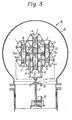
- Figs. 2 and 3 are side and rear elevation views, respectively of Fig. 1
- Fig. 4 is a rear elevation, similar to Fig. 3, of an alternate embodiment of the solar optical energy collector according to the present invention:
- the basic components of the solar optical energy collector include a Fresnel lens system for concentrating sun beams and a sun beam receiving system for introducing said sun beams being concentrated into an optical-conductor cable.
- the reference numeral 1 represents a Fresnel lens formed of a light transparent material, such as plastic or glass, used to concentrate sun beams.
- a Fresnel lens 1 formed in the shape of a hexagon placed in the center of the capsule.
- a plurality of Fresnel lenses 1, 1..., also formed in the shape of hexagons are disposed around said one central Fresnel lens 1 so that each side of said Fresnel lens 1 positioned in the center adjoins to one side of each of the respective outer Fresnel lenses 1, 1....
- seven Fresnel lenses in all are utilized.
- each Fresnel lens 1 is quite the same in their dimensions and are made with same material.
- sun beam focusing members 2, 2... forming the receiving system are disposed at regular intervals from the Fresnel lenses, respectively.
- Said sun beam focusing member 2 are intended to focus sun beams which are concentrated by means of the Fresnel lenses 1.
- the sun beams received by said sun beam focusing members 2, 2... are guided to a desired position (not shown in the drawings) through optical-conductor cables 3, 3..., and then they are directly used as illuminating rays or they are utilized after they have been converted to electric energy, thermal energy or the like.
- the Fresnel lenses 1 and the sun beam focusing members 2 are integrally connected with each other by connecting rods 4.
- Holding plates 5a, 5b and 5c are respectively provided to fix said lens and receiving systems.
- Reference numerals 6, 7, 8, 9 and 10 respectively represent supporting arms, which are connected to the holding plates 5a and 5c, a turnable vertical shaft, a vertical motor, a radial bearing and a thrust bearing.
- the above mentioned lens and receiving systems are supported by the vertical shaft 7 through the supporting arms 6, and can be turned around the axis of the vertical shaft 7.
- Reference numerals 11 and 12 represent a turnable horizontal shaft and a horizontal motor, respectively.
- Said horizontal motor 12 is provided on the holding plate 5a and or 5c so as to turn the lens and receiving systems around the axis of the horizontal shaft 11.
- the operation of causing the Fresnel lenses to automatically track the movement of the sun so as to effectively collect solar energy can be performed by detecting the position of the sun by means of the detecting device (not shown), and by controlling the vertical and horizontal motors 8 and 12 in accordance with the output signals produced by said detecting device.
- a plurality of hexagonal Fresnel lenses which can be disposed without gaps therebetween, acts as a single lens having a configuration similar to a circle and thus a high efficency of solar energy concentration is achieved.
- the whole concentrating surface of the lens system is substantially a big circle, the present invention results in the most effective arrangement of the Fresnel lenses.
- the individual Fresnel lens 1 has the focusing member 2, respectively, the focal distance of this lens system becomes remarkably shorter than that of the conventional lens system with a single big Fresnel lens. Consequently, the present invention provides a very compact solar optical energy collector..
- the lens system together with the receiving system are hermetically sealed in a transparent spherical capsule 13, so as to prevent the influence of the wind upon the latter. Since the lens system and the receiving system are sealed against the surroundings, dust or chemical substances sticking to the lens system and disturbance of the automatic sun tracking operation by wind are completely prevented. Therefore, the lens system will not be polluted and efficiency will not be lowered by such substances, nor its collecting efficency be reduced. In the Temperate Zone, the temperature within the capsule 13 does not rise so much.
- the capsule 13 has a big radiating surface per se, and the collected solar optical energy is transported by means of the optical-conductor cable 3, and the remaining solar energy which has failed to impinge on the lens system will pass through the transparent capsule 13 toward the surroundings, therefore, solar energy is not accumulated within the capsule 13. Contrary to the above, in the Torrid or Frigid Zone, the temperature within the capsule should be controlled.
- the lens system together with the receiving system are turnably mounted around the vertical and horizontal shafts 7 and 11 perpendicularly intersecting with each other at the centroid of integrated both systems, so as to minimize gyrating mass of said integrated both systems.
- Said centroid of integrated both systems is substantially positioned at the center of said spherical capsule 13.
- the operation of automatically tracking the movement of the sun can be performed very quickly and smoothly. Since the axis 7 and 11 respectively pass through the centroid of integrated both of said systems, the Fresnel lenses can collect solar energy uniformly. The gyration torque thereof can be reduced to a minimum, and the responding action of the solar optical energy collector can be effected quickly.
- the solar optical energy collector of the present invention may be utilized, for example, in either the Northern or Southern hemisphere. Also, when said collector is mounted on ships or the like, the collector can be utilized without any trouble, as the direction of the bow of said ship, on which the solar optical energy collector is usually mounted, can be entirely disregarded.
- Fig. 4 is a rear elevation showing an alternate embodiment of the present invention. As can be seen from the drawing, the capsule 13 is divided along a horizontal plane 13a-13a passing substantially through the center thereof.
- the inlet diameter L i of the spherical capsule 13 should be designed larger than the maximum width L o of the lens system, so as to receive the lens system et al within said spherical capsule.
- the diameter of such spherical capsule 13 becomes considerably large in size.
- the diameter of the spherical capsule 13 can be sufficiently designed with a slightly larger diameter than the maximum width L o of the lens system. Consequently, the spherical capsule 13 of Fig. 4 becomes smaller in comparison with that of Figs. 1 through 3. Furthermore, since the assembling and maintenancing operations of the collector can be performed after the upper half of the spherical capsule 13 has been removed, said operations are quite easy. Manufacturing of the collector is also easy.
Landscapes
- Engineering & Computer Science (AREA)
- Chemical & Material Sciences (AREA)
- Life Sciences & Earth Sciences (AREA)
- Sustainable Development (AREA)
- Sustainable Energy (AREA)
- Thermal Sciences (AREA)
- Physics & Mathematics (AREA)
- Combustion & Propulsion (AREA)
- Mechanical Engineering (AREA)
- General Engineering & Computer Science (AREA)
- Photovoltaic Devices (AREA)
- Optical Couplings Of Light Guides (AREA)
- Mounting And Adjusting Of Optical Elements (AREA)
Claims (4)
Applications Claiming Priority (4)
| Application Number | Priority Date | Filing Date | Title |
|---|---|---|---|
| JP8727780A JPS5714149A (en) | 1980-06-27 | 1980-06-27 | Collecting device for solar energy |
| JP87279/80 | 1980-06-27 | ||
| JP87277/80 | 1980-06-27 | ||
| JP55087279A JPS5937410B2 (ja) | 1980-06-27 | 1980-06-27 | 太陽光収集装置 |
Publications (3)
| Publication Number | Publication Date |
|---|---|
| EP0043082A2 EP0043082A2 (de) | 1982-01-06 |
| EP0043082A3 EP0043082A3 (en) | 1982-03-10 |
| EP0043082B1 true EP0043082B1 (de) | 1984-07-18 |
Family
ID=26428564
Family Applications (1)
| Application Number | Title | Priority Date | Filing Date |
|---|---|---|---|
| EP81104841A Expired EP0043082B1 (de) | 1980-06-27 | 1981-06-23 | Kollektor für Sonnenlichtenergie |
Country Status (5)
| Country | Link |
|---|---|
| US (1) | US4409963A (de) |
| EP (1) | EP0043082B1 (de) |
| DE (1) | DE3164874D1 (de) |
| HK (1) | HK21287A (de) |
| MY (1) | MY8700347A (de) |
Families Citing this family (15)
| Publication number | Priority date | Publication date | Assignee | Title |
|---|---|---|---|---|
| US4447718A (en) * | 1980-07-07 | 1984-05-08 | Kei Mori | Apparatus for collecting and concentrating solar light energy |
| JPS6019413B2 (ja) * | 1982-01-26 | 1985-05-16 | 敬 森 | 太陽光収集装置 |
| JPS597328A (ja) * | 1982-07-05 | 1984-01-14 | Takashi Mori | 太陽光収集装置 |
| JPS6012913A (ja) * | 1983-07-01 | 1985-01-23 | 森 敬 | 植物栽培装置 |
| JPH07104471B2 (ja) * | 1983-08-03 | 1995-11-13 | 敬 森 | 太陽光収集装置搭載台 |
| JPS6064315A (ja) * | 1983-09-19 | 1985-04-12 | Takashi Mori | 太陽光収集装置 |
| JPH07119874B2 (ja) * | 1987-12-31 | 1995-12-20 | 敬 森 | レンズ保持具 |
| JPH01289006A (ja) * | 1988-05-17 | 1989-11-21 | Takashi Mori | 太陽光収集装置 |
| GB2249623B (en) * | 1990-10-04 | 1994-08-24 | David Thomas Percival | Direct sun store |
| DE19638416C1 (de) * | 1996-09-19 | 1997-11-13 | Gore W L & Ass Gmbh | Formkörper aus einem Blend eines Fluorpolymeren und eines Thermoplasten und Verfahren zu dessen Herstellung |
| IT1319978B1 (it) * | 2000-03-17 | 2003-11-12 | Ilti Luce S R L | Gruppo collettore per la raccolta ed il convogliamento di raggi solari |
| CA2428246C (en) * | 2000-11-08 | 2008-04-15 | Sharp Packaging Systems, Inc. | Continuous strip bag feeder and loader with integrated printer assembly |
| US20070153227A1 (en) * | 2005-12-22 | 2007-07-05 | Solbeam, Inc. | Method for directing light rays |
| US8058547B1 (en) * | 2007-09-17 | 2011-11-15 | Casperson John R | Concentrating solar panel |
| US8210165B2 (en) * | 2007-11-08 | 2012-07-03 | Sunrgi, Llc | Light concentrator structures and methods |
Family Cites Families (17)
| Publication number | Priority date | Publication date | Assignee | Title |
|---|---|---|---|---|
| US1683266A (en) * | 1925-08-05 | 1928-09-04 | Lewis H Shipman | Solar heating apparatus |
| US3493291A (en) * | 1966-06-22 | 1970-02-03 | James E Webb | High temperature lens construction |
| US3998204A (en) * | 1975-05-13 | 1976-12-21 | Fuchs Francis J | Floatable ball |
| US4057048A (en) * | 1975-11-12 | 1977-11-08 | Maineline Sales Co., Inc. | Solar heat collector |
| US4056093A (en) * | 1975-12-05 | 1977-11-01 | Barger Harold E | Solar heater |
| US4026267A (en) * | 1975-12-11 | 1977-05-31 | Coleman Rich F | Solar energy apparatus |
| US4043315A (en) * | 1976-02-03 | 1977-08-23 | Cooper Nathan E | Solar heat collector |
| US4223174A (en) * | 1976-07-19 | 1980-09-16 | Sun Trac Corporation | Sun-tracking solar energy conversion system |
| US4088121A (en) * | 1977-01-19 | 1978-05-09 | The Laitram Corporation | Solar energy concentrator |
| DE2711261A1 (de) * | 1977-03-15 | 1978-09-21 | Karl Speidel | Hochbau-system in stuetzen/schalen - bauweise nach einem neuartigen baukastenprinzip mit voll integrierter anlage zur solarenergieverwertung zwecks erzielung einer vollkommenen heizungs-, beleuchtungs- und kraftstrom-autarkie bei minimaler erhoehung der gesamtbaukosten und maximaler reduzierung des amortisationszeitraumes durch einsatz neuester technologien |
| US4136670A (en) * | 1977-06-13 | 1979-01-30 | Davis Theodore L | Solar heating collector apparatus |
| US4192583A (en) * | 1977-10-21 | 1980-03-11 | The United States Of America As Represented By The United States Department Of Energy | Solar receiver heliostat reflector having a linear drive and position information system |
| DE2834827A1 (de) * | 1978-08-09 | 1980-02-14 | Maschf Augsburg Nuernberg Ag | Solarspiegelanlage |
| US4205661A (en) * | 1978-09-13 | 1980-06-03 | Chapman Marcus R | Solar boiler |
| DE2842400A1 (de) * | 1978-09-29 | 1980-04-17 | Ibm Deutschland | Solarenergiekollektor mit linsenraster |
| FR2450465A1 (fr) * | 1979-03-01 | 1980-09-26 | Dang Dinh Cung | Dispositif de concentration des rayons lumineux |
| US4282858A (en) * | 1980-03-27 | 1981-08-11 | Bowers Industries, Inc. | Solar energy system and method |
-
1981
- 1981-06-23 EP EP81104841A patent/EP0043082B1/de not_active Expired
- 1981-06-23 DE DE8181104841T patent/DE3164874D1/de not_active Expired
- 1981-06-23 US US06/276,537 patent/US4409963A/en not_active Expired - Lifetime
-
1987
- 1987-03-12 HK HK212/87A patent/HK21287A/xx unknown
- 1987-12-30 MY MY347/87A patent/MY8700347A/xx unknown
Also Published As
| Publication number | Publication date |
|---|---|
| US4409963A (en) | 1983-10-18 |
| EP0043082A3 (en) | 1982-03-10 |
| HK21287A (en) | 1987-03-20 |
| MY8700347A (en) | 1987-12-31 |
| DE3164874D1 (en) | 1984-08-23 |
| EP0043082A2 (de) | 1982-01-06 |
Similar Documents
| Publication | Publication Date | Title |
|---|---|---|
| EP0043082B1 (de) | Kollektor für Sonnenlichtenergie | |
| US4210463A (en) | Multimode solar energy collector and process | |
| US8960185B2 (en) | Compound collector system for solar energy concentration | |
| EP0176048B1 (de) | Doppelt fokussierender Sonnenenergiesammler | |
| US7797939B2 (en) | Concentrating solar energy receiver | |
| US4074704A (en) | Process of and apparatus for solar heating and the like | |
| EP1440479B1 (de) | Solarstromgenerator | |
| US7435898B2 (en) | Solar energy utilization unit and solar energy utilization system | |
| US4456783A (en) | Multielement optical panel | |
| US6087579A (en) | Method and apparatus for directing solar energy to solar energy collecting cells | |
| US4243018A (en) | Solar energy concentrator | |
| US8546686B2 (en) | Solar energy collection system | |
| US4439020A (en) | Sunrays focusing apparatus | |
| US8664514B2 (en) | Multiplexing solar light chamber | |
| US4830677A (en) | Solar generator | |
| RU2354896C1 (ru) | Фотоэнергоустановка | |
| US4572160A (en) | Heliotropic solar heat collector system | |
| JP2012038954A (ja) | 集光型太陽光発電システム | |
| EP0085846B1 (de) | Sonnenenergiesammeleinrichtung | |
| US20090301469A1 (en) | Solar collectors | |
| US5427628A (en) | Solar rhyno | |
| JPH0377489B2 (de) | ||
| KR100822926B1 (ko) | 경사진 방향으로 지향된 폴리싱된 주위의 오목한 반사면을 갖는 콜렉터-이미터 장치 | |
| US4144873A (en) | Apparatus for refracting, concentrating and collecting solar radiation | |
| US4467787A (en) | Static solar tracking mechanism |
Legal Events
| Date | Code | Title | Description |
|---|---|---|---|
| PUAI | Public reference made under article 153(3) epc to a published international application that has entered the european phase |
Free format text: ORIGINAL CODE: 0009012 |
|
| AK | Designated contracting states |
Designated state(s): CH DE FR GB IT SE |
|
| PUAL | Search report despatched |
Free format text: ORIGINAL CODE: 0009013 |
|
| AK | Designated contracting states |
Designated state(s): CH DE FR GB IT SE |
|
| 17P | Request for examination filed |
Effective date: 19820817 |
|
| ITF | It: translation for a ep patent filed | ||
| GRAA | (expected) grant |
Free format text: ORIGINAL CODE: 0009210 |
|
| AK | Designated contracting states |
Designated state(s): CH DE FR GB IT LI SE |
|
| REF | Corresponds to: |
Ref document number: 3164874 Country of ref document: DE Date of ref document: 19840823 |
|
| ET | Fr: translation filed | ||
| PLBE | No opposition filed within time limit |
Free format text: ORIGINAL CODE: 0009261 |
|
| STAA | Information on the status of an ep patent application or granted ep patent |
Free format text: STATUS: NO OPPOSITION FILED WITHIN TIME LIMIT |
|
| 26N | No opposition filed | ||
| PGFP | Annual fee paid to national office [announced via postgrant information from national office to epo] |
Ref country code: SE Payment date: 19890511 Year of fee payment: 9 |
|
| ITTA | It: last paid annual fee | ||
| PGFP | Annual fee paid to national office [announced via postgrant information from national office to epo] |
Ref country code: GB Payment date: 19890630 Year of fee payment: 9 |
|
| PG25 | Lapsed in a contracting state [announced via postgrant information from national office to epo] |
Ref country code: GB Effective date: 19900623 |
|
| PG25 | Lapsed in a contracting state [announced via postgrant information from national office to epo] |
Ref country code: SE Effective date: 19900624 |
|
| GBPC | Gb: european patent ceased through non-payment of renewal fee | ||
| EUG | Se: european patent has lapsed |
Ref document number: 81104841.2 Effective date: 19910206 |
|
| PGFP | Annual fee paid to national office [announced via postgrant information from national office to epo] |
Ref country code: CH Payment date: 19990628 Year of fee payment: 19 |
|
| PGFP | Annual fee paid to national office [announced via postgrant information from national office to epo] |
Ref country code: FR Payment date: 19990629 Year of fee payment: 19 |
|
| PGFP | Annual fee paid to national office [announced via postgrant information from national office to epo] |
Ref country code: DE Payment date: 19990728 Year of fee payment: 19 |
|
| PG25 | Lapsed in a contracting state [announced via postgrant information from national office to epo] |
Ref country code: LI Free format text: LAPSE BECAUSE OF NON-PAYMENT OF DUE FEES Effective date: 20000630 Ref country code: CH Free format text: LAPSE BECAUSE OF NON-PAYMENT OF DUE FEES Effective date: 20000630 |
|
| REG | Reference to a national code |
Ref country code: CH Ref legal event code: PL |
|
| PG25 | Lapsed in a contracting state [announced via postgrant information from national office to epo] |
Ref country code: FR Free format text: LAPSE BECAUSE OF NON-PAYMENT OF DUE FEES Effective date: 20010228 |
|
| REG | Reference to a national code |
Ref country code: FR Ref legal event code: ST |
|
| PG25 | Lapsed in a contracting state [announced via postgrant information from national office to epo] |
Ref country code: DE Free format text: LAPSE BECAUSE OF NON-PAYMENT OF DUE FEES Effective date: 20010403 |