EP0042421B1 - A transmission for a velocipede - Google Patents
A transmission for a velocipede Download PDFInfo
- Publication number
- EP0042421B1 EP0042421B1 EP81900282A EP81900282A EP0042421B1 EP 0042421 B1 EP0042421 B1 EP 0042421B1 EP 81900282 A EP81900282 A EP 81900282A EP 81900282 A EP81900282 A EP 81900282A EP 0042421 B1 EP0042421 B1 EP 0042421B1
- Authority
- EP
- European Patent Office
- Prior art keywords
- cam
- spring
- driver
- mount
- sprocket
- Prior art date
- Legal status (The legal status is an assumption and is not a legal conclusion. Google has not performed a legal analysis and makes no representation as to the accuracy of the status listed.)
- Expired
Links
Images


Classifications
-
- B—PERFORMING OPERATIONS; TRANSPORTING
- B62—LAND VEHICLES FOR TRAVELLING OTHERWISE THAN ON RAILS
- B62M—RIDER PROPULSION OF WHEELED VEHICLES OR SLEDGES; POWERED PROPULSION OF SLEDGES OR SINGLE-TRACK CYCLES; TRANSMISSIONS SPECIALLY ADAPTED FOR SUCH VEHICLES
- B62M1/00—Rider propulsion of wheeled vehicles
- B62M1/10—Rider propulsion of wheeled vehicles involving devices which enable the mechanical storing and releasing of energy occasionally, e.g. arrangement of flywheels
-
- Y—GENERAL TAGGING OF NEW TECHNOLOGICAL DEVELOPMENTS; GENERAL TAGGING OF CROSS-SECTIONAL TECHNOLOGIES SPANNING OVER SEVERAL SECTIONS OF THE IPC; TECHNICAL SUBJECTS COVERED BY FORMER USPC CROSS-REFERENCE ART COLLECTIONS [XRACs] AND DIGESTS
- Y10—TECHNICAL SUBJECTS COVERED BY FORMER USPC
- Y10T—TECHNICAL SUBJECTS COVERED BY FORMER US CLASSIFICATION
- Y10T74/00—Machine element or mechanism
- Y10T74/15—Intermittent grip type mechanical movement
- Y10T74/1503—Rotary to intermittent unidirectional motion
- Y10T74/1524—Intermittently engaged clutch
Definitions
- the invention disclosed herein pertains generally to transmission mechanisms, and more particularly to a transmission mechanism for a bicycle.
- gears and shifting mechanisms It is known in the bicycle art to transmit the power delivered by a rider to the pedals of a bicycle to a ground engaging wheel of the bicycle by the use of gears and shifting mechanisms. It is also known that high performance bicycles often have transmission mechanisms which include 10 to 15 different gear ratios and a derailleur mechanism which mechanically moves a chain from one gear combination to another.
- the purpose of these gears and shifting mechanisms is to enable the rider to rotate the pedals of the bicycle at whatever speed he chooses, but particularly to enable the rider to rotate the pedals over a relatively narrow pedal speed range. That is, the purpose of the gears and shifting mechanisms is to enable the rider to deliver power to the bicycle over a narrow pedal speed range, while the ground engaging wheel rotates over a much wider speed range.
- the gears and shifting mechanisms enable the rider to rotate the pedals over the relatively narrow pedal speed range at which the rider can deliver the maximum power which he can generate.
- the Alvigini patent (No. 4,108,459) discloses a spring powered bicycle.
- This bicycle includes a spring drum which is incorporated in a ground engaging wheel of the bicycle.
- the bicycle also includes a drive shaft on which the spring drum is rotatably mounted.
- Contained within the spring drum is a spiral spring, an inner end of which is connected to the drive shaft and an outer end of which is connected to an outer periphery of the spring drum.
- a free wheeling clutch is mounted on the outside face of the spring drum and has a matching section on an inside face of the ground engaging wheel.
- two shafts are rotatably mounted on the bicycle.
- a lever is rigidly connected to each of the shafts and a pedal is connected to each lever.
- the rotatable shafts are linked to the drive shaft by a oneway clutch, a set of gears, a pair of sprocket wheels, and a transmission chain.
- the spiral spring is wound up. But as the spiral spring winds up it also continuously unwinds on its outer end, causing the spring drum to rotate, thereby rotating the ground engaging wheel.
- the Risinger patent (No. 524,652) discloses a bicycle which includes an eccentric spring drum, and which spring drum is rotatably mounted on an axle of the bicycle. Contained within the spring drum is a cylindrical spring, a first end of which spring is connected to the spring drum and a second end of which spring is connected to the axle.
- the spring drum includes a ratchet portion which engages a series of wedges connected to a hub of the bicycle. The ratchet portion engages the wedges through a series of rollers.
- a first end of a steel strip is wound about the spring drum and a second end is connected to a set of levers, which levers may be oscillated by depressing a set of pedals connected to the levers.
- a rider depresses the pedals, thereby rotating the spring drum in a forward direction while simultaneously tensioning the cylindrical spring.
- the ratchet portion engages the wedges connected to the hub, causing the hub to rotate in the forward direction.
- the spring drum is rotated in a backward direction under the influence of the tensioned cylindrical spring, causing the pedals to return to their original position.
- U.S. Patent 2,908,356 also discloses a spring drive for a bicycle in which a power drum housing a coiled spring is mounted at the bottom of the frame.
- the spring is connected to the drive sprocket and can be tensioned by rotation of the pedals.
- An actuating lever on the cross-bar is linked to means for locking and unlocking the drum so that power can be stored by the coiling of the spring and released to assist driving of the wheels as desired
- various transmission mechanisms which may be used in bicycles are also disclosed in the following patents: U.S. Patent No. 96,963 issued to Repetti; U.S. Patent No. 2,638,359 issued to Crumble; U.S. Patent No.
- An ideal bicycle transmission mechanism is one which transmits to the bicycle all the power delivered by a rider of the bicycle, regardless of the bicycle speed. That is, an ideal transmission is one wherein a rider of a bicycle may choose the power which he wishes to deliver to the bicycle by rotating the pedals at a speed which corresponds to this power, and the ideal transmission will deliver all of this power to the ground engaging wheel of the bicycle.
- the ground engaging wheel of the bicycle may, of course, be rotating at a speed quite different from that of the pedals, and this speed may vary over a wide range.
- the known prior art bicycle transmission mechanisms which employ gears and shifting mechanisms are not entirely satisfactory as ideal transmission mechanisms because they tend to be cumbersome, require appreciable time for shifting, and require almost continuous shifting under rapidly varying road conditions. More importantly, these known transmission mechanisms represent only approximations to the ideal transmission mechanism because they provide only a finite number of discrete gear ratios rather than a continuous spectrum of gear ratios.
- a primary object of the present invention is to provide a method and apparatus which more nearly approximates an ideal transmission mechanism.
- the invention provides a method of transmitting power from a rotatable driving member to a rotatable driven member, in which energy is stored in an energy storage means which energy is transmitted selectively from the energy storage means to the driven member, characterized by alternatively and repeatedly first linking the driving member to the energy storage means and then linking the energy storage means to the driven member in order to transfer energy successively and repeatedly from the driving member to the energy storage means and from the energy storage means to the driven member, decoupling the driving member from the energy storage means while the energy storage means is linked to the driven member, and decoupling the driven member from the energy storage means while the energy storage means is linked to the driving member.
- the invention provides apparatus for transmitting power from a rotatable driving member to a rotatable driven member including energy storage means for storing mechanical energy for transmission to the driven member, characterised by transmission means for alternately and repeatedly first linking the driving member to the energy storage means and then linking the energy storage means to the driven member to transmit substantially all the power from the driving member to the driven member while the driving member and the driven member rotate, means for decoupling the driving member from the energy storage means while the energy storage means is linked to the driven member, and means for decoupling the driven member from the energy storage means while the energy storage means is linked to the driving member.
- the apparatus is particularly for transmitting power from a driving device or power source, such as a rider of a bicycle, to a driven device, such as a ground engaging wheel of a bicycle in which an elastic element, such as a spring, stores energy delivered by the driving device to the driver member, a reversing mechanism transmits, in reverse, a rotational motion of the driving device to the elastic element in order to cock the elastic element, and a mechanism allows the driving device to periodically compress and release the elastic element.
- the preferred apparatus also includes a free-wheeling clutch, i.e. an overriding clutch, which intermittently transmits the energy stored in the elastic element to the driven member.
- a cylindrical spring encircles an axle of a bicycle, a first end of which spring is connected to the axle.
- the free-wheeling clutch includes a ratchet wheel which is rigidly connected to a ground engaging wheel of the bicycle.
- a pawl mount which includes at least one pawl which periodically engages the ratchet wheel.
- a second end of the cylindrical spring is connected to the pawl mount.
- the mechanism which allows a rider of the bicycle to periodically compress the elastic element includes a tubular member projecting from the pawl mount, which tubular member has an inner surface with at least one shoulder.
- a cam, which is rigidly mounted on said axle, is encircled by said tubular member.
- the driver member includes a driver which is rotatably mounted on the axle.
- the driver is linked to the rider of the bicycle by a set of sprockets, a reversing mechanism which includes a figure-eight transmission chain, and a pair of pedals and cranks.
- the driver member also includes at least one ball bearing which is rotated over the surface of the cam by the driver, and which bearing periodically engages the at least one shoulder in the inner surface of the tubular member.
- a cylindrical spring which encircles an axle of a bicycle.
- a first end of this spring is mounted in a semi-circular notch in a spring-mount provided on the axle.
- the free-wheeling clutch includes a clutch cam which is rotatably mounted on the axle.
- a second end of the cylindrical spring is mounted in a semi-circular notch in the clutch cam.
- the clutch cam carries four clutch rollers which may frictionally engage an inner surface of a hub of a ground engaging wheel of the bicycle.
- the mechanism which enables a rider of the bicycle to periodically compress the elastic element includes a driver cam which is rigidly mounted on the axle adjacent to the clutch cam.
- An outer surface of the driver cam includes two slots, or depressions.
- Two rollers, which rollers are referred to as the driver cam rollers and which rollers ride over the surface of the driver cam, are connected to a tubular member which projects from the clutch cam.
- the driver member includes a sprocket mount which is rotatably mounted on the axle adjacent to the driver cam.
- the sprocket mount is linked to the rider of the bicycle by a set of sprockets, a transmission chain, and a pair of pedals and cranks.
- the reversing mechanism which is interposed between the sprocket mount and the driver cam, includes a ring gear which is rotatably mounted on the sprocket mount.
- a tubular member projecting from the ring gear called a cam driver, has an internal surface with four shoulders which may engage the driver cam rollers.
- the reversing mechanism further includes three planet gears rotatably mounted on pins projecting from the driver cam, which planet gears engage the ring gear.
- a sun gear which is rigidly mounted on a tubular member projecting from the sprocket mount, engages the planet gears.
- the elastic element, the clutch cam, the driver cam, and the cam driver are mounted on the axle of the bicycle.
- the components of the reversing mechanism are housed in a pedal hum and are mounted on a rotatable shaft, on which rotatable shaft the cranks of the bicycle are mounted.
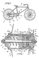
- a first embodiment of apparatus for transmitting power from a rider of a bicycle to the bicycle includes a bicycle frame 20, and a ground engaging wheel 30.
- the ground engaging wheel 30 includes a hub 32 (shown in Fig. 2) and a plurality of wheel spokes 34.
- a shaft 40 is rotatably connected to the frame 20 with both a sprocket 42 and two cranks 44 rigidly connected to the shaft 40.
- Two pedals 46 each of which is connected to one of the cranks 44, may be selectively, drivingly engaged by the rider of the bicycle.
- a motion reversing mechanism includes a figure-eight chain 48.
- the figure-eight chain 48 links the sprocket 42 to a sprocket 90 in a transmission mechanism 50 (shown in Fig. 2) housed in the hub 32 of the ground engaging wheel 30.
- Two idler gears 49 which are spring loaded to take up chain slack, separate the figure-eight chain 48 at a crossover point.
- a rider of the bicycle rotates the shaft 40, as well as the sprocket 42 rigidly mounted on the shaft 40, in a clockwise direction (as viewed in Fig. 1).
- the clockwise rotation of the sprocket 42 produces a clockwise rotation of the portion of the figure-eight chain 48 encircling the sprocket 42.
- the portion of the figure-eight chain encircling the sprocket 90 undergoes a counterclockwise rotation and urges the sprocket 90 to also rotate in the counterclockwise direction.
- the figure-eight chain achieves a motion reversal for the apparatus. That is, as the sprocket 42 rotates in the clockwise direction, the sprocket 90 is made to rotate in the counterclockwise direction.
- the transmission mechanism 50 includes an axle 52 of the wheel 30, which axle is rigid with respect to the frame 20. Encircling the axle 52 is a cylindrical spring 54. A left-hand end of the spring 54 is connected to a left main bearing and spring mount 56, which bearing and spring mount 56 is rigidly mounted on a left-hand portion of the axle 52. The bearing and spring mount 56 is prevented from undergoing a leftward longitudinal motion by a left bearing tension nut 58 and a left lock nut 59, which nuts encircle the axle 52 and are arranged adjacent a left-hand end of the bearing and spring mount 56.
- a pawl mount 60 is rotatably mounted on a right hand portion of the axle 52.
- a right-hand end of the spring 54 is connected to a left-hand portion of the pawl mount 60.
- the pawl mount 60 includes two pawls 62, mounted in circular notches in the pawl mount (see also Fig. 3a).
- the pawls 62 carried by the pawl mount 60 may engage the teeth of a ratchet wheel which is connected to an inner surface of the hub 32.
- the transmission mechanism 50 also includes an engaging mechanism mounted on the shaft 52 which enables a rider of the bicycle to periodically tension the spring 54. That is, the engaging mechanism enables the rider of the bicycle, in conjunction with the reversing mechanism described above, to rotate the pedals 46 in the clockwise direction (as viewed in Fig. 1) while periodically engaging and rotating the pawl mount 60 in the opposite direction, i.e. in the counterclockwise direction. Because the left-hand end of the spring 54 is connected to the bearing and spring mount 56 while the right-hand end of the spring 54 is connected to the pawl mount 60, the counterclockwise rotation of the pawl mount 60 by the engaging mechanism produces a tensioning of the spring 54.
- the spring 54 is thereby periodically tensioned and energy is periodically stored in the spring.
- the spring 54 which has previously been tensioned, is then able to rotate the pawl mount 60 in the clockwise direction.
- the two pawls 62 carried by the pawl mount 60 engage the teeth of the ratchet wheel in the inner surface of the hub 32, thereby transferring the energy previously stored in the spring 54 to the ground engaging wheel 30.
- the engaging mechanism referred to above includes a tubular member 64 which is connected to, and which extends to the right of, the pawl mount 60.
- the engaging mechanism also includes a cam 70 which is rigidly mounted on the axle 52, adjacent to and to the right of the pawl mount 60.
- the cam 70 includes an outer surface having a lefthand portion, denoted by "Left”, and a right-hand portion, denoted by "Right”.
- the pawls 62 are arranged on the pawl mount adjacent the left-hand portion of the outer surface of the cam 70.
- the axially extending tubular member 64 of the pawl mount 60 encircles substantially the whole of the right- hand portion of the outer surface of the cam 70.
- a driver 80 is rotatably mounted on the axle 52 adjacent to, and to the right of, the cam 70.
- the driver 80 includes a tubular member 82 which projects axially to the left, and which encircles the right-hand portion of the outer surface of the cam 70.
- the leftward projecting tubular member 82 is positioned between the outer surface of the cam 70 and an inner surface of the rightwardly extending tubular member 64.
- the leftward projecting tubular member 82 includes a cylindrical wall having apertures which contain ball bearings 84. The ball bearings 84 are in contact with the right- hand portion of the outer surface of the cam 70.
- the sprocket 90 is rigidly mounted on the driver 80.
- One end of the figure-eight chain 48 shown in Fig. 1
- which chain encircles the sprocket 42 also encircles the sprocket 90.
- the ratio of the diameter of the sprocket 90 and driver 80, to the diameter of the sprocket 42 may, for example, be two-to-one.
- the axle 52 is rigidly connected to the frame 20 of the bicycle by conventional means (not shown).
- a left-hand portion of the outer surface of the cam 70 includes two segments, 70a and 70b, each of which segments has a surface with a radius which varies from a first relatively large radius R 1 to a second relatively small radius R 2 .
- Each segment of the left-hand portion of the outer surface of the cam 70 also has a shoulder which defines a juncture between the radius R 1 and the radius R 2 .
- the pawl mount 60 includes two pawls 62, which pawls are pivotably connected to an outer surface of the pawl mount at two points which are diametrically opposed to one another.
- Each of the pawls 62 is urged to pivot into engagement with the teeth of the ratchet wheel connected to the hub 32 by a pawl-biasing spring 66.
- a first end of each of the springs 66 is arranged within a cavity in a lower surface of each of the pawls 62.
- a second end of each of the springs 66 projects through a slot in a cylindrical wall of the pawl mount 60, which cylindrical wall encircles the left-hand portion of the cam 70.
- each of the springs 66 projecting through the cylindrical wall of the pawl mount 60 is mounted on a ball 67.
- Each of the balls 67 rests on the surface of one of the two segments of the outer surface of the left- hand portion of the cam 70.
- a reset spring 68 in the form of a leaf spring, urges each of the pawls 62 to pivot out of engagement with the ratchet wheel in the hub 32.
- a first end of each of the reset springs 68 is arranged between a lower portion of each of the pawls 62 and an outer surface of the pawl mount 60, adjacent one of the points where the pawls 62 are pivotably connected to the pawl mount 60. This first end of each reset spring 68 is connected to an outer surface of the pawl mount 60.
- a second end of each of the reset springs 68 is connected to a lower surface of each of the pawls 62.
- the outer surface of the right-hand portion of the cam 70 includes two concave segments, 70c and 70d, and two convex segments, 70e and 70f. Each concave segment is arranged between the two convex segments.
- the tubular member 82 which member projects axially leftward from the driver 80 (not shown in Fig. 3) to encircle the outer surface of the right-hand portion of the cam 70, carries four ball bearings 84 (denoted by numerals 1, 2, 3 and 4) located in apertures in the cylindrical side wall of the tubular member 82. These apertures in which the ball bearings 84 are located are arranged so that adjacent apertures are ninety degrees from each other. The ball bearings 84 in these apertures are in contact with the outer surface of the right-hand portion of the cam 70.
- the tubular member 64 which projects axially rightward from the pawl mount 60, encircles the tubular member 82.
- the tubular member 64 includes an inner surface having two shoulders, 64a and 64b (see Fig. 4), which two shoulders are positioned one hundred and eighty degrees from each other. The two shoulders in the inner surface of the tubular member 64 may be engaged by the ball bearings 84.
- the first embodiment of apparatus described above operates cyclically as follows.
- one of the pedals 46 is initially assumed to be at about twenty degrees to the vertical. This pedal may be drivingly engaged by a rider of the bicycle and rotated in the clockwise direction through one hundred and eighty degrees. A complete one hundred and eighty degree rotation of one of the pedals 46 constitutes one complete pedal drive cycle.
- the other pedal 46 will have moved into a position at about twenty degrees to the vertical, and it too may then be drivingly engaged and rotated through one hundred and eighty degrees.
- the position of this pedal, as well as the corresponding relative position of the components of the first embodiment of the present invention constitutes a beginning of a pedal drive cycle.
- the resulting position of the pedal 46 and of the components of the first embodiment constitutes a middle of the pedal drive cycle.
- the pedal 46 has been rotated through yet another ninety degrees in the clockwise direction, i.e. after the pedal 46 has been rotated through a full one hundred and eighty degrees, the resulting position of the pedal 46 and of the components of the first embodiment constitutes an end of one pedal drive cycle and the beginning of another.
- a clockwise rotation of one of the pedals 46 produce an identical clockwise rotation of the sprocket 42.
- the pedal 46 and the sprocket 42 rotate through one hundred and eighty degrees in the clockwise direction the figure-eight chain encircling the sprockets 42 and 90 causes the sprocket 90, and the driver 80 (not shown in Fig. 1) on which the sprocket 90 is mounted, to rotate through ninety degrees in the counterclockwise direction. This ninety degree rotation is due to the two-to-one ratio of the diameter of the sprocket 90 to the diameter of the sprocket 42.
- the driver 80 undergoes only half the angular rotation that the pedal 46 and the sprocket 42 undergo, the driver 80 arrives at the middle of. a pedal drive cycle after rotating forty-five degrees in the counterclockwise direction. Similarly, the driver 80 arrives at the end of a pedal drive cycle after rotating an additional forty-five degrees in the counterclockwise direction, i.e. after rotating a total of ninety degrees in the counterclockwise direction.
- the relative positions of the components of the first preferred embodiment of apparatus, at a beginning of a pedal drive cycle, are such that two of the ball bearings 84, denoted by the numerals "1" and “3", are each positioned on a convex segment of the outer surface of the right-hand portion of the cam 70.
- Each of these two ball bearings is in contact with one of the two shoulders in the inner surface of the tubular member 64, which tubular member is connected to the pawl mount 60 (not shown in Fig. 3).
- the two ball bearings denoted by the numerals "2" and "4" are each positioned on a concave segment of the cam 70.
- the position of the pawl mount 60 is such that each of the balls 67, each of which balls carries a pawl biasing spring 66, is positioned on the left-hand portion of the outer surface of the cam 70, at a shoulder which defines the juncture between a segment having a radius R, and a segment having a radius R 2 .
- each of the pawls 62 is too far from the ratchet in the inner surface of the hub 32 for the pawl biasing springs 66 to urge the pawls 67 into engagement with the ratchet teeth.
- the tubular member 82 connected to the driver 80 also begins to rotate in the counterclockwise direction.
- the tubular member 82 begins to rotate in the counterclockwise direction two of the four ball bearings 84 carried by the tubular member 82, and denoted by the numerals "1" and "3", engage the two shoulders in the inner surface of tubular member 64.
- the tubular member 64 is connected to the pawl mount 60 (not shown in Fig. 3) the pawl mount 60 also rotates in the counterclockwise direction.
- the counterclockwise rotation of the pawl mount 60, to which pawl mount the spring 54 is connected produces a tensioning of the cylindrical spring 54.
- each of the balls 67 simultaneously moves in the clockwise direction over the left hand portion of the outer surface of the cam 70.
- This clockwise motion of the balls 67 continues until each of the balls 67 reaches a segment of the lefthand portion of the outer surface of the cam 70 having a radius R 2 . It is in this position, where each of the springs 66 is relatively far from the ratchet wheel in the hub 32, that the springs 66 can no longer bias the pawls 62 to pivot into engagement with the ratchet wheel in the hub 32. Rather, the biasing force exerted by each of the reset springs 68 is now sufficient to pivot each of the pawls 62 out of engagement with the ratchet wheel in the hub 32.
- the operation of the present invention is such that as a rider of the bicycle rotates one of the pedals 46 through one hundred and eighty degrees in the clockwise direction, the driver 80 is rotated through ninety degrees in the counterclockwise direction.
- the driver 80 actuates the engaging mechanism to engage and rotate the pawl mount 60 through forty-five degrees in the counterclockwise direction.
- the cylindrical spring 54 one end of which is connected to the pawl mount 60, is tensioned.
- the engaging mechanism becomes disengaged from the pawl mount 60.
- the tensioned cylindrical spring 54 rotates the pawl mount 60 through forty-five degrees in the clockwise direction.
- the two pawls 62 carried by the pawl mount 60 engage the ratchet wheel in the hub 32 of the ground engaging wheel 30, rotating the wheel 30 in the clockwise direction, thereby propelling the bicycle in the forward direction.
- a second embodiment of apparatus for transmitting power from a rider of a bicycle to the bicycle includes a bicycle frame 100, and a ground engaging wheel 110.
- the ground engaging wheel 110 includes a hub 112 (shown in Fig. 7) and a plurality of wheel spokes 114.
- a shaft 120 is rotatably connected to the frame 100, with both a sprocket 122 and two cranks 124 rigidly connected to the shaft 120.
- Two pedals 126 each of which is connected to one of the cranks 124, may be selectively, drivingly engaged by the rider of the bicycle.
- a transmission chain 128 links the sprocket 122 to a sprocket 162 in a transmission mechanism 130 (shown in Fig. 7) housed in the hub 112 of the ground engaging wheel 110.
- a clockwise rotation of the sprocket 122 also results in a clockwise rotation of the sprocket 162.
- a spring-loaded idler sprocket 129 maintains the transmission chain 128 under tension, and prevents "flyback" when a compressed elastic member, mounted on an axle of the ground engaging wheel 110, is periodically released.
- the transmission mechanism 130 includes an axle 132 of the wheel 110, which axle is rigid with respect to the frame 100. Encircling the axle 132 is a cylindrical spring 134. A left-hand end of the spring 134 is mounted in a semi-circular notch in a right- hand end of a bearing and spring mount 136, which bearing and spring mount 136 is mounted on a left-hand portion of the axle 132. As shown in Fig. 16, a tip of the left-hand end of the spring 134 mounted in the semi-circular notch in the right-hand end of the bearing and spring mount 136 abuts against an end wall of the semi-circular notch. Thus when a right-hand end of the spring 134 is rotated in a counterclockwise direction (as viewed from the right in Fig. 7) the left-hand end of the spring 134 is held stationary.
- a spring tension adjustment gear 138 is mounted on the bearing and main spring mount 136.
- the bearing and main spring mount 136 is prevented from undergoing a leftward longitudinal motion by a left bearing tension nut 140, which nut encircles a threaded portion of the axle 132 and is arranged adjacent a left-hand end of the bearing and spring mount 136.
- a cam 142 hereinafter referred to as the clutch cam, is rotatably mounted on a right-hand portion of the axle 132.
- a righthand end of the spring 134 is mounted in a semi-circular notch in a left- hand portion of the clutch cam 142.
- a tip of the right-hand end of the spring 134 mounted in the semi-circular notch in the left-hand portion of the clutch cam 142 abuts against an end wall of this semi-circular notch.
- this end wall in the semi-circular notch is also rotated in the counterclockwise direction. Because the tip of the right-hand end of the spring 134 abuts against this end wall, it follows that the right-hand end of the spring 134 will also be rotated in the counterclockwise direction.
- an outer surface of the clutch cam 142 which outer surface is substantially circular, includes four recesses, or notches, each of which recesses contains a roller 144.
- These recesses are substantially triangular in cross section, i.e., they each include a wide portion which gradually merges into a narrow portion.
- Each of the recesses also contains a tension spring 145, one end of which spring is arranged in a cylindrical aperture in the wall of the recess, and another end of which is in contact with the roller 144.
- the rollers 144 are hereinafter referred to as the clutch cam rollers.
- the clutch cam rollers may frictionally engage an inner surface of the hub 112.
- two pins 143a and 143b rigidly connected to a right-hand end of the clutch cam 142, project to the right from the clutch cam 142.
- the pins 143a and 143b are one hundred and eighty degrees apart from one another, and are arranged radially inward relative to the semi-circular notch in the left-hand portion of the clutch cam 142.
- the transmission mechanism 130 also includes a reversing mechanism and an engaging mechanism, both of which mechanisms are mounted on the axle 132, and which mechanisms enable a rider of the bicycle to periodically tension the spring 134. That is, the reversing and engaging mechanisms enable the rider of the bicycle to rotate the pedals 126 in the clockwise direction (as viewed in Fig. 6) while periodically engaging and rotating the clutch cam 142 in the opposite direction, i.e. in the counterclockwise direction.
- the counterclockwise rotation of the clutch cam 142 by the reversing and engaging mechanisms produces a tensioning of the spring 134.
- the spring 134 is thereby periodically tensioned and energy is periodically stored in the spring.
- the clutch cam 142 is periodically freed by the engaging mechanism, the spring 134, which has previously been tensioned, is then able to rotate the clutch cam 142 in the clockwise direction.
- the four clutch cam rollers 144 carried by the clutch cam 142 frictionally engage the inner surface of the hub 112 thereby transferring the energy previously stored in the spring 134 to the ground engaging wheel 110.
- the engaging mechanism referred to above includes a tubular member 146 projecting from the clutch cam 142.
- the tubular member 146 projects to the right of the clutch cam 142.
- the tubular member 146 contains two longitudinal recesses, which recesses are approximately one hundred and eighty degrees apart from one another.
- Each of the recesses in the tubular member 146 contains a roller 147.
- the rollers 147 are hereinafter referred to as the driver cam rollers.
- a cam 148 is rigidly mounted on the axle 132, adjacent to and to the right of the clutch cam 142.
- the cam 148 is hereinafter referred to as the driver cam.
- the driver cam 148 is rigidly mounted on the axle 132 by means of a key 149.
- the driver cam 148 includes an outer surface which is substantially circular.
- the outer surface of the driver cam 148 includes two recesses, or notches, which recesses are approximately one hundred and eighty degrees apart from one another.
- the outer surface of the driver cam 148 is encircled by the tubular member 146 projecting from the clutch cam 142.
- the driver cam rollers 147 carried by the tubular member 146, ride over the outer surface of the driver cam 148.
- a right-hand end of the driver cam 148 contains three equiangularly spaced longitudinal apertures. Each of these longitudinal apertures contains a pin 150. Each of the pins 150 projects to the right of the driver cam 148. Mounted on each of the pins 150 is a planet gear 152.
- a left- hand end of the driver cam 148 is provided with two circular slots 151 a and 151 b. Each of these slots is arranged adjacent one of the recesses or notches in the outer surface of the driver cam 148, and each of the slots subtends an angle of forty-five degrees.
- the pin 143a projecting from the righthand end of the clutch cam 142 projects into an interior of the slot 151 a, while the pin 143b projects into an interior of the slot 151 b.
- An initial relative position of the clutch 142 and the driver cam 148 is such that the pin 143a initially abuts against a right-hand end of the slot 151 a (as viewed in Fig.
- the reversing mechanism referred to above includes a nut 164, which nut encircles a right-hand, threaded portion of the axle 132.
- Rotatably mounted on the nut 164 is a sprocket mount 154.
- a tubular member 155 which tubular member is connected to the sprocket mount 154, projects to the left from the sprocket mount 154.
- the tubular member 155 encircles the axle 132 and is arranged between the driver cam 148 and the sprocket mount 154.
- Mounted on the tubular member 155 is a sun gear 156.
- the teeth of the sun gear 156 may engage the teeth of the three planet gears 152, each of which planet gears is mounted on one of the pins 150 projecting from the driver cam 148 (not shown in Fig. 8).
- a ring gear 158 is rotatably mounted on the sprocket mount 154. As shown in Fig. 8, the teeth of the three planet gears 152 may engage the teeth of the ring gear 158. As shown in Fig. 7, connected to the ring gear 158, and projecting to the shaft from the ring gear 158, is a tubular member 160. This tubular member 160 is hereinafter referred to as the cam driver. As shown in Fig. 8a, the cam driver 160, which is a component of the engaging mechanism, encircles the driver cam 148 as well as the driver cam rollers 147, which rollers roll over the outer surface of the driver cam 148. An inner surface of the cam driver 160 includes four shoulders which are spaced ninety degrees apart from one other. The shoulders in the inner surface of the cam driver 160 may engage the driver cam rollers 147.
- the sprocket 162 is rigidly mounted on the sprocket mount 154.
- the sprocket mount 154 includes a tubular member 155.
- the sun gear 156 is mounted on the tubular member 155, and this sun gear has teeth which mesh with those of the planet gears 152.
- the planet gears 152 have teeth which mesh with those of the ring gear 158.
- a clockwise rotation of the sprocket 122 results in a counterclockwise rotation of the ring gear 158.
- the dimensions of the sprockets 122 and 162, and the dimensions of the gears 156, 152, and 158 may be such as to produce an equivalent static gear ratio of two-to-one. That is, the dimensions of the above noted members may be such that a one hundred and eighty degree clockwise rotation of the sprocket 122 produces a ninety degree counterclockwise rotation of the ring gear 158.
- axle 132 is rigidly connected to the frame 100 of the bicycle by conventional means (not shown).
- the second embodiment of apparatus described above operates cyclically as follows.
- one of the pedals 126 is initially assumed to be at about twenty degrees to the vertical. This pedal may be drivingly engaged by a rider of the bicycle and rotated in the clockwise direction through one hundred and eighty degrees. A complete one hundred and eighty degree rotation of one of the pedals 126 constitutes one complete pedal drive cycle.
- the other pedal 126 will have moved into a position at about twenty degrees to the vertical, and it too may then be drivingly engaged and rotated through one hundred and eighty degrees.
- the position of this pedal constitutes a beginning of a pedal drive cycle.
- the resulting position of the pedal 126 and of the components of the second embodiment constitutes a middle of the pedal drive cycle.
- the pedal 126 has been rotated through yet another ninety degrees in the clockwise direction, i.e. after the pedal 126 has been rotated through a full one hundred and eighty degrees, the resulting position of the pedal 126 and of the components of the second embodiment constitutes an end of one pedal drive cycle and the beginning of another.
- a clockwise rotation of one of the pedals 126 produces an identical clockwise rotation of the sprocket 122.
- the transmission chain 128, encircling sprockets 122 and 162 causes the sprocket 162 and the sprocket mount 154 (not shown in Fig. 6), on which the sprocket 162 is mounted, to also rotate in the clockwise direction.
- the clockwise rotation of the sprocket mount 154 (not shown in Figs. 8 and 9) produces an identical rotation of the tubular member 155, which tubular member is connected to the sprocket mount 154.
- Mounted on the tubular member 155 is the sun gear 156, which undergoes an identical clockwise motion.
- the sun gear 156 rotates in the clockwise direction
- the teeth of the sun gear mesh with the teeth of the planet gears 152, causing the planet gears to rotate in the opposite direction, i.e. in a counterclockwise direction.
- the teeth of the planet gears 152 in turn mesh with the teeth of the ring gear 158 causing the ring gear, in turn, to rotate in the counterclockwise direction.
- the cam driver 160 (not shown in Fig. 8 or Fig. 9), which is connected to the ring gear 158, also rotates in the counterclockwise direction. Because there is an equivalent static gear ratio of two-to-one between the sprocket 162 and gears 156, 152, and 158, and the sprocket 122, it follows that a one hundred and eighty degree clockwise rotation of the sprocket 122 results in a ninety degree counterclockwise rotation of the ring gear 158 and the cam driver 160.
- the ring gear 158 and cam driver 160 undergo (in the counterclockwise direction) only half the (clockwise) angular rotation that the pedal 126 and sprocket 122 undergo, the ring gear 158 and cam driver 160 arrive at the middle of a pedal drive cycle after rotating only forty-five degrees in the counterclockwise direction. Similarly, the ring gear 158 and cam driver 160 arrive at the end of a pedal drive cycle after rotating a total of ninety degrees in the counterclockwise direction.
- each of the driver cam rollers 147 is positioned on a circular portion of the outer surface of the driver cam 148.
- Each of the driver cam rollers 147 is denoted either by a numeral "1" or a numeral "2".
- the driver cam rollers 147 are one hundred and eighty degrees apart from one another, and each is forty-five degrees away from a nearby slot, or recess, in the outer surface of the driver cam 148. Two of the shoulders in the inner surface of the cam driver 160 are in contact with the two driver cam rollers 147.
- the pin 143a projecting into the interior of the slot 151 a abuts against a right- hand end of the slot 151 a, while the pin 143b projecting into the interior of the slot 151 b, abuts against a lefthand end of the slot 151b.
- the counterclockwise rotation of the clutch cam 142 results in the pins 143a and 143b being rotated in the counterclockwise direction through the interiors of the slots 151 a and 151 b, respectively.
- the counterclockwise rotation of the clutch cam 142 also results in a tensioning of the spring 134.
- the counterclockwise rotation of the driver cam rollers 147 proceeds until each of the rollers falls into a recess in the outer surface of the driver cam 148. Upon falling into these recesses, the driver cam rollers 147 become disengaged from the cam driver 160.
- the disengagement of the driver cam rollers 147 from the cam driver 160 occurs after the driver cam rollers 147 have rolled forty-five degrees in the counterclockwise direction, over the outer surface of the driver cam 148.
- the moment of disengagement of the driver cam rollers 147 from the cam driver 160 is the middle of a pedal drive cycle.
- the clutch cam 142 (shown in Fig. 10b) is rotated in the clockwise direction under the influence of the tensioned spring 134.
- the clockwise rotation of the clutch cam 142 results in the pins 143a and 143b being rotated in the clockwise direction through the interiors of the slots 151 a and 151b, respectively.
- the clutch cam rollers 144 carried in recesses in the outer surface of the clutch cam 142, roll from the wider to the narrower portions of their recesses and frictionally engage the inner surface of the hub 112, causing the hub to rotate in the clockwise direction.
- the clockwise rotation of the clutch cam 142 results in a corresponding clockwise rotation of the tubular member 146, which tubular member is connected to the clutch cam 142.
- the clockwise rotation of the tubular member 146 in turn results in a corresponding clockwise rotation of the driver cam rollers 147 over the outer surface of the driver cam 148, which rollers are carried in longitudinal recesses in the tubular member 146.
- the driver cam rollers 147 After the driver cam rollers 147 have rotated forty-five degrees in the clockwise direction over the outer surface of the driver cam 148, the driver cam rollers 147 come into contact with the two shoulders in the inner surface of the cam driver 160 which had not previously engaged the driver cam rollers 147. It is to be noted that the cam driver 160 continues to rotate in the counterclockwise direction throughout the entire pedal drive cycle.
- An end of the pedal drive cycle occurs at the instant that the two driver cam rollers come into contact with the two shoulders in the inner surface of the cam driver 160, which shoulders had not previously engaged the driver cam rollers 147. This occurs after the cam driver has rotated a total of ninety degrees in the counterclockwise direction.
- the spring 134 has rotated the clutch cam 142 through forty-five degrees in a clockwise direction. During this clockwise rotation of the clutch cam 142 the spring 134 gives up all of the energy stored in the spring during the interval between the beginning of the pedal drive cycle and the middle of the pedal drive cycle.
- the operation of the second embodiment is such that a clockwise rotation of one of the pedals 126 produces a clockwise rotation of the sprockets 122 and 162.
- the sprocket mount 154 which carries the sprocket 162 also rotates in the clockwise direction.
- the sun gear 156 which is mounted on the tubular member 155 connected to the sprocket mount 154, also rotates in the clockwise direction (as viewed in Fig. 9). But, as shown in Fig.
- a counterclockwise rotation of the ring gear 158 produces an identical counterclockwise rotation of the cam driver 160, (as viewed in Fig. 9a), which cam driver is connected to the ring gear 158.
- the cam driver 160 rotates in the counterclockwise direction, two of the four internal shoulders in the inner surface of the cam driver 160 engage the two driver cam rollers 147, which rollers roll over the surface of the driver cam 148, and which rollers are carried by the tubular member 146.
- the tubular member 146 is thereby also forced to rotate in the counterclockwise direction. Because the tubular member 146 is connected to the clutch cam 142 (not shown in Fig. 9a), and because a right-hand end of the spring 134 is mounted in a semi-circular notch in the clutch cam 142, the clutch cam 142 is rotated in the counterclockwise direction and the spring 134 is thereby tensioned.
- a rider of the bicycle may adjust the transmission mechanism 130 to suit his own power speed characteristics by precompressing the spring 134.
- This precompression may be accomplished by rotating the main spring tension adjustment gear 138 in a counterclockwise direction.
- the main spring tension adjustment gear 138 is rigidly mounted on the bearing and main spring mount 136, which spring mount includes a right-hand portion (as seen from Fig. 7) having a semi-circular notch. A left-hand portion of the spring 134 is embedded in this semi-circular notch.
- the rotation of the main spring tension adjustment gear 138 may be accomplished by turning a worm gear 139, whose teeth mesh with the teeth of the mainspring tension adjustment gear 138.
- the spring 134 may be precompressed by rotating the main spring tension adjustment gear 138 in a counterclockwise direction, while the spring 134 may be relaxed by rotating the main spring tension adjustment gear 138 in a clockwise direction.
- the main spring tension adjustment gear 138 may be rotated in a clockwise or counterclockwise direction by rotating the worm gear 139 in either a clockwise or counterclockwise direction.
- the pins 143a and 143b projecting from the right-hand end of the clutch cam 142 into the interiors of the circular slots 151 a and 151 b, respectively, in the left-hand end of the driver cam 148, permit the clutch cam 142 to rotate in a counterclockwise direction at the beginning of a pedal drive cycle, but prevent the clutch cam 142 from rotating in a clockwise direction at the beginning of a pedal drive cycle.
- This feature permits a precompression of the spring 134 to be maintained in the absence of any rotation of the pedals 126.
- a third embodiment of apparatus for transmitting power from a rider of a bicycle to the bicycle is similar to the second embodiment but differs in that a motion reversing mechanism 230 is housed in a pedal hub 226 (shown in Fig. 13) near the front of the bicycle, while an engaging mechanism is housed in a hub 254 (shown in Fig. 12) of a ground engaging wheel 210 near the rear of the bicycle.
- the third embodiment like the second embodiment, includes a bicycle frame 200, and a ground engaging wheel 210.
- the ground engaging wheel 210 includes a hub 254 and a plurality of wheel spokes 214.
- a shaft 220 is rotatably connected to the frame 200.
- Cranks 222 are rigidly connected to threaded portions of the shaft 220, and pedals 224 are connected to the cranks 222.
- the pedals 224 may be selectively, drivingly engaged by the rider of the bicycle.
- a pedal hub 226 encircles the shaft 220 and is rigidly connected to the frame 200.
- the pedal hub 226 houses the motion reversing mechanism 230, as well as a first sprocket 248.
- a transmission chain 250 links the first sprocket 248 to a second sprocket 286 in a mechanism 260 housed in the hub 254 of the ground engaging wheel 210.
- the mechanism 260 includes an engaging mechanism for periodically compressing an elastic element, as well as a oneway clutch.
- a spring loaded idler gear 252 maintains the transmission chain 250 under tension to prevent "flyback" when the elastic element is released after having been compressed.
- the motion reversing mechanism 230 includes a hub mount 231 which encircles a lefthand, threaded portion of the shaft 220.
- the hub mount 231 is mounted on the shaft 220 adjacent to, but to the right of, one of the cranks 222.
- An annular member 232 which is to the right of, and spaced apart from, the hub mount 231, encircles the shaft 220 and is rigidly connected to the pedal hub 226 by a screw 234.
- the annular member 232 is hereinafter referred to as the planet gear mount.
- the planet gear mount 232 includes three equiangularly spaced longitudinal apertures. Each of the longitudinal apertures contains a pin 236 which projects to the right from the planet gear mount 232. Rotatably mounted on each of the pins 236 is a planet gear 238.
- a sun gear 240 is rigidly mounted on the shaft 220 adjacent to, and to the right of, the planet gear mount 232.
- the teeth of the sun gear 240 mesh with the teeth of the planet gears 238.
- a nut 242 Rigidly mounted on a right-hand, threaded portion of the shaft 220 is a nut 242.
- a first sprocket mount 244 Connected to the sprocket mount 244, and projecting to the left from the sprocket mount 244, is a ring gear 246.
- the teeth of the planet gears 238 mesh with the teeth of the ring gear 246.
- the first sprocket 248 is rigidly mounted on the sprocket mount 244.
- the transmission chain 250 encircles the first sprocket 248 and links the first sprocket 248 to the second sprocket 286 in the mechanism 260 housed in the hub 254 of the ground engaging wheel 210.
- the mechanism 260 includes an axle 262 of the wheel 210, which axle is rigid with respect to the frame 200. Encircling the axle 262 is a cylindrical spring 264. Mounted on a left-hand portion of the axle 262 is a bearing and main spring mount 266. A right-hand portion of the bearing and spring mount 266 includes a semi-circular notch. As was the case with the second embodiment, a left-hand portion of the cylindrical spring 264 is embedded in this semicircular notch. Rigidly mounted on the bearing and main spring mount 266 is a main spring tension adjustment gear 268. Mounted on an extreme, left-hand, threaded portion of the axle 262 is a nut 270. The nut 270 prevents the bearing and main spring mount 266 from undergoing a leftward, longitudinal motion.
- the clutch cam 272 Rotatably mounted on a right-hand portion of the axle 262 is a cam 272.
- This cam 272 is hereinafter referred to as the clutch cam.
- the clutch cam 272 includes a lefthand end which contains a semi-circular notch.
- a righthand portion of the cylindrical spring 264 is mounted in this semi-circular notch.
- the clutch cam 272 includes a substantially cylindrical outer surface. This outer surface includes four equi-angularly spaced notches, or recesses. Each of these notches, or recesses, contains a roller 274.
- the rollers 274 are hereinafter referred to as the clutch cam rollers. The clutch cam rollers 274 may frictionally engage an inner surface of the hub 254.
- the tubular member 276 Projecting from a right-hand end of the clutch cam 272, and connected to the clutch cam 272, is a tubular member 276.
- the tubular member 276 contains two longitudinal recesses which are one hundred and eighty degrees apart from one another. Each of the longitudinal recesses contains a roller 277.
- the two rollers 277 are hereinafter referred to as the driver cam rollers.
- the cam 278 Rigidly mounted on the axle 262, adjacent to and to the right of the clutch cam 272, is a cam 278.
- the cam 278 is hereinafter referred to as the driver cam.
- the driver cam 278 is rigidly connected to the axle 262 by a key 279.
- the driver cam 278 includes an outer surface which is substantially cylindrical in shape.
- the outer surface of the driver cam 278 includes two notches, or recesses, which are spaced apart from one another by one hundred and eighty degrees.
- the driver cam rollers 277, carried by the tubular member 276, are in contact with the outer surface of the driver cam 278.
- the tubular member 284 is hereinafter referred to as the cam driver.
- the cam driver 284 includes an inner surface having four equiangularly spaced shoulders. These four shoulders may engage the driver cam rollers 277.
- the sprocket 286 is rigidly mounted on the second sprocket mount 282.
- the second sprocket 286 is linked to the first sprocket 248 by the transmission chain 250, which transmission chain encircles both sprockets.
- the axle 262 is rigidly connected to the frame 200 of the bicycle by conventional means (not shown).
- the third embodiment of apparatus also includes a mechanism for pretensioning the spring 264.
- This mechanism includes a main spring tension adjustment gear 268 mounted on the bearing and main spring mount 266.
- a worm gear whose teeth mesh with those of the spring tension adjustment gear 268, like the worm gear in Fig. 15, may be used to rotate the gear 268 in a clockwise or counterclockwise direction in order to relax or to pretension the spring 264.
- the third embodiment like the second embodiment, also includes two pins 243a and 243b connected to a right-hand end of the clutch cam 272, and two circular slots in a left- hand end of the driver cam 278.
- Each of the slots subtends an angle of forty-five degrees, and each of the pins projects into an interior of one of the slots.
- the slots permit the pins and the clutch cam 272 to rotate in a counterclockwise direction (as viewed from the right in Fig. 12) at the beginning of a pedal drive cycle, but prevent the clutch cam 272 from rotating in a clockwise direction at the beginning of a pedal drive cycle.
- a precompression of the spring 264 may be maintained in the absence of any rotation of the pedals 224.
- the third embodiment of apparatus described above operates in a fashion quite similar to that of the second embodiment.
- the one major difference in the operations of the second and third embodiments is that, with respect to the third embodiment, a clockwise motion of the pedals 224 is transformed into a counterclockwise motion of the sprocket 248 by the motion reversing mechanism 230 housed in the pedal hub 226.
- the mechanism 260 housed in the hub 254 of the ground engaging wheel 210, then produces a periodic tensioning of the cylindrical spring 264, and a periodic transfer of the energy periodically stored in the spring 264 to the hub 254.
- the dimensions of the sprockets 286 and 248 and gears 240, 238, and 246, are such that a one hundred and eighty degree clockwise rotation of the pedals 224 and the shaft 220 results in a ninety degree counterclockwise rotation of the sprocket 286.
- the transmission apparatus of the present invention has a number of advantages.
- One such advantage is due to the use of a spring for storing energy because a spring can accept power from a rider of a bicycle at one speed while efficiently delivering power to a ground engaging wheel of the bicycle over a broad range of speeds. That is, as the rider rotates the pedals of the bicycle at a first speed, the cylindrical spring becomes linked to the pedals, and receives and stored energy from the rotating pedals, during a first portion of the pedal drive cycle. During a second portion of the pedal drive cycle the cylindrical spring becomes disengaged from the pedals and engages the ground engaging wheel of the bicycle through the free-wheeling clutch.
- the cylindrical spring relaxes and transfers its stored energy to the ground engaging wheel, which wheel may be rotating at a second speed that may be quite different from the first speed of the pedals.
- Another advantage of the present invention is that a rider of a bicycle is decoupled from a load on the bicycle. This is due to the fact that the rider is never directly linked to the ground engaging wheel of the bicycle, but is only indirectly linked through the energy-storing spring. Thus, as the terrain becomes steeper and the load on the bicycle correspondingly increases, the rider does not feel this increase in the load. The rider may continue to deliver whatever constant power he wishes to deliver to the bicycle, and the bicycle will continue to move in a forward direction. However, the speed of the bicycle will decrease as the terrain becomes steeper, and eventually the terrain may become so steep that the constant power delivered by the rider is no longer sufficient to propel the bicycle in the forward direction.
- Yet a further advantage of the present invention is that it is, in a sense, an automatic transmission. That is, with the present invention, a rider of a bicycle producing an average power need not shift through a plurality of gear combinations, as the speed of the bicycle changes, to transmit all of this average power to the bicycle, as is necessary with a conventional multi-geared bicycle. This is explained in more detail below.
- FIG. 17 A qualitative plot of a torque delivered to a ground engaging wheel of a bicycle incorporating the present invention, as a function of time during a pedal drive cycle, when a rider of the bicycle is producing power at a constant pedal speed, is provided in Fig. 17.
- a rider of a bicycle produces power at a constant pedal speed
- the torque delivered to the ground engaging wheel of the bicycle by the elastic element of the present invention is zero during a first portion of the pedal drive cycle, increases to a maximum at the beginning of a second portion of the pedal drive cycle, and then decreases from this maximum to zero during the second portion of the pedal drive cycle.
- An average torque, T, delivered to the ground engaging wheel during a complete pedal drive cycle is that torque whose amplitude, multiplied by a length in time of a complete pedal drive cycle, is equal to an area under the torque versus time curve of the second portion of the pedal drive cycle.
- FIG. 18 A qualitative plot of the average torque delivered to a ground engaging wheel of a bicycle incorporating the present invention, when a rider of the bicycle is producing power at a constant pedal speed, is provided in Fig. 18.
- the average torque, T delivered by the present invention to the ground engaging wheel of a bicycle, decreases from a maximum, called the stall torque, is, when a speed of the bicycle, v b , is zero, toward zero as the speed of the bicycle increases.
- the average power, P, delivered by the present invention to the ground engaging wheel of a bicycle ridden by a rider producing power at a constant pedal speed is defined to be the multiple of the average torque, T, and the bicycle speed, v bt i.e. then the average power delivered by the present invention to the ground engaging wheel of the bicycle is as shown in Fig. 19. That is, the average power quickly increases from zero, at zero bicycle speed, to a constant value above a minimum bicycle speed, v bmtn . This constant value is just the average constant power produced by the rider of the bicycle.
- the present invention acts like an ideal transmission, i.e., it transmits to the bicycle virtually all the power produced by the rider.
- VbmaX' which is typically many times the size of the minimum bicycle speed, v bmin , however, the present invention no longer acts like an ideal transmission.
- FIG. 20 A qualitative plot of a power delivered to a ground engaging wheel of a bicycle as a .function of bicycle speed, by each individual gear combination of a multi-geared conventional bicycle transmission, is provided in Fig. 20.
- the power produced by a rider of the bicycle substantially all of which power is delivered by each gear combination of the bicycle transmission to the bicycle, varies sharply with bicycle speed. That is, each individual gear combination transmits to the bicycle substantially all of the maximum power delivered by a rider of the bicycle, only over a very narrow bicycle speed range.
- the present invention acts like an ideal transmission only if there is sufficient time for the energy-storing spring to be cocked and completely uncocked. That is, there must be sufficient time for the spring to fully relax before being cocked again.
- v bmin the ground engaging wheel is rotating so slowly, i.e. the spring is being uncocked so slowly, that the spring will be cocked again before it has completely relaxed.
- V bma an angular inertia of the spring prevents the spring from relaxing quickly enough to give up all of its stored energy to the very rapidly rotating ground engaging wheel of the bicycle.
- V bmln may be less than about five kilometers per hour, while v bmax may be in excess of about 500 kilometers per hour.
- the present invention may act like an ideal transmission for a speed ratio, i . e ., a ratio of v bmax to Vbmin' of about one hundred.
- the stall torque, as, delivered to a bicycle by the present invention is much higher than the stall torque delivered by a transmission of a conventional bicycle.
- the stall torque is proportional to a multiple of three factors: the rider's weight; the ratio of the pedal radius to the radius of the ground engaging wheel; and the static gear ratio. That is, where: W r is the rider's weight; Rp is the pedal radius; R w is the radius of the ground engaging wheel; and G r is the static gear ratio.
- W r is the rider's weight
- Rp is the pedal radius
- R w is the radius of the ground engaging wheel
- G r is the static gear ratio.
- the static gear ratio or the equivalent static gear ratio is two-to-one.
- the preferred embodiments of the present invention are able to deliver a stall torque which is four times greater than the stall torque that a conventional transmission of a conventional bicycle is able to deliver.
- the stall torque is the largest torque which can be delivered to a bicycle.
- the magnitude of the stall torque is important because it determines, in effect, the steepest terrain which can be surmounted by the bicycle. That is, as the stall torque increases, the force that propels the bicycle at zero speed increases. As this force increases, the steepness of the terrain which may be surmounted by a bicycle increases.
- the present invention delivers a much greater stall torque to a bicycle than a conventional transmission, the present invention enables a rider-propelled bicycle to rider over more steeply inclined terrain than is possible with a conventional bicycle.
- the large magnitude of the stall torque produced by the present invention is also advantageous because it implies that the acceleration which a bicycle will experience at low speeds is relatively high. The greater this acceleration the more quickly the bicycle will achieve a speed at which the present invention acts as an ideal transmission.
- a conventional, multi-geared bicycle may be modified to include a two-to-one gear combination at low speeds in order to increase the deliverable stall torque.
- the advantage gained by such a modification is offset by the relatively poor power-bicycle speed characteristics of the different gear combinations of a conventional bicycle, including the two-to-one gear combination, as shown in Fig. 20.
- the rider of a conventional bicycle would have to start shifting gears almost immediately in order to transmit effectively constant power to the bicycle.
Abstract
Description
- The invention disclosed herein pertains generally to transmission mechanisms, and more particularly to a transmission mechanism for a bicycle.
- It is known in the bicycle art to transmit the power delivered by a rider to the pedals of a bicycle to a ground engaging wheel of the bicycle by the use of gears and shifting mechanisms. It is also known that high performance bicycles often have transmission mechanisms which include 10 to 15 different gear ratios and a derailleur mechanism which mechanically moves a chain from one gear combination to another. The purpose of these gears and shifting mechanisms is to enable the rider to rotate the pedals of the bicycle at whatever speed he chooses, but particularly to enable the rider to rotate the pedals over a relatively narrow pedal speed range. That is, the purpose of the gears and shifting mechanisms is to enable the rider to deliver power to the bicycle over a narrow pedal speed range, while the ground engaging wheel rotates over a much wider speed range. The reason for this is that the power that a human rider can generate varies sharply with pedal speed, i.e. the power pedal speed curve of a human rider is sharply peaked. Thus, the gears and shifting mechanisms enable the rider to rotate the pedals over the relatively narrow pedal speed range at which the rider can deliver the maximum power which he can generate. The greater the number of gears and gear ratios, the greater the bicycle speed range over which the rider may continue to deliver effectively constant power to the ground engaging wheel while rotating the pedals at an almost constant pedal speed.
- The use of intermittently tensioned springs for transmitting power to a ground engaging wheel of a bicycle, or for retracting the pedals of a bicycle, is also known in the bicycle art. For example, U.S. Patent No. 4,108,459 issued to Alvigini, and U.S. Patent No. 524,652 issued to Risinger, disclose bicycle transmission mechanisms which include springs that are intermittently tensioned by a bicycle rider, and which springs either continuously deliver power to a ground engaging wheel of a bicycle, or are used to retract the pedals of a bicycle which have been depressed from a first position to a second position.
- The Alvigini patent (No. 4,108,459) discloses a spring powered bicycle. This bicycle includes a spring drum which is incorporated in a ground engaging wheel of the bicycle. The bicycle also includes a drive shaft on which the spring drum is rotatably mounted. Contained within the spring drum is a spiral spring, an inner end of which is connected to the drive shaft and an outer end of which is connected to an outer periphery of the spring drum. A free wheeling clutch is mounted on the outside face of the spring drum and has a matching section on an inside face of the ground engaging wheel.
- In the Alvigini device, two shafts are rotatably mounted on the bicycle. A lever is rigidly connected to each of the shafts and a pedal is connected to each lever. The rotatable shafts are linked to the drive shaft by a oneway clutch, a set of gears, a pair of sprocket wheels, and a transmission chain. Thus when the pedals are depressed, the spiral spring is wound up. But as the spiral spring winds up it also continuously unwinds on its outer end, causing the spring drum to rotate, thereby rotating the ground engaging wheel.
- The Risinger patent (No. 524,652) discloses a bicycle which includes an eccentric spring drum, and which spring drum is rotatably mounted on an axle of the bicycle. Contained within the spring drum is a cylindrical spring, a first end of which spring is connected to the spring drum and a second end of which spring is connected to the axle. The spring drum includes a ratchet portion which engages a series of wedges connected to a hub of the bicycle. The ratchet portion engages the wedges through a series of rollers. A first end of a steel strip is wound about the spring drum and a second end is connected to a set of levers, which levers may be oscillated by depressing a set of pedals connected to the levers. In use, a rider depresses the pedals, thereby rotating the spring drum in a forward direction while simultaneously tensioning the cylindrical spring. As the spring drum rotates in the forward direction, the ratchet portion engages the wedges connected to the hub, causing the hub to rotate in the forward direction. After a completion of a pedal downstroke, the spring drum is rotated in a backward direction under the influence of the tensioned cylindrical spring, causing the pedals to return to their original position.
- U.S. Patent 2,908,356 (Daarud) also discloses a spring drive for a bicycle in which a power drum housing a coiled spring is mounted at the bottom of the frame. The spring is connected to the drive sprocket and can be tensioned by rotation of the pedals. An actuating lever on the cross-bar is linked to means for locking and unlocking the drum so that power can be stored by the coiling of the spring and released to assist driving of the wheels as desired various transmission mechanisms which may be used in bicycles are also disclosed in the following patents: U.S. Patent No. 96,963 issued to Repetti; U.S. Patent No. 2,638,359 issued to Crumble; U.S. Patent No. 1,612,739 issued to Matsumoto; U.S. Patent No. 3,734,535 issued to Sidlauskas; U.S. Patent No. 4,119,182 issued to Steuer; U.S. Patent No. 3,648,809 issued to Schwerdhofer; U.S. Patent No. 3,720,294 issued to Plamper; U.S. Patent No. 88,238 issued to Van Anden; U.S. Patent No. 628,249 issued to Kane; British Patent No. 2460 issued to Brereton et al; U.S. Patent No. 670,608 issued to Dennis; and U.S. Patent No. 538,324 issued to De Graff.
- An ideal bicycle transmission mechanism is one which transmits to the bicycle all the power delivered by a rider of the bicycle, regardless of the bicycle speed. That is, an ideal transmission is one wherein a rider of a bicycle may choose the power which he wishes to deliver to the bicycle by rotating the pedals at a speed which corresponds to this power, and the ideal transmission will deliver all of this power to the ground engaging wheel of the bicycle. The ground engaging wheel of the bicycle may, of course, be rotating at a speed quite different from that of the pedals, and this speed may vary over a wide range. The known prior art bicycle transmission mechanisms which employ gears and shifting mechanisms are not entirely satisfactory as ideal transmission mechanisms because they tend to be cumbersome, require appreciable time for shifting, and require almost continuous shifting under rapidly varying road conditions. More importantly, these known transmission mechanisms represent only approximations to the ideal transmission mechanism because they provide only a finite number of discrete gear ratios rather than a continuous spectrum of gear ratios.
- Accordingly, a primary object of the present invention is to provide a method and apparatus which more nearly approximates an ideal transmission mechanism.
- The invention provides a method of transmitting power from a rotatable driving member to a rotatable driven member, in which energy is stored in an energy storage means which energy is transmitted selectively from the energy storage means to the driven member, characterized by alternatively and repeatedly first linking the driving member to the energy storage means and then linking the energy storage means to the driven member in order to transfer energy successively and repeatedly from the driving member to the energy storage means and from the energy storage means to the driven member, decoupling the driving member from the energy storage means while the energy storage means is linked to the driven member, and decoupling the driven member from the energy storage means while the energy storage means is linked to the driving member.
- Further the invention provides apparatus for transmitting power from a rotatable driving member to a rotatable driven member including energy storage means for storing mechanical energy for transmission to the driven member, characterised by transmission means for alternately and repeatedly first linking the driving member to the energy storage means and then linking the energy storage means to the driven member to transmit substantially all the power from the driving member to the driven member while the driving member and the driven member rotate, means for decoupling the driving member from the energy storage means while the energy storage means is linked to the driven member, and means for decoupling the driven member from the energy storage means while the energy storage means is linked to the driving member.
- The apparatus is particularly for transmitting power from a driving device or power source, such as a rider of a bicycle, to a driven device, such as a ground engaging wheel of a bicycle in which an elastic element, such as a spring, stores energy delivered by the driving device to the driver member, a reversing mechanism transmits, in reverse, a rotational motion of the driving device to the elastic element in order to cock the elastic element, and a mechanism allows the driving device to periodically compress and release the elastic element. The preferred apparatus also includes a free-wheeling clutch, i.e. an overriding clutch, which intermittently transmits the energy stored in the elastic element to the driven member.
- In a first embodiment of the apparatus which embodiment is applicable to a bicycle transmission, a cylindrical spring encircles an axle of a bicycle, a first end of which spring is connected to the axle. The free-wheeling clutch includes a ratchet wheel which is rigidly connected to a ground engaging wheel of the bicycle. Rotatably mounted on the axle is a pawl mount which includes at least one pawl which periodically engages the ratchet wheel. A second end of the cylindrical spring is connected to the pawl mount.
- The mechanism which allows a rider of the bicycle to periodically compress the elastic element includes a tubular member projecting from the pawl mount, which tubular member has an inner surface with at least one shoulder. A cam, which is rigidly mounted on said axle, is encircled by said tubular member.
- The driver member includes a driver which is rotatably mounted on the axle. The driver is linked to the rider of the bicycle by a set of sprockets, a reversing mechanism which includes a figure-eight transmission chain, and a pair of pedals and cranks. The driver member also includes at least one ball bearing which is rotated over the surface of the cam by the driver, and which bearing periodically engages the at least one shoulder in the inner surface of the tubular member.
- In a second embodiment of the apparatus, which is also applicable to a bicycle transmission, there is also a cylindrical spring which encircles an axle of a bicycle. A first end of this spring is mounted in a semi-circular notch in a spring-mount provided on the axle. The free-wheeling clutch includes a clutch cam which is rotatably mounted on the axle. A second end of the cylindrical spring is mounted in a semi-circular notch in the clutch cam. The clutch cam carries four clutch rollers which may frictionally engage an inner surface of a hub of a ground engaging wheel of the bicycle.
- The mechanism which enables a rider of the bicycle to periodically compress the elastic element includes a driver cam which is rigidly mounted on the axle adjacent to the clutch cam. An outer surface of the driver cam includes two slots, or depressions. Two rollers, which rollers are referred to as the driver cam rollers and which rollers ride over the surface of the driver cam, are connected to a tubular member which projects from the clutch cam.
- The driver member includes a sprocket mount which is rotatably mounted on the axle adjacent to the driver cam. The sprocket mount is linked to the rider of the bicycle by a set of sprockets, a transmission chain, and a pair of pedals and cranks. The reversing mechanism, which is interposed between the sprocket mount and the driver cam, includes a ring gear which is rotatably mounted on the sprocket mount. A tubular member projecting from the ring gear, called a cam driver, has an internal surface with four shoulders which may engage the driver cam rollers. The reversing mechanism further includes three planet gears rotatably mounted on pins projecting from the driver cam, which planet gears engage the ring gear. A sun gear, which is rigidly mounted on a tubular member projecting from the sprocket mount, engages the planet gears.
- In a third embodiment of the apparatus which is similar to the second embodiment, the elastic element, the clutch cam, the driver cam, and the cam driver are mounted on the axle of the bicycle. The components of the reversing mechanism are housed in a pedal hum and are mounted on a rotatable shaft, on which rotatable shaft the cranks of the bicycle are mounted.
- Preferred embodiments of the present invention are described with reference to the accompanying drawings wherein like members bear like reference numerals, and wherein:
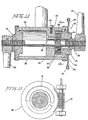
- Fig. 1 is a front view of a bicycle which includes a first preferred embodiment of a transmission apparatus, according to the present invention, for transmitting power from a rider of the bicycle to a ground engaging wheel of the bicycle;
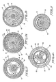
- Fig. 2 is a transverse, cross-sectional view of the first preferred embodiment of apparatus shown in Fig. 1, taken on the line 2-2;
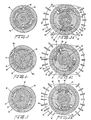
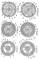
- Fig. 3 is a cross-sectional view of the apparatus shown in Fig. 2, taken on the line 3-3, at a beginning of a pedal drive cycle;
- Fig. 3a is a cross-sectional view of the apparatus shown in Fig. 2, taken on the line 3a-3a, also at the beginning of the pedal drive cycle;
- Fig. 4 is a cross-sectional view of the apparatus shown in Fig. 2, taken on the line 3-3, at a middle of the pedal drive cycle;
- Fig. 4a is a cross-sectional view of the apparatus shown in Fig. 2, taken on the line 3a-3a, also at the middle of the pedal drive cycle;
- Fig. 5 is a cross-sectional view of the apparatus shown in Fig. 2, taken on the line 3-3, at an end of the pedal drive cycle;
- Fig. 5a is a cross-sectional view of the apparatus shown in Fig. 2, taken on the line 3a-3a, also at the end of the pedal drive cycle;
- Fig. 6 is a front view of a bicycle which includes a second preferred embodiment of a transmission apparatus, according to the present invention, for transmitting power from a rider of the bicycle to a ground engaging wheel of the bicycle;
- Fig. 7 is a transverse, cross-sectional view of the second preferred embodiment of apparatus shown in Fig. 7, taken on the line 7-7;
- Fig. 8 is a cross-sectional view of the apparatus shown in Fig. 7, taken on the line 8-8, at a beginning of a pedal drive cycle;
- Fig. 8a is a cross-sectional view of the apparatus shown in Fig. 7, taken on the
line 8a-8a, at the beginning of the pedal drive cycle; - Fig. 8b is a cross-sectional view of the apparatus shown in Fig. 7, taken on the line 8b-8b, at the beginning of the pedal drive cycle;
- Fig. 9 is a cross-sectional view of the apparatus shown in Fig. 7, taken on the line 8-8, at a middle of the pedal drive cycle;
- Fig. 9a is a cross-sectional view of the apparatus shown in Fig. 7, taken on the
line 8a-8a, at the middle of the pedal drive cycle; - Fig. 9b is a cross-sectional view of the apparatus shown in Fig. 7, taken on the line 8b-8b, at the middle of the pedal drive cycle;
- Fig. 10 is a cross-sectional view of the apparatus shown in Fig. 7, taken on the line 8-8, at an end of the pedal drive cycle;
- Fig. 10a is a cross-sectional view of the apparatus shown in Fig. 7, taken on the
line 8a-8a, at the end of the pedal drive cycle; - Fig. 10b is a cross-sectional view of the apparatus shown in Fig. 7, taken on the line 8b-8b, at the end of the pedal drive cycle;
- Fig. 11 is a front view of a bicycle which includes a third preferred embodiment of a transmission apparatus, according to the present invention, for transmitting power from a rider of a bicycle to a ground engaging wheel of the bicycle;
- Fig. 12 is a transverse, cross-sectional view of the third preferred embodiment of apparatus shown in Fig. 11, taken on the line 12-12;
- Fig. 13 is a transverse, cross-sectional view of the third preferred embodiment of apparatus shown in Fig. 11, taken on the line 13-13;
- Fig. 14 is a cross-sectional view of the apparatus shown in Fig. 13, taken on the line 14-14, at a beginning of a pedal drive cycle;
- Fig. 15 is a cross-sectional view of the apparatus shown in Fig. 7, taken on the line 15-15;
- Fig. 16 is a cross-sectional view of the apparatus shown in Fig. 7, taken on the line 16-16;
- Fig. 17 is a qualitative plot of a torque transmitted to a ground engaging wheel of a bicycle incorporating the present invention, as a function of time during a pedal drive cycle, assuming a rider of the bicycle is delivering power at a constant pedal speed;
- Fig. 18 is a plot of an average torque transmitted to the ground engaging wheel of the bicycle incorporating the present invention, as a function of bicycle speed, assuming the rider of the bicycle is delivering power at a constant pedal speed;
- Fig. 19 is a plot of an average power transmitted to the ground engaging wheel of the bicycle incorporating the present invention, as a function of bicycle speed, assuming the rider of the bicycle is delivering power at a constant pedal speed; and
- Fig. 20 includes plots of an average power transmitted to a ground engaging wheel of a conventional, multi-geared bicycle, as a function of bicycle speed, for a plurality of different gear combinations.
- With reference primarily to Figs. 1 and 2, a first embodiment of apparatus for transmitting power from a rider of a bicycle to the bicycle, according to the present invention, includes a
bicycle frame 20, and aground engaging wheel 30. Theground engaging wheel 30 includes a hub 32 (shown in Fig. 2) and a plurality ofwheel spokes 34. - A
shaft 40 is rotatably connected to theframe 20 with both asprocket 42 and two cranks 44 rigidly connected to theshaft 40. Twopedals 46, each of which is connected to one of the cranks 44, may be selectively, drivingly engaged by the rider of the bicycle. - A motion reversing mechanism includes a figure-eight
chain 48. The figure-eightchain 48 links thesprocket 42 to asprocket 90 in a transmission mechanism 50 (shown in Fig. 2) housed in thehub 32 of theground engaging wheel 30. Two idler gears 49, which are spring loaded to take up chain slack, separate the figure-eightchain 48 at a crossover point. - By drivingly engaging the
pedals 46, a rider of the bicycle rotates theshaft 40, as well as thesprocket 42 rigidly mounted on theshaft 40, in a clockwise direction (as viewed in Fig. 1). The clockwise rotation of thesprocket 42 produces a clockwise rotation of the portion of the figure-eightchain 48 encircling thesprocket 42. However, the portion of the figure-eight chain encircling thesprocket 90 undergoes a counterclockwise rotation and urges thesprocket 90 to also rotate in the counterclockwise direction. Thus, the figure-eight chain achieves a motion reversal for the apparatus. That is, as thesprocket 42 rotates in the clockwise direction, thesprocket 90 is made to rotate in the counterclockwise direction. - With reference particularly to Fig. 2, the
transmission mechanism 50 includes anaxle 52 of thewheel 30, which axle is rigid with respect to theframe 20. Encircling theaxle 52 is acylindrical spring 54. A left-hand end of thespring 54 is connected to a left main bearing and spring mount 56, which bearing and spring mount 56 is rigidly mounted on a left-hand portion of theaxle 52. The bearing and spring mount 56 is prevented from undergoing a leftward longitudinal motion by a leftbearing tension nut 58 and aleft lock nut 59, which nuts encircle theaxle 52 and are arranged adjacent a left-hand end of the bearing and spring mount 56. - A
pawl mount 60 is rotatably mounted on a right hand portion of theaxle 52. A right-hand end of thespring 54 is connected to a left-hand portion of thepawl mount 60. Thepawl mount 60 includes twopawls 62, mounted in circular notches in the pawl mount (see also Fig. 3a). Thepawls 62 carried by thepawl mount 60 may engage the teeth of a ratchet wheel which is connected to an inner surface of thehub 32. - As described in more detail below, the
transmission mechanism 50 also includes an engaging mechanism mounted on theshaft 52 which enables a rider of the bicycle to periodically tension thespring 54. That is, the engaging mechanism enables the rider of the bicycle, in conjunction with the reversing mechanism described above, to rotate thepedals 46 in the clockwise direction (as viewed in Fig. 1) while periodically engaging and rotating thepawl mount 60 in the opposite direction, i.e. in the counterclockwise direction. Because the left-hand end of thespring 54 is connected to the bearing and spring mount 56 while the right-hand end of thespring 54 is connected to thepawl mount 60, the counterclockwise rotation of thepawl mount 60 by the engaging mechanism produces a tensioning of thespring 54. Thus, when thepawl mount 60 is periodically rotated in the counterclockwise direction by the engaging mechanism, thespring 54 is thereby periodically tensioned and energy is periodically stored in the spring. On the other hand, when thepawl mount 60 is periodically freed by the engaging mechanism, thespring 54, which has previously been tensioned, is then able to rotate thepawl mount 60 in the clockwise direction. As thepawl mount 60 is rotated in the clockwise direction the twopawls 62 carried by thepawl mount 60 engage the teeth of the ratchet wheel in the inner surface of thehub 32, thereby transferring the energy previously stored in thespring 54 to theground engaging wheel 30. - With reference again to Fig. 2, the engaging mechanism referred to above includes a
tubular member 64 which is connected to, and which extends to the right of, thepawl mount 60. The engaging mechanism also includes acam 70 which is rigidly mounted on theaxle 52, adjacent to and to the right of thepawl mount 60. Thecam 70 includes an outer surface having a lefthand portion, denoted by "Left", and a right-hand portion, denoted by "Right". Thepawls 62 are arranged on the pawl mount adjacent the left-hand portion of the outer surface of thecam 70. The axially extendingtubular member 64 of thepawl mount 60 encircles substantially the whole of the right- hand portion of the outer surface of thecam 70. - A
driver 80 is rotatably mounted on theaxle 52 adjacent to, and to the right of, thecam 70. Thedriver 80 includes atubular member 82 which projects axially to the left, and which encircles the right-hand portion of the outer surface of thecam 70. The leftward projectingtubular member 82 is positioned between the outer surface of thecam 70 and an inner surface of the rightwardly extendingtubular member 64. The leftward projectingtubular member 82 includes a cylindrical wall having apertures which containball bearings 84. Theball bearings 84 are in contact with the right- hand portion of the outer surface of thecam 70. - The
sprocket 90 is rigidly mounted on thedriver 80. One end of the figure-eight chain 48 (shown in Fig. 1), which chain encircles the sprocket 42 (shown in Fig. 1), also encircles thesprocket 90. The ratio of the diameter of thesprocket 90 anddriver 80, to the diameter of thesprocket 42, may, for example, be two-to-one. - A right
bearing tension nut 92, as well as aright lock nut 94, encircle theaxle 52 at a point adjacent to, and to the right of, thedriver 80. These nuts prevent thepawl mount 60, thecam 70, and thedriver 80 from undergoing a rightward longitudinal motion along theaxle 52. - The
axle 52 is rigidly connected to theframe 20 of the bicycle by conventional means (not shown). - With reference now to Fig. 3a, a left-hand portion of the outer surface of the
cam 70 includes two segments, 70a and 70b, each of which segments has a surface with a radius which varies from a first relatively large radius R1 to a second relatively small radius R2. Each segment of the left-hand portion of the outer surface of thecam 70 also has a shoulder which defines a juncture between the radius R1 and the radius R2. - The
pawl mount 60 includes twopawls 62, which pawls are pivotably connected to an outer surface of the pawl mount at two points which are diametrically opposed to one another. Each of thepawls 62 is urged to pivot into engagement with the teeth of the ratchet wheel connected to thehub 32 by a pawl-biasingspring 66. A first end of each of thesprings 66 is arranged within a cavity in a lower surface of each of thepawls 62. A second end of each of thesprings 66 projects through a slot in a cylindrical wall of thepawl mount 60, which cylindrical wall encircles the left-hand portion of thecam 70. The second end of each of thesprings 66 projecting through the cylindrical wall of thepawl mount 60 is mounted on aball 67. Each of theballs 67 rests on the surface of one of the two segments of the outer surface of the left- hand portion of thecam 70. - A
reset spring 68, in the form of a leaf spring, urges each of thepawls 62 to pivot out of engagement with the ratchet wheel in thehub 32. A first end of each of the reset springs 68 is arranged between a lower portion of each of thepawls 62 and an outer surface of thepawl mount 60, adjacent one of the points where thepawls 62 are pivotably connected to thepawl mount 60. This first end of eachreset spring 68 is connected to an outer surface of thepawl mount 60. A second end of each of the reset springs 68 is connected to a lower surface of each of thepawls 62. - With reference now to Fig. 3, the outer surface of the right-hand portion of the
cam 70 includes two concave segments, 70c and 70d, and two convex segments, 70e and 70f. Each concave segment is arranged between the two convex segments. - The
tubular member 82, which member projects axially leftward from the driver 80 (not shown in Fig. 3) to encircle the outer surface of the right-hand portion of thecam 70, carries four ball bearings 84 (denoted bynumerals tubular member 82. These apertures in which theball bearings 84 are located are arranged so that adjacent apertures are ninety degrees from each other. Theball bearings 84 in these apertures are in contact with the outer surface of the right-hand portion of thecam 70. - The
tubular member 64, which projects axially rightward from thepawl mount 60, encircles thetubular member 82. Thetubular member 64 includes an inner surface having two shoulders, 64a and 64b (see Fig. 4), which two shoulders are positioned one hundred and eighty degrees from each other. The two shoulders in the inner surface of thetubular member 64 may be engaged by theball bearings 84. - The first embodiment of apparatus described above operates cyclically as follows. With reference to Fig. 1, one of the
pedals 46 is initially assumed to be at about twenty degrees to the vertical. This pedal may be drivingly engaged by a rider of the bicycle and rotated in the clockwise direction through one hundred and eighty degrees. A complete one hundred and eighty degree rotation of one of thepedals 46 constitutes one complete pedal drive cycle. Of course, after onepedal 46 has been rotated through one hundred and eighty degrees, theother pedal 46 will have moved into a position at about twenty degrees to the vertical, and it too may then be drivingly engaged and rotated through one hundred and eighty degrees. - When one of the
pedals 46 is at about twenty degrees to the vertical, the position of this pedal, as well as the corresponding relative position of the components of the first embodiment of the present invention, constitutes a beginning of a pedal drive cycle. After thepedal 46 has been rotated through ninety degrees in the clockwise direction, the resulting position of thepedal 46 and of the components of the first embodiment constitutes a middle of the pedal drive cycle. After thepedal 46 has been rotated through yet another ninety degrees in the clockwise direction, i.e. after thepedal 46 has been rotated through a full one hundred and eighty degrees, the resulting position of thepedal 46 and of the components of the first embodiment constitutes an end of one pedal drive cycle and the beginning of another. - A clockwise rotation of one of the
pedals 46 produce an identical clockwise rotation of thesprocket 42. As thepedal 46 and thesprocket 42 rotate through one hundred and eighty degrees in the clockwise direction the figure-eight chain encircling thesprockets sprocket 90, and the driver 80 (not shown in Fig. 1) on which thesprocket 90 is mounted, to rotate through ninety degrees in the counterclockwise direction. This ninety degree rotation is due to the two-to-one ratio of the diameter of thesprocket 90 to the diameter of thesprocket 42. Because thedriver 80 undergoes only half the angular rotation that thepedal 46 and thesprocket 42 undergo, thedriver 80 arrives at the middle of. a pedal drive cycle after rotating forty-five degrees in the counterclockwise direction. Similarly, thedriver 80 arrives at the end of a pedal drive cycle after rotating an additional forty-five degrees in the counterclockwise direction, i.e. after rotating a total of ninety degrees in the counterclockwise direction. - With reference to Fig. 3, the relative positions of the components of the first preferred embodiment of apparatus, at a beginning of a pedal drive cycle, are such that two of the
ball bearings 84, denoted by the numerals "1" and "3", are each positioned on a convex segment of the outer surface of the right-hand portion of thecam 70. Each of these two ball bearings is in contact with one of the two shoulders in the inner surface of thetubular member 64, which tubular member is connected to the pawl mount 60 (not shown in Fig. 3). The two ball bearings denoted by the numerals "2" and "4" are each positioned on a concave segment of thecam 70. - With reference to Fig. 3a, the position of the
pawl mount 60, at the beginning of the pedal drive cycle, is such that each of theballs 67, each of which balls carries apawl biasing spring 66, is positioned on the left-hand portion of the outer surface of thecam 70, at a shoulder which defines the juncture between a segment having a radius R, and a segment having a radius R2. In this position, each of thepawls 62 is too far from the ratchet in the inner surface of thehub 32 for the pawl biasing springs 66 to urge thepawls 67 into engagement with the ratchet teeth. - With reference once again to Fig. 3, as the driver 80 (not shown in Fig. 3) begins to rotate in the counterclockwise direction at the beginning of the pedal drive cycle, the
tubular member 82 connected to thedriver 80 also begins to rotate in the counterclockwise direction. As thetubular member 82 begins to rotate in the counterclockwise direction two of the fourball bearings 84 carried by thetubular member 82, and denoted by the numerals "1" and "3", engage the two shoulders in the inner surface oftubular member 64. Because thetubular member 64 is connected to the pawl mount 60 (not shown in Fig. 3) thepawl mount 60 also rotates in the counterclockwise direction. The counterclockwise rotation of thepawl mount 60, to which pawl mount thespring 54 is connected, produces a tensioning of thecylindrical spring 54. - With reference to Fig. 4, after the driver 80 (not shown in Fig. 4), and the
tubular member 82 connected to thedriver 80, have rotated through forty-five degrees in the counterclockwise direction, which position defines a middle of the pedal drive cycle, the two bearings "1" and "3" engaging the two shoulders in the inner surface of thetubular member 64 fall into the two concave segments in the right-hand portion of the outer surface of thecam 70. When this occurs the pawl mount 60 (not shown in Fig. 4), which is connected to thetubular member 64,. and, accordingly, the spring 54 (also not shown in Fig. 4) become disengaged from thedriver 80. - With reference to Fig. 4a, as the
pawl mount 60 is rotated through forty-five degrees in the counterclockwise direction, theballs 67, on which the pawl-biasingsprings 66 are mounted, move in a counterclockwise direction over the left-hand portion of the outer surface of thecam 70. After moving in the counterclockwise direction through forty-five degrees each of theballs 67 reaches a segment of the left- hand portion of the outer surface of thecam 70 where the radius of the outer surface is R1. It is in this position, where each of thesprings 66 is relatively close to the ratchet wheel in thehub 32, that thesprings 66 can bias each of thepawls 62 to pivot into engagement with the ratchet wheel in thehub 32. In biasing thepawls 62 to pivot into engagement with the ratchet wheel in thehub 32 thesprings 66 overcome a radially inwardly directed biasing force exerted by the reset springs 68, which reset springs urge thepawls 62 to pivot out of engagement with the ratchet wheel. - With reference to Fig. 5, after the pawl mount 60 (not shown in Fig. 5), and the
tubular member 64 connected to thepawl mount 60, become disengaged from thedriver 80, the tensioned cylindrical spring 54 (not shown in Fig. 5) rotates thepawl mount 60 and thetubular member 64 through forty-five degrees in the ciockwise direction. While thepawl mount 60 and thetubular member 64 are rotating through forty-five degrees in the clockwise direction, thedriver 80 and thetubular member 82 connected to thedriver 80 continue to rotate in the counterclockwise direction through an additional forty-five degrees. After completing their respective rotations the resulting positions of thedriver 80, thetubular member 82, thepawl mount 60, and thetubular member 64, define an end of the pedal drive cycle. Because the pawls 62 (not shown in Fig. 5) carried by thepawl mount 60 have been brought into engagement with the ratchet wheel in the hub 32 (see Fig. 2), the clockwise rotation of thepawl mount 60 results in theground engaging wheel 30 also being rotated in the clockwise direction. Thus the energy stored in thecylindrical spring 54 is transmitted to theground engaging wheel 30. It is to be noted that substantially all of the energy stored in the cylindrical spring during the interval between the beginning and the end of a pedal drive cycle is delivered to theground engaging wheel 30 if the tensionedcylindrical spring 54 rotates thepawl mount 60 in the clockwise direction through a full forty-five degrees. - With reference to Fig. 5a, as the
pawl mount 60 rotates in the clockwise direction through forty-five degrees, each of theballs 67 simultaneously moves in the clockwise direction over the left hand portion of the outer surface of thecam 70. This clockwise motion of theballs 67 continues until each of theballs 67 reaches a segment of the lefthand portion of the outer surface of thecam 70 having a radius R2. It is in this position, where each of thesprings 66 is relatively far from the ratchet wheel in thehub 32, that thesprings 66 can no longer bias thepawls 62 to pivot into engagement with the ratchet wheel in thehub 32. Rather, the biasing force exerted by each of the reset springs 68 is now sufficient to pivot each of thepawls 62 out of engagement with the ratchet wheel in thehub 32. - With reference once again to Fig. 5, after the
pawl mount 60 and thetubular member 64 have completed their forty-five degree clockwise motions, the two ball bearings not previously in contact with the two shoulders in the inner surface of thetubular member 64, i.e. the two ball bearings denoted by the numerals "2" and "4", have meanwhile been rotated through an additional forty-five degrees in the counterclockwise direction by thetubular member 82 into position to engage these shoulders. Thus, this constitutes an end of one pedal drive cycle and the beginning of another. - In summary, the operation of the present invention is such that as a rider of the bicycle rotates one of the
pedals 46 through one hundred and eighty degrees in the clockwise direction, thedriver 80 is rotated through ninety degrees in the counterclockwise direction. As thedriver 80 rotates through an initial forty-five degrees in the counterclockwise direction, thedriver 80 actuates the engaging mechanism to engage and rotate thepawl mount 60 through forty-five degrees in the counterclockwise direction. As thepawl mount 60 rotates through forty-five degrees in the counterclockwise direction thecylindrical spring 54, one end of which is connected to thepawl mount 60, is tensioned. - After the
driver 80 has rotated through the initial forty-five degrees in the counterclockwise direction, the engaging mechanism becomes disengaged from thepawl mount 60. Thus, as thedriver 80 continues to rotate through another forty-five degrees in the counterclockwise direction, the tensionedcylindrical spring 54 rotates thepawl mount 60 through forty-five degrees in the clockwise direction. As thepawl mount 60 rotates in the clockwise direction through forty-five degrees, the twopawls 62 carried by thepawl mount 60 engage the ratchet wheel in thehub 32 of theground engaging wheel 30, rotating thewheel 30 in the clockwise direction, thereby propelling the bicycle in the forward direction. - An important feature of the transmission apparatus, and method of operation, described above is that after the
cylindrical spring 54 has relaxed and thepawls 62 have pivoted out of engagement with the ratchet wheel in thehub 32, the ground engaging wheel is freed from the transmission mechanism. Thus, in this condition the bicycle may be backed up. That is, the bicycle may be rolled in a direction opposite to an original forward direction, to permit the bicycle to be parked, for example. - With reference primarily to Fig. 6 and secondarily to Fig. 7, a second embodiment of apparatus for transmitting power from a rider of a bicycle to the bicycle, according to the present invention, includes a
bicycle frame 100, and aground engaging wheel 110. Theground engaging wheel 110 includes a hub 112 (shown in Fig. 7) and a plurality ofwheel spokes 114. - A
shaft 120 is rotatably connected to theframe 100, with both asprocket 122 and twocranks 124 rigidly connected to theshaft 120. Twopedals 126, each of which is connected to one of thecranks 124, may be selectively, drivingly engaged by the rider of the bicycle. - A
transmission chain 128 links thesprocket 122 to asprocket 162 in a transmission mechanism 130 (shown in Fig. 7) housed in thehub 112 of theground engaging wheel 110. In this second embodiment of the present invention, unlike the first embodiment, a clockwise rotation of thesprocket 122 also results in a clockwise rotation of thesprocket 162. A spring-loadedidler sprocket 129 maintains thetransmission chain 128 under tension, and prevents "flyback" when a compressed elastic member, mounted on an axle of theground engaging wheel 110, is periodically released. - With reference primarily to Fig. 7 and secondarily to Fig. 16, the
transmission mechanism 130 includes anaxle 132 of thewheel 110, which axle is rigid with respect to theframe 100. Encircling theaxle 132 is acylindrical spring 134. A left-hand end of thespring 134 is mounted in a semi-circular notch in a right- hand end of a bearing andspring mount 136, which bearing andspring mount 136 is mounted on a left-hand portion of theaxle 132. As shown in Fig. 16, a tip of the left-hand end of thespring 134 mounted in the semi-circular notch in the right-hand end of the bearing andspring mount 136 abuts against an end wall of the semi-circular notch. Thus when a right-hand end of thespring 134 is rotated in a counterclockwise direction (as viewed from the right in Fig. 7) the left-hand end of thespring 134 is held stationary. - With reference to Fig. 7, a spring
tension adjustment gear 138 is mounted on the bearing andmain spring mount 136. The bearing andmain spring mount 136 is prevented from undergoing a leftward longitudinal motion by a leftbearing tension nut 140, which nut encircles a threaded portion of theaxle 132 and is arranged adjacent a left-hand end of the bearing andspring mount 136. - With reference to Fig. 7 and Fig. 8b, a
cam 142, hereinafter referred to as the clutch cam, is rotatably mounted on a right-hand portion of theaxle 132. A righthand end of thespring 134 is mounted in a semi-circular notch in a left- hand portion of theclutch cam 142. As shown in Fig. 8b, a tip of the right-hand end of thespring 134 mounted in the semi-circular notch in the left-hand portion of theclutch cam 142 abuts against an end wall of this semi-circular notch. Thus, if theclutch cam 142 is rotated in a counterclockwise direction (as viewed from the right in Fig. 7), this end wall in the semi-circular notch is also rotated in the counterclockwise direction. Because the tip of the right-hand end of thespring 134 abuts against this end wall, it follows that the right-hand end of thespring 134 will also be rotated in the counterclockwise direction. - With reference primarily to Fig. 8b and secondarily to Fig. 7, an outer surface of the
clutch cam 142, which outer surface is substantially circular, includes four recesses, or notches, each of which recesses contains aroller 144. These recesses are substantially triangular in cross section, i.e., they each include a wide portion which gradually merges into a narrow portion. Each of the recesses also contains atension spring 145, one end of which spring is arranged in a cylindrical aperture in the wall of the recess, and another end of which is in contact with theroller 144. Therollers 144 are hereinafter referred to as the clutch cam rollers. The clutch cam rollers may frictionally engage an inner surface of thehub 112. - With reference once again to Fig. 8b and Fig. 7, two
pins clutch cam 142, project to the right from theclutch cam 142. Thepins clutch cam 142. - As described in more detail below, the
transmission mechanism 130 also includes a reversing mechanism and an engaging mechanism, both of which mechanisms are mounted on theaxle 132, and which mechanisms enable a rider of the bicycle to periodically tension thespring 134. That is, the reversing and engaging mechanisms enable the rider of the bicycle to rotate thepedals 126 in the clockwise direction (as viewed in Fig. 6) while periodically engaging and rotating theclutch cam 142 in the opposite direction, i.e. in the counterclockwise direction. Because the left-hand end of thespring 134 is mounted in the semi-circular notch in the bearing andspring mount 136, and the right- hand end of thespring 134 is mounted in the semi-circular notch in theclutch cam 142, as described above, the counterclockwise rotation of theclutch cam 142 by the reversing and engaging mechanisms produces a tensioning of thespring 134. Thus, when theclutch cam 142 is periodically rotated in the counterclockwise direction by the reversing and engaging mechanisms, thespring 134 is thereby periodically tensioned and energy is periodically stored in the spring. On the other hand, when theclutch cam 142 is periodically freed by the engaging mechanism, thespring 134, which has previously been tensioned, is then able to rotate theclutch cam 142 in the clockwise direction. As theclutch cam 142 is rotated in the clockwise direction the fourclutch cam rollers 144 carried by theclutch cam 142 frictionally engage the inner surface of thehub 112 thereby transferring the energy previously stored in thespring 134 to theground engaging wheel 110. - With reference to Fig. 7 and Fig. 8a, the engaging mechanism referred to above includes a
tubular member 146 projecting from theclutch cam 142. Thetubular member 146 projects to the right of theclutch cam 142. As shown more clearly in Fig. 8a, thetubular member 146 contains two longitudinal recesses, which recesses are approximately one hundred and eighty degrees apart from one another. Each of the recesses in thetubular member 146 contains aroller 147. Therollers 147 are hereinafter referred to as the driver cam rollers. - With reference again to Fig. 7 and Fig. 8a, a
cam 148 is rigidly mounted on theaxle 132, adjacent to and to the right of theclutch cam 142. Thecam 148 is hereinafter referred to as the driver cam. Thedriver cam 148 is rigidly mounted on theaxle 132 by means of a key 149. As shown in Fig. 8a, thedriver cam 148 includes an outer surface which is substantially circular. The outer surface of thedriver cam 148 includes two recesses, or notches, which recesses are approximately one hundred and eighty degrees apart from one another. The outer surface of thedriver cam 148 is encircled by thetubular member 146 projecting from theclutch cam 142. Thedriver cam rollers 147, carried by thetubular member 146, ride over the outer surface of thedriver cam 148. - With reference again to Fig. 7 and Fig. 8a, a right-hand end of the
driver cam 148 contains three equiangularly spaced longitudinal apertures. Each of these longitudinal apertures contains apin 150. Each of thepins 150 projects to the right of thedriver cam 148. Mounted on each of thepins 150 is aplanet gear 152. - With reference to Fig. 8a and Fig. 7, a left- hand end of the
driver cam 148 is provided with twocircular slots driver cam 148, and each of the slots subtends an angle of forty-five degrees. Thepin 143a projecting from the righthand end of theclutch cam 142 projects into an interior of theslot 151 a, while thepin 143b projects into an interior of theslot 151 b. An initial relative position of the clutch 142 and thedriver cam 148 is such that thepin 143a initially abuts against a right-hand end of theslot 151 a (as viewed in Fig. 8a), while thepin 143b initially abuts against a left-hand end of theslot 151b. Theslots pins clutch cam 142, to rotate through forty-five degrees in a counterclockwise direction (as viewed in Fig. 8b), relative to the initial position, but prevent thepins clutch cam 142 from undergoing a clockwise rotation relative to the initial position. - With reference to Fig. 7 and Fig. 8, the reversing mechanism referred to above includes a
nut 164, which nut encircles a right-hand, threaded portion of theaxle 132. Rotatably mounted on thenut 164 is asprocket mount 154. Atubular member 155, which tubular member is connected to thesprocket mount 154, projects to the left from thesprocket mount 154. Thetubular member 155 encircles theaxle 132 and is arranged between thedriver cam 148 and thesprocket mount 154. Mounted on thetubular member 155 is asun gear 156. As shown in Fig. 8, the teeth of thesun gear 156 may engage the teeth of the threeplanet gears 152, each of which planet gears is mounted on one of thepins 150 projecting from the driver cam 148 (not shown in Fig. 8). - With reference primarily to Figs. 7 and 8a, and secondarily to Fig. 8, a
ring gear 158 is rotatably mounted on thesprocket mount 154. As shown in Fig. 8, the teeth of the threeplanet gears 152 may engage the teeth of thering gear 158. As shown in Fig. 7, connected to thering gear 158, and projecting to the shaft from thering gear 158, is atubular member 160. Thistubular member 160 is hereinafter referred to as the cam driver. As shown in Fig. 8a, thecam driver 160, which is a component of the engaging mechanism, encircles thedriver cam 148 as well as thedriver cam rollers 147, which rollers roll over the outer surface of thedriver cam 148. An inner surface of thecam driver 160 includes four shoulders which are spaced ninety degrees apart from one other. The shoulders in the inner surface of thecam driver 160 may engage thedriver cam rollers 147. - With reference to Figs. 6, 7, and 8, and as described above, the
sprocket 162 is rigidly mounted on thesprocket mount 154. One end of thetransmission chain 128, which chain encircles thesprocket 122, also encircles thesprocket 162. Thesprocket mount 154 includes atubular member 155. As shown in Fig. 8 thesun gear 156 is mounted on thetubular member 155, and this sun gear has teeth which mesh with those of the planet gears 152. The planet gears 152 have teeth which mesh with those of thering gear 158. As is described below, a clockwise rotation of thesprocket 122 results in a counterclockwise rotation of thering gear 158. The dimensions of thesprockets gears sprocket 122 produces a ninety degree counterclockwise rotation of thering gear 158. - . With reference to Fig. 7, the
axle 132 is rigidly connected to theframe 100 of the bicycle by conventional means (not shown). - The second embodiment of apparatus described above operates cyclically as follows. With reference to Fig. 6, one of the
pedals 126 is initially assumed to be at about twenty degrees to the vertical. This pedal may be drivingly engaged by a rider of the bicycle and rotated in the clockwise direction through one hundred and eighty degrees. A complete one hundred and eighty degree rotation of one of thepedals 126 constitutes one complete pedal drive cycle. Of course, after onepedal 126 has been rotated through one hundred and eighty degrees, theother pedal 126 will have moved into a position at about twenty degrees to the vertical, and it too may then be drivingly engaged and rotated through one hundred and eighty degrees. - When one of the
pedals 126 is at about twenty degrees to the vertical, the position of this pedal, as well as the corresponding relative positions of the components of the second embodiment of apparatus of the present invention, constitutes a beginning of a pedal drive cycle. After thepedal 126 has rotated through ninety degrees in the clockwise direction, the resulting position of thepedal 126 and of the components of the second embodiment constitutes a middle of the pedal drive cycle. After thepedal 126 has been rotated through yet another ninety degrees in the clockwise direction, i.e. after thepedal 126 has been rotated through a full one hundred and eighty degrees, the resulting position of thepedal 126 and of the components of the second embodiment constitutes an end of one pedal drive cycle and the beginning of another. - A clockwise rotation of one of the
pedals 126 produces an identical clockwise rotation of thesprocket 122. As thepedal 126 and thesprocket 122 rotate through one hundred and eighty degrees in the clockwise direction, thetransmission chain 128, encirclingsprockets sprocket 162 and the sprocket mount 154 (not shown in Fig. 6), on which thesprocket 162 is mounted, to also rotate in the clockwise direction. - With reference to Figs. 8 and 9, the clockwise rotation of the sprocket mount 154 (not shown in Figs. 8 and 9) produces an identical rotation of the
tubular member 155, which tubular member is connected to thesprocket mount 154. Mounted on thetubular member 155 is thesun gear 156, which undergoes an identical clockwise motion. As thesun gear 156 rotates in the clockwise direction, the teeth of the sun gear mesh with the teeth of the planet gears 152, causing the planet gears to rotate in the opposite direction, i.e. in a counterclockwise direction. The teeth of the planet gears 152 in turn mesh with the teeth of thering gear 158 causing the ring gear, in turn, to rotate in the counterclockwise direction. As thering gear 158 rotates in the counterclockwise direction the cam driver 160 (not shown in Fig. 8 or Fig. 9), which is connected to thering gear 158, also rotates in the counterclockwise direction. Because there is an equivalent static gear ratio of two-to-one between thesprocket 162 and gears 156, 152, and 158, and thesprocket 122, it follows that a one hundred and eighty degree clockwise rotation of thesprocket 122 results in a ninety degree counterclockwise rotation of thering gear 158 and thecam driver 160. It is to be noted that because thering gear 158 andcam driver 160 undergo (in the counterclockwise direction) only half the (clockwise) angular rotation that thepedal 126 andsprocket 122 undergo, thering gear 158 andcam driver 160 arrive at the middle of a pedal drive cycle after rotating only forty-five degrees in the counterclockwise direction. Similarly, thering gear 158 andcam driver 160 arrive at the end of a pedal drive cycle after rotating a total of ninety degrees in the counterclockwise direction. - With reference to Fig. 8a and Fig. 8b, the relative positions of the components of the second preferred embodiment of apparatus, at a beginning of a pedal drive cycle, are shown by dots on each component, and are such that each of the
driver cam rollers 147 is positioned on a circular portion of the outer surface of thedriver cam 148. Each of thedriver cam rollers 147 is denoted either by a numeral "1" or a numeral "2". Thedriver cam rollers 147 are one hundred and eighty degrees apart from one another, and each is forty-five degrees away from a nearby slot, or recess, in the outer surface of thedriver cam 148. Two of the shoulders in the inner surface of thecam driver 160 are in contact with the twodriver cam rollers 147. Thepin 143a projecting into the interior of theslot 151 a, abuts against a right- hand end of theslot 151 a, while thepin 143b projecting into the interior of theslot 151 b, abuts against a lefthand end of theslot 151b. - With reference to Fig. 8b, at the beginning of the pedal drive cycle the four
clutch cam rollers 144 are positioned in their respective recesses in the outer surface of theclutch cam 142. Theclutch cam rollers 144, each of which is denoted by a numeraf "3", "4", "5", or "6", ride against their tension springs 145 and are relatively free from the inner surface of thehub 112. - With reference now to Figs. 9a and 9b, as the
cam driver 160 rotates in the counterclockwise direction, two of the four shoulders in the inner surface of thecam driver 160 engage thedriver cam rollers 147. Thedriver cam rollers 147 are thus urged to roll over the surface of thedriver cam 148 in a counterclockwise direction. The counterclockwise rotation of thedriver cam rollers 147 produces an identical counterclockwise rotation of thetubular member 146 which carries thedriver cam rollers 147. Because thetubular member 146 is connected to theclutch cam 142, the counterclockwise rotation of thetubular member 146 results in theclutch cam 142 also being rotated in the counterclockwise direction. The counterclockwise rotation of theclutch cam 142 results in thepins slots clutch cam 142 also results in a tensioning of thespring 134. - The counterclockwise rotation of the
driver cam rollers 147 proceeds until each of the rollers falls into a recess in the outer surface of thedriver cam 148. Upon falling into these recesses, thedriver cam rollers 147 become disengaged from thecam driver 160. The disengagement of thedriver cam rollers 147 from thecam driver 160 occurs after thedriver cam rollers 147 have rolled forty-five degrees in the counterclockwise direction, over the outer surface of thedriver cam 148. The moment of disengagement of thedriver cam rollers 147 from thecam driver 160 is the middle of a pedal drive cycle. - With reference to Figs. 10a, and 10b, after the
driver cam rollers 147 have become disengaged from thecam driver 160, the clutch cam 142 (shown in Fig. 10b) is rotated in the clockwise direction under the influence of thetensioned spring 134. The clockwise rotation of theclutch cam 142 results in thepins slots clutch cam 142 rotates in the clockwise direction, theclutch cam rollers 144, carried in recesses in the outer surface of theclutch cam 142, roll from the wider to the narrower portions of their recesses and frictionally engage the inner surface of thehub 112, causing the hub to rotate in the clockwise direction. - The clockwise rotation of the
clutch cam 142 results in a corresponding clockwise rotation of thetubular member 146, which tubular member is connected to theclutch cam 142. The clockwise rotation of thetubular member 146 in turn results in a corresponding clockwise rotation of thedriver cam rollers 147 over the outer surface of thedriver cam 148, which rollers are carried in longitudinal recesses in thetubular member 146. After thedriver cam rollers 147 have rotated forty-five degrees in the clockwise direction over the outer surface of thedriver cam 148, thedriver cam rollers 147 come into contact with the two shoulders in the inner surface of thecam driver 160 which had not previously engaged thedriver cam rollers 147. It is to be noted that thecam driver 160 continues to rotate in the counterclockwise direction throughout the entire pedal drive cycle. An end of the pedal drive cycle occurs at the instant that the two driver cam rollers come into contact with the two shoulders in the inner surface of thecam driver 160, which shoulders had not previously engaged thedriver cam rollers 147. This occurs after the cam driver has rotated a total of ninety degrees in the counterclockwise direction. - At the end of the pedal drive cycle, the
spring 134 has rotated theclutch cam 142 through forty-five degrees in a clockwise direction. During this clockwise rotation of theclutch cam 142 thespring 134 gives up all of the energy stored in the spring during the interval between the beginning of the pedal drive cycle and the middle of the pedal drive cycle. - In summary, and with reference to Figs. 6, 7, and 9, the operation of the second embodiment is such that a clockwise rotation of one of the
pedals 126 produces a clockwise rotation of thesprockets sprocket 162 rotates in the clockwise direction thesprocket mount 154, which carries thesprocket 162, also rotates in the clockwise direction. Thesun gear 156, which is mounted on thetubular member 155 connected to thesprocket mount 154, also rotates in the clockwise direction (as viewed in Fig. 9). But, as shown in Fig. 9, a clockwise rotation of thesun gear 156, whose teeth mesh with those of the planet gears 152, produces a counterclockwise rotation of the planet gears 152. The planet gears 152, which are rotated in the counterclockwise direction and which have teeth which mesh with those of thering gear 158, produce a counterclockwise rotation of thering gear 158. Thus, the reversing mechanism has transformed a clockwise rotational motion of thepedals 126 into a counterclockwise rotation of thering gear 158. - With reference to Figs. 7 and 9a, a counterclockwise rotation of the ring gear 158 (shown in Fig. 7) produces an identical counterclockwise rotation of the
cam driver 160, (as viewed in Fig. 9a), which cam driver is connected to thering gear 158. As shown in Fig. 9a, as thecam driver 160 rotates in the counterclockwise direction, two of the four internal shoulders in the inner surface of thecam driver 160 engage the twodriver cam rollers 147, which rollers roll over the surface of thedriver cam 148, and which rollers are carried by thetubular member 146. Thus, as therollers 147 are forced to roll in the counterclockwise direction over the surface of thedriver cam 148, thetubular member 146 is thereby also forced to rotate in the counterclockwise direction. Because thetubular member 146 is connected to the clutch cam 142 (not shown in Fig. 9a), and because a right-hand end of thespring 134 is mounted in a semi-circular notch in theclutch cam 142, theclutch cam 142 is rotated in the counterclockwise direction and thespring 134 is thereby tensioned. - When the
driver cam rollers 147 fall into the recesses in the outer surface of thedriver cam 148, thetubular member 146, as well as theclutch cam 142 to which thetubular member 146 is connected, is released from thecam driver 160. Thus, theclutch cam 142 may now be rotated in the clockwise direction under the influence of thetensioned spring 134 and theclutch cam rollers 144 can frictionally engage the inner surface of thehub 112. - With reference to Fig. 15, a rider of the bicycle may adjust the
transmission mechanism 130 to suit his own power speed characteristics by precompressing thespring 134. This precompression may be accomplished by rotating the main springtension adjustment gear 138 in a counterclockwise direction. The main springtension adjustment gear 138 is rigidly mounted on the bearing andmain spring mount 136, which spring mount includes a right-hand portion (as seen from Fig. 7) having a semi-circular notch. A left-hand portion of thespring 134 is embedded in this semi-circular notch. - The rotation of the main spring
tension adjustment gear 138 may be accomplished by turning aworm gear 139, whose teeth mesh with the teeth of the mainspringtension adjustment gear 138. Thespring 134 may be precompressed by rotating the main springtension adjustment gear 138 in a counterclockwise direction, while thespring 134 may be relaxed by rotating the main springtension adjustment gear 138 in a clockwise direction. The main springtension adjustment gear 138 may be rotated in a clockwise or counterclockwise direction by rotating theworm gear 139 in either a clockwise or counterclockwise direction. - It is to be noted that the
pins clutch cam 142 into the interiors of thecircular slots driver cam 148, permit theclutch cam 142 to rotate in a counterclockwise direction at the beginning of a pedal drive cycle, but prevent theclutch cam 142 from rotating in a clockwise direction at the beginning of a pedal drive cycle. This feature permits a precompression of thespring 134 to be maintained in the absence of any rotation of thepedals 126. That is, when thespring 134 is precompressed by rotating the main springtension adjustment gear 138, the resulting tension in thespring 134 urges theclutch cam 142 to rotate in the clockwise direction (as viewed in Fig. 8b). If theclutch cam 142 were allowed to rotate in the clockwise direction at the beginning of the pedal drive cycle thetensioned spring 134 could relax and thus no precompression of thespring 134 could be maintained. However, thepins slots clutch cam 142 from rotating in the clockwise direction at the beginning of a pedal drive cycle, thus permitting a precompression of thespring 134 to be maintained in the absence of any rotation of thepedals 126. - With reference to Figs. 11-13, a third embodiment of apparatus for transmitting power from a rider of a bicycle to the bicycle, according to the present invention, is similar to the second embodiment but differs in that a
motion reversing mechanism 230 is housed in a pedal hub 226 (shown in Fig. 13) near the front of the bicycle, while an engaging mechanism is housed in a hub 254 (shown in Fig. 12) of aground engaging wheel 210 near the rear of the bicycle. The third embodiment, like the second embodiment, includes abicycle frame 200, and aground engaging wheel 210. Theground engaging wheel 210 includes ahub 254 and a plurality ofwheel spokes 214. - With reference to Figs. 11 and 13, a
shaft 220 is rotatably connected to theframe 200.Cranks 222 are rigidly connected to threaded portions of theshaft 220, andpedals 224 are connected to thecranks 222. Thepedals 224 may be selectively, drivingly engaged by the rider of the bicycle. - With reference to Fig. 13, a
pedal hub 226 encircles theshaft 220 and is rigidly connected to theframe 200. Thepedal hub 226 houses themotion reversing mechanism 230, as well as afirst sprocket 248. - With reference to Figs. 11 and 12, a
transmission chain 250 links thefirst sprocket 248 to asecond sprocket 286 in amechanism 260 housed in thehub 254 of theground engaging wheel 210. Themechanism 260 includes an engaging mechanism for periodically compressing an elastic element, as well as a oneway clutch. A spring loadedidler gear 252 maintains thetransmission chain 250 under tension to prevent "flyback" when the elastic element is released after having been compressed. - With reference to Figs. 13 and 14, the
motion reversing mechanism 230 includes ahub mount 231 which encircles a lefthand, threaded portion of theshaft 220. Thehub mount 231 is mounted on theshaft 220 adjacent to, but to the right of, one of thecranks 222. Anannular member 232, which is to the right of, and spaced apart from, thehub mount 231, encircles theshaft 220 and is rigidly connected to thepedal hub 226 by ascrew 234. Theannular member 232 is hereinafter referred to as the planet gear mount. Theplanet gear mount 232 includes three equiangularly spaced longitudinal apertures. Each of the longitudinal apertures contains apin 236 which projects to the right from theplanet gear mount 232. Rotatably mounted on each of thepins 236 is aplanet gear 238. - A
sun gear 240 is rigidly mounted on theshaft 220 adjacent to, and to the right of, theplanet gear mount 232. The teeth of thesun gear 240 mesh with the teeth of the planet gears 238. - Rigidly mounted on a right-hand, threaded portion of the
shaft 220 is anut 242. Rotatably mounted on thenut 242 is afirst sprocket mount 244. Connected to thesprocket mount 244, and projecting to the left from thesprocket mount 244, is aring gear 246. The teeth of the planet gears 238 mesh with the teeth of thering gear 246. - With reference to Figs. 11 and 13, the
first sprocket 248 is rigidly mounted on thesprocket mount 244. Thetransmission chain 250 encircles thefirst sprocket 248 and links thefirst sprocket 248 to thesecond sprocket 286 in themechanism 260 housed in thehub 254 of theground engaging wheel 210. - With reference to Fig. 12, the
mechanism 260 includes anaxle 262 of thewheel 210, which axle is rigid with respect to theframe 200. Encircling theaxle 262 is acylindrical spring 264. Mounted on a left-hand portion of theaxle 262 is a bearing andmain spring mount 266. A right-hand portion of the bearing andspring mount 266 includes a semi-circular notch. As was the case with the second embodiment, a left-hand portion of thecylindrical spring 264 is embedded in this semicircular notch. Rigidly mounted on the bearing andmain spring mount 266 is a main springtension adjustment gear 268. Mounted on an extreme, left-hand, threaded portion of theaxle 262 is anut 270. Thenut 270 prevents the bearing andmain spring mount 266 from undergoing a leftward, longitudinal motion. - Rotatably mounted on a right-hand portion of the
axle 262 is acam 272. Thiscam 272 is hereinafter referred to as the clutch cam. Theclutch cam 272 includes a lefthand end which contains a semi-circular notch. As with the second embodiment, a righthand portion of thecylindrical spring 264 is mounted in this semi-circular notch. - The
clutch cam 272 includes a substantially cylindrical outer surface. This outer surface includes four equi-angularly spaced notches, or recesses. Each of these notches, or recesses, contains aroller 274. Therollers 274 are hereinafter referred to as the clutch cam rollers. Theclutch cam rollers 274 may frictionally engage an inner surface of thehub 254. - Projecting from a right-hand end of the
clutch cam 272, and connected to theclutch cam 272, is atubular member 276. Thetubular member 276 contains two longitudinal recesses which are one hundred and eighty degrees apart from one another. Each of the longitudinal recesses contains aroller 277. The tworollers 277 are hereinafter referred to as the driver cam rollers. - Rigidly mounted on the
axle 262, adjacent to and to the right of theclutch cam 272, is acam 278. Thecam 278 is hereinafter referred to as the driver cam. Thedriver cam 278 is rigidly connected to theaxle 262 by a key 279. Thedriver cam 278 includes an outer surface which is substantially cylindrical in shape. The outer surface of thedriver cam 278 includes two notches, or recesses, which are spaced apart from one another by one hundred and eighty degrees. Thedriver cam rollers 277, carried by thetubular member 276, are in contact with the outer surface of thedriver cam 278. - Rigidly mounted on a right-hand, threaded portion of the
axle 262 is anut 280. Rotatably mounted on thenut 280 is asecond sprocket mount 282. Connected to thesecond sprocket mount 282, and projecting to the left from thesecond sprocket mount 282, is atubular member 284. Thetubular member 284 is hereinafter referred to as the cam driver. Thecam driver 284 includes an inner surface having four equiangularly spaced shoulders. These four shoulders may engage thedriver cam rollers 277. - The
sprocket 286 is rigidly mounted on thesecond sprocket mount 282. Thesecond sprocket 286 is linked to thefirst sprocket 248 by thetransmission chain 250, which transmission chain encircles both sprockets. - The
axle 262 is rigidly connected to theframe 200 of the bicycle by conventional means (not shown). - The third embodiment of apparatus, like the second embodiment, also includes a mechanism for pretensioning the
spring 264. This mechanism includes a main springtension adjustment gear 268 mounted on the bearing andmain spring mount 266. A worm gear whose teeth mesh with those of the springtension adjustment gear 268, like the worm gear in Fig. 15, may be used to rotate thegear 268 in a clockwise or counterclockwise direction in order to relax or to pretension thespring 264. - The third embodiment, like the second embodiment, also includes two
pins 243a and 243b connected to a right-hand end of theclutch cam 272, and two circular slots in a left- hand end of thedriver cam 278. Each of the slots subtends an angle of forty-five degrees, and each of the pins projects into an interior of one of the slots. The slots permit the pins and theclutch cam 272 to rotate in a counterclockwise direction (as viewed from the right in Fig. 12) at the beginning of a pedal drive cycle, but prevent theclutch cam 272 from rotating in a clockwise direction at the beginning of a pedal drive cycle. Thus, a precompression of thespring 264 may be maintained in the absence of any rotation of thepedals 224. - With reference to Figs. 11-13, the third embodiment of apparatus described above operates in a fashion quite similar to that of the second embodiment. The one major difference in the operations of the second and third embodiments is that, with respect to the third embodiment, a clockwise motion of the
pedals 224 is transformed into a counterclockwise motion of thesprocket 248 by themotion reversing mechanism 230 housed in thepedal hub 226. Themechanism 260, housed in thehub 254 of theground engaging wheel 210, then produces a periodic tensioning of thecylindrical spring 264, and a periodic transfer of the energy periodically stored in thespring 264 to thehub 254. - It is to be noted that the dimensions of the
sprockets pedals 224 and theshaft 220 results in a ninety degree counterclockwise rotation of thesprocket 286. - The transmission apparatus of the present invention has a number of advantages. One such advantage is due to the use of a spring for storing energy because a spring can accept power from a rider of a bicycle at one speed while efficiently delivering power to a ground engaging wheel of the bicycle over a broad range of speeds. That is, as the rider rotates the pedals of the bicycle at a first speed, the cylindrical spring becomes linked to the pedals, and receives and stored energy from the rotating pedals, during a first portion of the pedal drive cycle. During a second portion of the pedal drive cycle the cylindrical spring becomes disengaged from the pedals and engages the ground engaging wheel of the bicycle through the free-wheeling clutch. It is during this second portion of the pedal drive cycle that the cylindrical spring relaxes and transfers its stored energy to the ground engaging wheel, which wheel may be rotating at a second speed that may be quite different from the first speed of the pedals. Another advantage of the present invention is that a rider of a bicycle is decoupled from a load on the bicycle. This is due to the fact that the rider is never directly linked to the ground engaging wheel of the bicycle, but is only indirectly linked through the energy-storing spring. Thus, as the terrain becomes steeper and the load on the bicycle correspondingly increases, the rider does not feel this increase in the load. The rider may continue to deliver whatever constant power he wishes to deliver to the bicycle, and the bicycle will continue to move in a forward direction. However, the speed of the bicycle will decrease as the terrain becomes steeper, and eventually the terrain may become so steep that the constant power delivered by the rider is no longer sufficient to propel the bicycle in the forward direction.
- Yet a further advantage of the present invention is that it is, in a sense, an automatic transmission. That is, with the present invention, a rider of a bicycle producing an average power need not shift through a plurality of gear combinations, as the speed of the bicycle changes, to transmit all of this average power to the bicycle, as is necessary with a conventional multi-geared bicycle. This is explained in more detail below.
- A qualitative plot of a torque delivered to a ground engaging wheel of a bicycle incorporating the present invention, as a function of time during a pedal drive cycle, when a rider of the bicycle is producing power at a constant pedal speed, is provided in Fig. 17. As shown in Fig. 17, if a rider of a bicycle produces power at a constant pedal speed, then the torque delivered to the ground engaging wheel of the bicycle by the elastic element of the present invention is zero during a first portion of the pedal drive cycle, increases to a maximum at the beginning of a second portion of the pedal drive cycle, and then decreases from this maximum to zero during the second portion of the pedal drive cycle. During the first portion of the pedal drive cycle the elastic element is being tensioned or cocked, and during the second portion of the pedal drive cycle the, elastic element relaxes. An average torque, T, delivered to the ground engaging wheel during a complete pedal drive cycle is that torque whose amplitude, multiplied by a length in time of a complete pedal drive cycle, is equal to an area under the torque versus time curve of the second portion of the pedal drive cycle.
- A qualitative plot of the average torque delivered to a ground engaging wheel of a bicycle incorporating the present invention, when a rider of the bicycle is producing power at a constant pedal speed, is provided in Fig. 18. As shown in Fig. 18, if the rider of the bicycle produces power at a constant pedal speed then the average torque, T, delivered by the present invention to the ground engaging wheel of a bicycle, decreases from a maximum, called the stall torque, is, when a speed of the bicycle, vb, is zero, toward zero as the speed of the bicycle increases.
- If the average power, P, delivered by the present invention to the ground engaging wheel of a bicycle ridden by a rider producing power at a constant pedal speed is defined to be the multiple of the average torque, T, and the bicycle speed, vbt i.e.

- A qualitative plot of a power delivered to a ground engaging wheel of a bicycle as a .function of bicycle speed, by each individual gear combination of a multi-geared conventional bicycle transmission, is provided in Fig. 20. As shown in this figure, the power produced by a rider of the bicycle, substantially all of which power is delivered by each gear combination of the bicycle transmission to the bicycle, varies sharply with bicycle speed. That is, each individual gear combination transmits to the bicycle substantially all of the maximum power delivered by a rider of the bicycle, only over a very narrow bicycle speed range. Thus, as the speed of the bicycle increases beyond the narrow speed range where a particular gear combination can transmit to the bicycle substantially all of the maximum power delivered by the rider, the rider must necessarily shift to another gear combination which can transmit to the bicycle substantially all of the maximum power delivered by the rider. In contrast, because the present invention transmits to the bicycle virtually all of a constant power delivered by the rider over a very wide bicycle speed range, and thereby avoids the need for shifting through a series of gear combinations, it may be termed an "automatic transmission".
- It is to be noted that the present invention acts like an ideal transmission only if there is sufficient time for the energy-storing spring to be cocked and completely uncocked. That is, there must be sufficient time for the spring to fully relax before being cocked again. Below the minimum bicycle speed, vbmin, the ground engaging wheel is rotating so slowly, i.e. the spring is being uncocked so slowly, that the spring will be cocked again before it has completely relaxed. Above the maximum bicycle speed, Vbma,(, an angular inertia of the spring prevents the spring from relaxing quickly enough to give up all of its stored energy to the very rapidly rotating ground engaging wheel of the bicycle. Depending on a number of factors Vbmln may be less than about five kilometers per hour, while vbmax may be in excess of about 500 kilometers per hour. Thus, the present invention may act like an ideal transmission for a speed ratio, i . e ., a ratio of vbmax to Vbmin' of about one hundred.
- Yet another advantage of the present invention is that the stall torque, as, delivered to a bicycle by the present invention is much higher than the stall torque delivered by a transmission of a conventional bicycle. In the conventional transmission, the stall torque is proportional to a multiple of three factors: the rider's weight; the ratio of the pedal radius to the radius of the ground engaging wheel; and the static gear ratio. That is,

- The stall torque is the largest torque which can be delivered to a bicycle. The magnitude of the stall torque is important because it determines, in effect, the steepest terrain which can be surmounted by the bicycle. That is, as the stall torque increases, the force that propels the bicycle at zero speed increases. As this force increases, the steepness of the terrain which may be surmounted by a bicycle increases. Thus, because the present invention delivers a much greater stall torque to a bicycle than a conventional transmission, the present invention enables a rider-propelled bicycle to rider over more steeply inclined terrain than is possible with a conventional bicycle.
- The large magnitude of the stall torque produced by the present invention is also advantageous because it implies that the acceleration which a bicycle will experience at low speeds is relatively high. The greater this acceleration the more quickly the bicycle will achieve a speed at which the present invention acts as an ideal transmission.
- It is to be noted that a conventional, multi-geared bicycle may be modified to include a two-to-one gear combination at low speeds in order to increase the deliverable stall torque. However, the advantage gained by such a modification is offset by the relatively poor power-bicycle speed characteristics of the different gear combinations of a conventional bicycle, including the two-to-one gear combination, as shown in Fig. 20. Thus, even with the inclusion of a low-speed two-to-one gear combination, the rider of a conventional bicycle would have to start shifting gears almost immediately in order to transmit effectively constant power to the bicycle.
Claims (20)
Applications Claiming Priority (2)
| Application Number | Priority Date | Filing Date | Title |
|---|---|---|---|
| US107917 | 1979-12-28 | ||
| US06/107,917 US4305599A (en) | 1979-12-28 | 1979-12-28 | Transmission for a wheeled vehicle |
Publications (3)
| Publication Number | Publication Date |
|---|---|
| EP0042421A1 EP0042421A1 (en) | 1981-12-30 |
| EP0042421A4 EP0042421A4 (en) | 1982-05-10 |
| EP0042421B1 true EP0042421B1 (en) | 1984-08-15 |
Family
ID=22319150
Family Applications (1)
| Application Number | Title | Priority Date | Filing Date |
|---|---|---|---|
| EP81900282A Expired EP0042421B1 (en) | 1979-12-28 | 1980-12-11 | A transmission for a velocipede |
Country Status (8)
| Country | Link |
|---|---|
| US (1) | US4305599A (en) |
| EP (1) | EP0042421B1 (en) |
| JP (1) | JPS56501846A (en) |
| AU (1) | AU540548B2 (en) |
| CA (1) | CA1131465A (en) |
| DE (1) | DE3068982D1 (en) |
| IT (1) | IT1134856B (en) |
| WO (1) | WO1981001822A1 (en) |
Families Citing this family (11)
| Publication number | Priority date | Publication date | Assignee | Title |
|---|---|---|---|---|
| US5292286A (en) * | 1992-05-14 | 1994-03-08 | Lan Jin Hua | Bicycle power train assembly |
| US6019385A (en) * | 1997-11-26 | 2000-02-01 | Kelley; Don | Energy storage device for personal vehicle |
| GB2346193A (en) * | 1999-02-01 | 2000-08-02 | John Richard Banks | Energy converter |
| CA2315499A1 (en) | 2000-08-09 | 2002-02-09 | Jason Dunkley | Regenerative braking mechanism |
| US6869384B2 (en) * | 2002-03-19 | 2005-03-22 | Su Chiang Shui | Exercising bicycle |
| US8240690B2 (en) * | 2007-04-13 | 2012-08-14 | Peter Lawrence Wills | Human energy transduction and storage system having a one-way clutch |
| KR100950995B1 (en) * | 2008-03-21 | 2010-04-02 | (주)엠비아이 | A transmission for motor |
| US20110230286A1 (en) * | 2010-03-17 | 2011-09-22 | Eli Cohen | Variable Drive Transmission |
| CN103935450B (en) * | 2014-04-28 | 2017-02-22 | 哈尔滨理工大学 | Power-assisting bicycle and power assisting method |
| US9879737B2 (en) | 2015-12-07 | 2018-01-30 | International Business Machines Corporation | Interlock braking system |
| US10787224B2 (en) * | 2018-06-27 | 2020-09-29 | Thomas M. Howe | Pedal powered vehicle |
Family Cites Families (15)
| Publication number | Priority date | Publication date | Assignee | Title |
|---|---|---|---|---|
| US3125889A (en) * | 1964-03-24 | Spring clutch and control means | ||
| FR341264A (en) * | 1904-02-19 | 1904-08-03 | Charles Leon Gaston Gineste La | Motor transmission of velocipeds allowing intermittent efforts followed by rest |
| FR360907A (en) * | 1905-03-18 | 1906-05-07 | Pierre Clavier | Propellant spring |
| FR352660A (en) * | 1905-03-23 | 1905-08-17 | Auguste Durand | Spring barrel driven bicycle |
| CH104005A (en) * | 1923-03-19 | 1924-03-17 | Werner Ernst | Spring drive bike. |
| US1572051A (en) * | 1925-06-13 | 1926-02-09 | Joseph F Sullivan | Motor vehicle |
| FR691860A (en) * | 1930-03-13 | 1930-10-28 | Control device for bicycles | |
| US2065034A (en) * | 1935-05-31 | 1936-12-22 | Structo Mfg Company | Riding toy |
| US2908356A (en) * | 1957-03-14 | 1959-10-13 | Earl D Daarud | Spring drive for bicycle |
| US2914956A (en) * | 1957-11-01 | 1959-12-01 | Ibm | Spring drive apparatus |
| FR1326568A (en) * | 1962-03-28 | 1963-05-10 | Mechanical relay for the rational use of muscle energy | |
| AT306536B (en) * | 1968-11-05 | 1973-04-10 | Shimano Industrial Co | Freewheel hub for bicycles with two-speed gears |
| US3760905A (en) * | 1971-02-01 | 1973-09-25 | G Dower | Human body power converter |
| US3768835A (en) * | 1971-10-15 | 1973-10-30 | Carolina Enterprises | Children{40 s riding toy having mechanical driving means |
| US3894615A (en) * | 1973-09-04 | 1975-07-15 | Lew Hyok S | Torque distributor |
-
1979
- 1979-12-28 US US06/107,917 patent/US4305599A/en not_active Expired - Lifetime
-
1980
- 1980-12-11 JP JP50050581A patent/JPS56501846A/ja active Pending
- 1980-12-11 DE DE8181900282T patent/DE3068982D1/en not_active Expired
- 1980-12-11 CA CA366,594A patent/CA1131465A/en not_active Expired
- 1980-12-11 AU AU67090/81A patent/AU540548B2/en not_active Ceased
- 1980-12-11 EP EP81900282A patent/EP0042421B1/en not_active Expired
- 1980-12-11 WO PCT/US1980/001653 patent/WO1981001822A1/en active IP Right Grant
- 1980-12-22 IT IT26872/80A patent/IT1134856B/en active
Also Published As
| Publication number | Publication date |
|---|---|
| CA1131465A (en) | 1982-09-14 |
| IT1134856B (en) | 1986-08-20 |
| AU540548B2 (en) | 1984-11-22 |
| EP0042421A4 (en) | 1982-05-10 |
| WO1981001822A1 (en) | 1981-07-09 |
| IT8026872A0 (en) | 1980-12-22 |
| DE3068982D1 (en) | 1984-09-20 |
| AU6709081A (en) | 1981-07-22 |
| US4305599A (en) | 1981-12-15 |
| JPS56501846A (en) | 1981-12-17 |
| EP0042421A1 (en) | 1981-12-30 |
Similar Documents
| Publication | Publication Date | Title |
|---|---|---|
| US4300784A (en) | Efficient, versatile oscillating pedal cycle | |
| US4108459A (en) | Spring powered bicycle | |
| EP0042421B1 (en) | A transmission for a velocipede | |
| US4437677A (en) | Hand and/or foot propelled vehicle | |
| US4630839A (en) | Propulsion mechanism for lever propelled bicycles | |
| US3954282A (en) | Variable speed reciprocating lever drive mechanism | |
| JPH022752B2 (en) | ||
| US5429379A (en) | Impulse drive mechanism and shock driver for a land vehicle | |
| US4272096A (en) | Powerful oscillating pedal bicycle | |
| US4766772A (en) | Hub mechanism for self-propelling type light vehicle | |
| EP0752950B1 (en) | Apparatus for propelling a manually-powered cycle | |
| EP2137056A1 (en) | A human energy transduction and storage system having a one-way clutch | |
| GB1581560A (en) | Drive systems for rider-propelled vehicles | |
| EP0425526A1 (en) | Torque responsive automatic shifting hub | |
| US3889974A (en) | Ergonomic drive for bicycles and other human powered machines | |
| US20050029037A1 (en) | Mechanical transmission | |
| JPH01132490A (en) | Hub for bicycle | |
| FR2733019A1 (en) | Vehicular mechanical transmission giving continuous torque variation, e.g. for diesel-electric locomotive | |
| CA1162405A (en) | Toy inertia motor | |
| EP3083383B1 (en) | A transmission for a human powered vehicle (hpv) and such vehicle | |
| EP4021790B1 (en) | Automatic cyclic transmission | |
| RU2009940C1 (en) | Bicycle wheel brake bush | |
| WO1994027861A1 (en) | Bicycle front fork suspension with front wheel drive mechanism | |
| WO2023237280A1 (en) | Scooter | |
| AU6052580A (en) | Efficient versatile oscillating pedal cycle |
Legal Events
| Date | Code | Title | Description |
|---|---|---|---|
| PUAI | Public reference made under article 153(3) epc to a published international application that has entered the european phase |
Free format text: ORIGINAL CODE: 0009012 |
|
| AK | Designated contracting states |
Designated state(s): DE FR GB |
|
| 17P | Request for examination filed |
Effective date: 19811028 |
|
| RBV | Designated contracting states (corrected) |
Designated state(s): DE FR GB LI LU NL SE |
|
| RBV | Designated contracting states (corrected) |
Designated state(s): DE FR GB |
|
| GRAA | (expected) grant |
Free format text: ORIGINAL CODE: 0009210 |
|
| AK | Designated contracting states |
Designated state(s): DE FR GB |
|
| REF | Corresponds to: |
Ref document number: 3068982 Country of ref document: DE Date of ref document: 19840920 |
|
| ET | Fr: translation filed | ||
| PGFP | Annual fee paid to national office [announced via postgrant information from national office to epo] |
Ref country code: FR Payment date: 19841031 Year of fee payment: 5 |
|
| PGFP | Annual fee paid to national office [announced via postgrant information from national office to epo] |
Ref country code: DE Payment date: 19850125 Year of fee payment: 5 |
|
| PLBE | No opposition filed within time limit |
Free format text: ORIGINAL CODE: 0009261 |
|
| STAA | Information on the status of an ep patent application or granted ep patent |
Free format text: STATUS: NO OPPOSITION FILED WITHIN TIME LIMIT |
|
| 26N | No opposition filed | ||
| GBPC | Gb: european patent ceased through non-payment of renewal fee | ||
| PG25 | Lapsed in a contracting state [announced via postgrant information from national office to epo] |
Ref country code: FR Free format text: LAPSE BECAUSE OF NON-PAYMENT OF DUE FEES Effective date: 19880831 |
|
| PG25 | Lapsed in a contracting state [announced via postgrant information from national office to epo] |
Ref country code: DE Effective date: 19880901 |
|
| REG | Reference to a national code |
Ref country code: FR Ref legal event code: ST |
|
| PG25 | Lapsed in a contracting state [announced via postgrant information from national office to epo] |
Ref country code: GB Free format text: LAPSE BECAUSE OF NON-PAYMENT OF DUE FEES Effective date: 19881118 |