EP0042284A1 - Entwicklungsapparat - Google Patents
Entwicklungsapparat Download PDFInfo
- Publication number
- EP0042284A1 EP0042284A1 EP81302671A EP81302671A EP0042284A1 EP 0042284 A1 EP0042284 A1 EP 0042284A1 EP 81302671 A EP81302671 A EP 81302671A EP 81302671 A EP81302671 A EP 81302671A EP 0042284 A1 EP0042284 A1 EP 0042284A1
- Authority
- EP
- European Patent Office
- Prior art keywords
- applicator roll
- blade
- contact
- wick
- tray
- Prior art date
- Legal status (The legal status is an assumption and is not a legal conclusion. Google has not performed a legal analysis and makes no representation as to the accuracy of the status listed.)
- Withdrawn
Links
- 239000007788 liquid Substances 0.000 claims abstract description 26
- 230000033001 locomotion Effects 0.000 claims description 22
- 239000000463 material Substances 0.000 claims description 12
- 230000009471 action Effects 0.000 claims description 11
- 230000007246 mechanism Effects 0.000 claims description 5
- 239000011435 rock Substances 0.000 claims 1
- 238000001035 drying Methods 0.000 abstract description 5
- 210000005069 ears Anatomy 0.000 description 3
- 230000000694 effects Effects 0.000 description 3
- 239000012530 fluid Substances 0.000 description 3
- 230000008901 benefit Effects 0.000 description 2
- 230000006835 compression Effects 0.000 description 2
- 238000007906 compression Methods 0.000 description 2
- 239000011148 porous material Substances 0.000 description 2
- 230000003213 activating effect Effects 0.000 description 1
- 230000004075 alteration Effects 0.000 description 1
- 230000003416 augmentation Effects 0.000 description 1
- 230000008859 change Effects 0.000 description 1
- 238000010276 construction Methods 0.000 description 1
- 238000000151 deposition Methods 0.000 description 1
- 125000000664 diazo group Chemical group [N-]=[N+]=[*] 0.000 description 1
- 239000004744 fabric Substances 0.000 description 1
- 238000012986 modification Methods 0.000 description 1
- 230000004048 modification Effects 0.000 description 1
- 230000002093 peripheral effect Effects 0.000 description 1
- 230000009467 reduction Effects 0.000 description 1
- 230000000284 resting effect Effects 0.000 description 1
- 238000005096 rolling process Methods 0.000 description 1
- 229920001059 synthetic polymer Polymers 0.000 description 1
Images


Classifications
-
- G—PHYSICS
- G03—PHOTOGRAPHY; CINEMATOGRAPHY; ANALOGOUS TECHNIQUES USING WAVES OTHER THAN OPTICAL WAVES; ELECTROGRAPHY; HOLOGRAPHY
- G03B—APPARATUS OR ARRANGEMENTS FOR TAKING PHOTOGRAPHS OR FOR PROJECTING OR VIEWING THEM; APPARATUS OR ARRANGEMENTS EMPLOYING ANALOGOUS TECHNIQUES USING WAVES OTHER THAN OPTICAL WAVES; ACCESSORIES THEREFOR
- G03B27/00—Photographic printing apparatus
- G03B27/02—Exposure apparatus for contact printing
- G03B27/14—Details
- G03B27/30—Details adapted to be combined with processing apparatus
-
- G—PHYSICS
- G03—PHOTOGRAPHY; CINEMATOGRAPHY; ANALOGOUS TECHNIQUES USING WAVES OTHER THAN OPTICAL WAVES; ELECTROGRAPHY; HOLOGRAPHY
- G03D—APPARATUS FOR PROCESSING EXPOSED PHOTOGRAPHIC MATERIALS; ACCESSORIES THEREFOR
- G03D5/00—Liquid processing apparatus in which no immersion is effected; Washing apparatus in which no immersion is effected
- G03D5/06—Applicator pads, rollers or strips
- G03D5/067—Rollers
Definitions
- This invention relates to the development of photo prints and is particularly applicable in the developing of diazo prints.
- the attitude of the metering blade with reference to the surface of the applicator roll determines the amount of developer solution which will be presented per unit area to the surface of the copy sheet. This attitude is accordingly rather critical.
- Prior machines have included apparatus which permits adjusting the attitude of the metering blade, but this was a relatively permanent setting which required stopping and servicing the machine in order to effect an adjustment, i.e., this was more in the nature of a service adjustment than one in which the operation could perform to meet the needs of the immediate situation.
- the width of the more highly developed band was approximately the width of the wick being used, and the spacing of the bands on the point was equal to the circumference of the applicator roll, it was determined that the source of the print nonuniformity was probably a feature of the equipment which involved the use of a wick to bring the developer liquid to the surface of the applicator roll. Further, since the problem did not arise except when the machine was turned off or in standby condition for an extended period, the change in conditon of the roll surface; as by drying out, was suspected as the probable cause.
- the present invention provides apparatus for developing copy material bearing a latent image comprising:
- the invention provides apparatus for developing copy material having a latent image comprising: an applicator roll for applying liquid developer to copy material to be developed; a metering blade for controlling the amount of liquid developer on the surface of the applicator roll; a rocking bar supporting said metering blade, said bar being supported for rocking movement by support members, one adjacent each end; means mounting said support members for shifting movement transversely of the axis of said applicator roll in a direction to increase or decrease the squeegee action applied to the surface of the applicator roll by said metering blade; and screw means associated with support members for accurately controlling the shifting movement thereof, and being so disposed as to be accessible for operator manipulation while the developing apparatus is in operation.
- the present invention may embody a device for withdrawing the wick from contact with the roll surface at the time the machine is turned off, substantially in concert with the withdrawal of the metering blade and the pressure blade which had previously been arranged for such withdrawal and restoration motion.
- the withdrawal motion of the wick may be arranged in a simple and convenient fashion which markedly simplifies the operation and sharply reduces the cost of embodying this feature in the machine.
- the wick which is of course preferably made of flexible fabric and which must extend across the full length of the applicator roll (which corresponds with the full width of the widest copy sheet), requires continuous support and is preferably mounted directly upon a wall of the tray which holds the supply of developer solution.
- the developer tray is mounted for slight bodily shifting movement (e.g. pivotal movement) which is sufficient to cause the wick to move between a position in contact with the applicator roll, and one in which it is out of contact.
- an arm on the tray makes frictional contact with one of the elements for supporting and moving the metering blade, and thus avoids any significant augmentation of the mechanical system for producing these motions.
- Embodiments of the present invention also include a means for effecting a very sensitive adjustment in the attitude of the metering blade against the metering surface roll surface, and one which can be availed of during machine operation, thus greatly assisting the operator in assessing accurately when the proper setting has been attained.
- a means for effecting a very sensitive adjustment in the attitude of the metering blade against the metering surface roll surface By rockably mounting the metering bar mechanism upon adjusting plates, one at each end, and providing a screw; control for swinging the adjusting plate at each end of the bar, the present invention makes it possible for the operator to readily effect a sensitive attitude adjustment while the machine is running, to view the results of the changed setting on a test point, and to make an immediate decision as to whether the operation is satisfactory or whether a slight additional refinement in adjustment of the metering blade attitude is required.
- FIG. 1 illustrates a copying machine 10 of the dizao type embodying an exposure portion 12 and a development portion 30.
- the exposure portion 12 is generally of a previously known configuration and includes feed belts 14 cooperating with a transparent exposure cylinder 16 which houses exposure lamps 18, and with guide rolls 20 to lead a copy sheet and a translucent original document counterclockwise around the cylinder 16 when the parts are caused to rotate by a conventional motor drive (not shown).
- a conventional motor drive not shown
- As the sheets are progressively exposed their leading edges emerge and are separated by the operator so that the original is caused to move leftward and to be suitably cared for as by manually rolling or passing into a collecting device.
- the leading edge of the exposed copy sheet is turned towards the right in Fig. 1 and guided into a chute 22 where it comes into contact with an outer run of the belt 14 and is conducted downwardly into the development portion 30 of the machine.
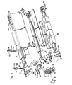
- the development portion 30 of the machine is characterized by a frame 31 in which is rotatably mounted an applicator roll 32 having a surface which is slightly resilient and microporous, and is capable of carrying devleoper fluid and depositing it upon the face of a copy sheet, in manner well known.
- the roll 32 is driven in a counterclockwise direction (as shown) by a suitable conventional power drive, e.g. the means which drives the rolls 20.
- a metering blade 34 supported on a metering bar 36 acts against the surface of the applicator roll 32 to determine the amount of liquid developer which the surface of the roll 32 will carry.
- a pressure blade 38 carried on a pressure bar 40.
- the blade 38 runs in contact with the applicator roll 32 and, when a copy sheet intervenes, serves to hold the copy sheet firmly in contact with the film of developer on the roll surface.
- Means which will be presently described is provided for rotating the bars 36 and 40 so as to move the blades 34 and 38 into and out of contact with the surface of the applicator roll 32.
- a tray 42 extending lengthwise of the machine.
- an upstanding wick 43 which extends to the bottom of the tray so as to be in contact with a bath 44 of developer in the tray 42 when it has been properly filled.
- the wick 43 extends upwardly to come into contact with the bottom of the applicator roll when the tray is in normal operating position as seen in Figs. 1 and 2.
- the tray 42 is pivotally mounted on the frame 31 of the development portion of the machine, the pivot being at that side of the tray remote from the wick 43.
- this pivotal mounting takes the form of two spring pressed pins 46 which may be manipulated by handles 48. The pins are located one at each end of the tray and may be withdrawn to permit release or replacement of the tray as well as permitting its rocking movements.
- the metering bar 36 is provided at one end with a slot 50 into which is fitted a key 52 for driving connection therewith, and bolted thereto is a bracket 54 whose tip carries a cam follower roller 56 on a pin 58 directed towards the interior of the machine.
- the pressure bar 40 is similarly equipped with a slot 60, key 62, an arm 64 which in this case is bolted directly to the face of the key and carries at its tip a cam follower roller 66 mounted upon a pin 67 which, in this case projects away from the interior of the machine.
- the cam follower rollers are designed to cooperate with face cam grooves formed on the opposite faces of a cam member 68.
- a groove 70 receiving the roller 56
- a cam groove 72 receiving the roller 66.
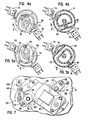
- the cam is shown in detail in Figs. 4a, 4b, 5a and 5b, in which it can be seen that the cam also includes a peripheral notch 74 for coacting with electrical control switches 76 and 78 for a purpose which will presently appear.
- the cam is connected to and driven by the shaft of a blade positioning motor 80, Figs. 6 and 7.
- cam positioning motor 80 The operation of the cam positioning motor 80 is as follows, the parts being assumed to be initially in the position of Figs. 5a and 5b with the machine off and the blades 34 and 38 out of contact with the applicator roll 32 as seen in Fig. 3.
- a print switch (not shown) is manually turned on, and this acts to start rotation of the applicator roll 32, and, in combination with the now closed switch 76, to energize the motor 80 causing the cam 68 to start turning in the direction of arrow A.
- This action first causes follower 56 to move the metering blade 34 into contact with the applicator roll 32, and then to cause the follower 66 to move the pressure blade 38 into contact, and finally the switch 76 opens when it encounters the notch 74, thereby deenergizing the positioning motor 80 to stop the cam and to transfer control, as by a relay, to now closed switch 78 in combination with an "off" actuation of the print switch.
- the -motor 80 and cam 68 remain stationary as long as the machine is in use for copying, and occupy the position of Figs. 4a, 4b during this running period, the blades 34 and 38 being in the position shown in Fig. 2.
- the previously described pivotal mounting of the tray 42 is for the purpose of moving the wick 43 into and out of contact with the applicator roll 32, and represents the presently preferred way of moving the wick since it avoids the problem of having to take the liquid level in the tray into account as would be the case if the wick were moved independently of the tray.
- each end of the tray is provided with a bracket.
- Each of the brackets is provided with a wear-resistant friction pad 84, preferably of a suitable synthetic polymer, so disposed as to face the metering bar 36 and to interfere slightly with the same as it is rocked.
- the noncircular shape of the bar 36 is an advantage in this regard in that the corner edge 86 of the bar serves as a particularly effective driving element for making contact with the friction pad 84.
- the bracket 82 can be adjusted horizontally and clamped in place by a bolt 88.
- the tray end plates are each provided with projecting ears 90 and 92 which coact with a tie bar 94 on the machine to determine the limits of up and down movement of the tray.
- the arrangement for securing a correct attitude setting of the metering blade 34 against the applicator roll to insure correct devleopment includes the key 52 and the bracket 54 seen in Fig. 6. These are relatively angularly shiftable about the shaft axis and can be clamped in various angular relationships by a screw 95 threaded into an opening 96 in the key 52 and passing through an arcuate slot 98.
- This is a formerly known arrangement which allows the metering bar 36 to be set at various angles with respect to a given position of follower roller 56 in its cam groove 70. It provides an effective way of adjusting blade attitude, but is a rather difficult adjustment for an operator to perform, and cannot, in a practical sense, be made while the machine is developing a print.
- the metering bar instead of having a mounting which is substantially fixed with respect to the side plates, is mounted near each of its ends for rotation in a swinging support plate 100.
- a swinging support plate 100 One of the plates can be seen in Fig. 1 and Fig. 7 and both appear in Fig. 6.
- Each plate has a pivotal mounting on the frame 3 as indiacted at 102.
- To the free end of each support plate 100 is rockably attached to a block 104 which has a threaded opening which threadedly receives the end of an adjusting screw 106.
- the screw is loosely supported in an opening in a guide bracket 108 attached to the frame 31, and a compression spring 110 surrounds the screw 106 and is trapped between the block 104 and the bracket 108.
- the compression spring 110 serves to maintain the head of the adjusting screw against the guide bracket 108 and to prevent vibration from changing the adjustment.
- the screws 106 can be tightened (rotated clockwise) by an equal amount to cause the blade 34 to attack the roll 32 in a more nearly tangential fashion which allows a slightly increased deposit of developer to remian on the roll surface, resulting in increased developing action.
- the screws 106 are so positioned that the operator has ready access to the screw heads from the top of the machine while the machine is operating so that the results of a changed blade setting are directly and immediately observable.
Landscapes
- Physics & Mathematics (AREA)
- General Physics & Mathematics (AREA)
- Coating Apparatus (AREA)
- Photographic Processing Devices Using Wet Methods (AREA)
Applications Claiming Priority (2)
| Application Number | Priority Date | Filing Date | Title |
|---|---|---|---|
| US159258 | 1980-06-13 | ||
| US06/159,258 US4299472A (en) | 1980-06-13 | 1980-06-13 | Developer apparatus |
Publications (1)
| Publication Number | Publication Date |
|---|---|
| EP0042284A1 true EP0042284A1 (de) | 1981-12-23 |
Family
ID=22571765
Family Applications (1)
| Application Number | Title | Priority Date | Filing Date |
|---|---|---|---|
| EP81302671A Withdrawn EP0042284A1 (de) | 1980-06-13 | 1981-06-15 | Entwicklungsapparat |
Country Status (5)
| Country | Link |
|---|---|
| US (1) | US4299472A (de) |
| EP (1) | EP0042284A1 (de) |
| JP (1) | JPS5727259A (de) |
| BR (1) | BR8103724A (de) |
| CA (1) | CA1165998A (de) |
Families Citing this family (3)
| Publication number | Priority date | Publication date | Assignee | Title |
|---|---|---|---|---|
| DE3311890A1 (de) * | 1982-03-31 | 1983-10-06 | Ricoh Kk | Entwicklungeinrichtung |
| EP0828189B1 (de) * | 1996-08-14 | 2004-11-10 | Mitsubishi Paper Mills, Ltd. | Gerät zur Behandlung fotoempfindlichen Materials |
| US7731347B2 (en) * | 2005-12-23 | 2010-06-08 | Xerox Corporation | Drum maintenance system for an imaging device and method and system for maintaining an imaging device |
Citations (5)
| Publication number | Priority date | Publication date | Assignee | Title |
|---|---|---|---|---|
| US3748996A (en) * | 1972-04-03 | 1973-07-31 | Ricoh Kk | Wet developing device for diazo type copying machines |
| GB1335850A (en) * | 1969-11-14 | 1973-10-31 | Xerox Corp | Cleaning apparatus |
| US3943540A (en) * | 1974-04-24 | 1976-03-09 | Addressograph-Multigraph Corporation | Photographic developing apparatus |
| US3969742A (en) * | 1974-04-24 | 1976-07-13 | Addressograph Multigraph Corporation | Automatic engagement and metering adjustment controls for metering blade device |
| US4158495A (en) * | 1978-06-16 | 1979-06-19 | Am International, Inc. | Developer apparatus for diazotype copy materials |
Family Cites Families (10)
| Publication number | Priority date | Publication date | Assignee | Title |
|---|---|---|---|---|
| US2036972A (en) * | 1935-03-04 | 1936-04-07 | Standard Mailing Machines Comp | Apparatus for duplicating printed matter |
| US2534765A (en) * | 1948-05-06 | 1950-12-19 | Ditto Inc | Liquid applicator for duplicating machines |
| US2698453A (en) * | 1952-09-11 | 1955-01-04 | Blaw Knox Co | Holder for interchangeably supporting knives against the periphery of revolving drums |
| US3262381A (en) * | 1963-09-30 | 1966-07-26 | Deluxe Lab Inc | Method and apparatus for improving upon the reproduction of images recorded on a photographic film |
| US3309992A (en) * | 1964-03-09 | 1967-03-21 | John C Motter Printing Press C | Blade adjsuting and clamping method and apparatus |
| US3498203A (en) * | 1967-06-07 | 1970-03-03 | Polaroid Corp | Capillary applicator |
| US3704662A (en) * | 1970-04-27 | 1972-12-05 | Addressograph Multigraph | Liquid developing apparatus |
| US3704661A (en) * | 1970-04-27 | 1972-12-05 | Dennis E Toby | Liquid developing apparatus |
| US3702096A (en) * | 1971-07-08 | 1972-11-07 | Addressograph Multigraph | Copy apparatus |
| JPS5521337B2 (de) * | 1972-12-12 | 1980-06-09 |
-
1980
- 1980-06-13 US US06/159,258 patent/US4299472A/en not_active Expired - Lifetime
-
1981
- 1981-05-27 CA CA000378399A patent/CA1165998A/en not_active Expired
- 1981-06-11 BR BR8103724A patent/BR8103724A/pt unknown
- 1981-06-12 JP JP9070381A patent/JPS5727259A/ja active Pending
- 1981-06-15 EP EP81302671A patent/EP0042284A1/de not_active Withdrawn
Patent Citations (5)
| Publication number | Priority date | Publication date | Assignee | Title |
|---|---|---|---|---|
| GB1335850A (en) * | 1969-11-14 | 1973-10-31 | Xerox Corp | Cleaning apparatus |
| US3748996A (en) * | 1972-04-03 | 1973-07-31 | Ricoh Kk | Wet developing device for diazo type copying machines |
| US3943540A (en) * | 1974-04-24 | 1976-03-09 | Addressograph-Multigraph Corporation | Photographic developing apparatus |
| US3969742A (en) * | 1974-04-24 | 1976-07-13 | Addressograph Multigraph Corporation | Automatic engagement and metering adjustment controls for metering blade device |
| US4158495A (en) * | 1978-06-16 | 1979-06-19 | Am International, Inc. | Developer apparatus for diazotype copy materials |
Also Published As
| Publication number | Publication date |
|---|---|
| CA1165998A (en) | 1984-04-24 |
| US4299472A (en) | 1981-11-10 |
| JPS5727259A (en) | 1982-02-13 |
| BR8103724A (pt) | 1982-03-02 |
Similar Documents
| Publication | Publication Date | Title |
|---|---|---|
| US4008957A (en) | Reproduction machine control | |
| CA1055560A (en) | Construction of electrophotographic copying machines with a cleaning unit for photosensitive surface | |
| US3716221A (en) | Fusing device | |
| EP0729833B1 (de) | Farbwerk für Druckmaschinen | |
| US4299472A (en) | Developer apparatus | |
| PL145098B1 (en) | Machine for printing characters on a cinematograph film | |
| US3820892A (en) | Double reel apparatus for electrostatically producing copies and matrices | |
| US3408934A (en) | Blanket cleaning attachment for offset presses | |
| JPS6216902B2 (de) | ||
| US3150588A (en) | Cylinder mounting, adjusting and interrupting means for offset printing and like machines | |
| US4566784A (en) | Photographic roller copying apparatus with a device for threading a new paper tape | |
| US4963896A (en) | Recording media transporting device with arcshaped path | |
| US3969742A (en) | Automatic engagement and metering adjustment controls for metering blade device | |
| US5066973A (en) | Image forming apparatus using an elongated web-like recording medium | |
| US4141314A (en) | Photocopying systems | |
| JPH06308842A (ja) | 画像形成装置 | |
| US3472590A (en) | Photocopy apparatus | |
| US6844944B2 (en) | Photographic paper exposing method and an optical digital printer employing this method | |
| US3616741A (en) | Apparatus for use in diffusion transfer copying | |
| JP3297522B2 (ja) | シート給送装置及び画像形成装置 | |
| CA1134672A (en) | Stencil duplicator | |
| US4095885A (en) | Polarity switch circuit for copying apparatus | |
| US3996853A (en) | Stencil loading device | |
| US2933031A (en) | Automatic light changer for motion picture printers | |
| US3615133A (en) | Photocopy apparatus |
Legal Events
| Date | Code | Title | Description |
|---|---|---|---|
| PUAI | Public reference made under article 153(3) epc to a published international application that has entered the european phase |
Free format text: ORIGINAL CODE: 0009012 |
|
| AK | Designated contracting states |
Designated state(s): DE FR GB NL |
|
| 17P | Request for examination filed |
Effective date: 19820609 |
|
| STAA | Information on the status of an ep patent application or granted ep patent |
Free format text: STATUS: THE APPLICATION IS DEEMED TO BE WITHDRAWN |
|
| 18D | Application deemed to be withdrawn |
Effective date: 19831228 |
|
| RIN1 | Information on inventor provided before grant (corrected) |
Inventor name: HUDSON, WALTER A. Inventor name: SEELENBINDER, TERRY G. |