EP0042047B1 - Method of, and apparatus for, constructing a laminated rotor - Google Patents
Method of, and apparatus for, constructing a laminated rotor Download PDFInfo
- Publication number
- EP0042047B1 EP0042047B1 EP81102648A EP81102648A EP0042047B1 EP 0042047 B1 EP0042047 B1 EP 0042047B1 EP 81102648 A EP81102648 A EP 81102648A EP 81102648 A EP81102648 A EP 81102648A EP 0042047 B1 EP0042047 B1 EP 0042047B1
- Authority
- EP
- European Patent Office
- Prior art keywords
- lamina
- shaft
- station
- rotor
- stock
- Prior art date
- Legal status (The legal status is an assumption and is not a legal conclusion. Google has not performed a legal analysis and makes no representation as to the accuracy of the status listed.)
- Expired
Links
Images

Classifications
-
- B—PERFORMING OPERATIONS; TRANSPORTING
- B21—MECHANICAL METAL-WORKING WITHOUT ESSENTIALLY REMOVING MATERIAL; PUNCHING METAL
- B21D—WORKING OR PROCESSING OF SHEET METAL OR METAL TUBES, RODS OR PROFILES WITHOUT ESSENTIALLY REMOVING MATERIAL; PUNCHING METAL
- B21D28/00—Shaping by press-cutting; Perforating
- B21D28/02—Punching blanks or articles with or without obtaining scrap; Notching
- B21D28/10—Incompletely punching in such a manner that the parts are still coherent with the work
-
- H—ELECTRICITY
- H02—GENERATION; CONVERSION OR DISTRIBUTION OF ELECTRIC POWER
- H02K—DYNAMO-ELECTRIC MACHINES
- H02K15/00—Processes or apparatus specially adapted for manufacturing, assembling, maintaining or repairing of dynamo-electric machines
- H02K15/02—Processes or apparatus specially adapted for manufacturing, assembling, maintaining or repairing of dynamo-electric machines of stator or rotor bodies
- H02K15/028—Fastening stator or rotor bodies to casings, supports, shafts or hubs
Definitions
- This invention relates to the manufacture of laminated dynamoelectric motor structures.
- Each of the above patents disclose die apparatus having a plurality of stations for seriatim operation up to the removal of the completed stacks.
- One of the drawbacks of such system is that the whole process is slowed down by a number of operations that have to be done after the completion of a stack, before the next laminae can be processed for starting a new stack. Time and cost efficiency are therefore reduced.
- U.S. patent 2,975, 312 relates to correspondingly formed projections and openings in adjacent laminae for interlocking a stack of laminae without a separate fastening element.
- the present invention provides a method of, and an apparatus for, constructing a laminated rotor, as defined in claims 1 and 4 and which provide a progressive punch with a plurality of stations for forming lamina of desired configuration from sheet stock. Each lamina is then returned to the sheet stock for travel therewith.
- a rotatable carousel carrying a plurality of stations at which laminations may be stacked.
- the last station in the preferred embodiment is a removal station at which the operator can remove the just formed stack and insert a shaft for receiving another stack.
- another stack is being processed resulting in a time and cost efficient method of forming laminated rotor structures.
- a stack structure 10 comprising a plurality ot ina) V )Oua) laminae 12 which together make up a rotor for a dynamoelectric machine, in particular a high speed stepper motor.
- Each lamina 12 is illustrated having alternatingly placed two holes 14 and two correspondingly shaped projections 16. While four have been shown it is obvious to those skilled in the art that other spacings may be chosen.
- progressive die 20 includes a plurality of forming stations (not shown) for forming individual lamina 12 from sheet stock 12.
- Sheet stock 22 is moved progressively through progressive die 20 in a conventional manner by means not shown in the direction of arrow 24.
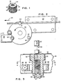
- Carousel 30 is provided with three work stations 31, 34, and 36. At each of stations 31, 34, and 36, the same operations may occur as carousel 30 rotates past three operation stations, 32, 38, and 40, positioned at evenly spaced locations about its periphery.
- Adjacent carousel work station 31 though not shown in Fig. 2 is apparatus located as indicated generally by 32 for blanking the individual lamina formed in sheet stock 22 and forming stack structure 10. This blanking' stacking apparatus will be described in detail with respect to Fig. 3.
- Projections 16 and holes 14 cooperate to maintain adjacent laminae in an interlocked manner. Each lamina is connected to its neighbor.
- stack 10 is a relatively stabilized structure and a clipping operation may be unnecessary.
- Indicated generally at 40 is the location of is a stack removal station. It is here that an operator must intervene to remove a completed stack and prepare the machine for its next cycle by inserting a stack receiving shaft.
- Fig. 3 illustrates apparatus 32 for dislodging an individual lamina 12 from sheet stock 22 and adding it to a developing stack 10 around operator removable stack receiving shaft 50.
- Blanking punch 52 is provided to press an individual lamina 12 from sheet stock 22 onto shaft 50.
- Shaft 50 is removably attached in member 54 which is rotatably mounted in a plate member.
- One way clutch 58 and gear 60 are provided to allow precisely indexed rotation of member 54 and, therefore, a stack 10 of laminae 12 being accumulated on shaft 50.
- Knockout rods 62 and 64 are provided to aid in the removal of stack structure 10 when it has reached its desired height.
- FIG. 3 Also seen in Fig. 3 is a side view of spring 66 biased rod 68, for rotating member 54.
- Rod 68 which can be seen more clearly in Fig. 4, is provided with teeth 70 for engaging gear 60.
- Shot pin 69 is provided to lock carousel 30 in position after each index.
- Gear 60 is driven by bar 68 through one way clutch 58 approximately 90°. Motion is imparted to bar 68 by means of dog leg cam 74 co-acting with camming surface 72.
- Fig. 5 shows cam 74 and rod 68 in cross- section.
- Cam 74 may be moved in the directions indicated by arrows 75 in any chosen manner to impart motion in directions indicated by arrows 77 to bar 68. It is to be appreciated that this design of bar 68 and gear 60 is for illustration purposes only and that other techniques for accurately indexing may be employed.
- a strip 22 advances through progressive die 20 in the direction indicated by arrow 24 until a blanked, and subsequently returned, lamina 12 is positioned over shaft 50 of a carousel mounted work station as shown in Fig. 3.
- Punch 52 is actuated to press lamina 12 down onto developing rotor stack structure 10.
- Punch 52 has teeth 52 provided about its lower periphery. These teeth correspond in number and spacing to those desired for the resulting rotor, as is of course to be understood by those skilled in the art.
- carousel 30 rotates counterclockwise, as indicated in Fig. 1. It is, of course, within the skill of the art to employ any of numerous techniques to detect the achievement of a predetermined height. For example, a means for counting the laminae forced on the shaft may be used. It would be a matter of choice, in the alternative to position a sensor to detect height.
- Stack structure 10 formed at station 32 is brought to the location adjacent the clip applying means formerly occupied by work station 34. There, press 38 is actuated to attach a one way clip on shaft 50.
Landscapes
- Engineering & Computer Science (AREA)
- Manufacturing & Machinery (AREA)
- Power Engineering (AREA)
- Mechanical Engineering (AREA)
- Manufacture Of Motors, Generators (AREA)
- Laminated Bodies (AREA)
Applications Claiming Priority (2)
| Application Number | Priority Date | Filing Date | Title |
|---|---|---|---|
| US15976080A | 1980-06-16 | 1980-06-16 | |
| US159760 | 1980-06-16 |
Publications (2)
| Publication Number | Publication Date |
|---|---|
| EP0042047A1 EP0042047A1 (en) | 1981-12-23 |
| EP0042047B1 true EP0042047B1 (en) | 1984-04-18 |
Family
ID=22573904
Family Applications (1)
| Application Number | Title | Priority Date | Filing Date |
|---|---|---|---|
| EP81102648A Expired EP0042047B1 (en) | 1980-06-16 | 1981-04-08 | Method of, and apparatus for, constructing a laminated rotor |
Country Status (3)
| Country | Link |
|---|---|
| EP (1) | EP0042047B1 (show.php) |
| JP (1) | JPS5725955A (show.php) |
| DE (1) | DE3163159D1 (show.php) |
Families Citing this family (4)
| Publication number | Priority date | Publication date | Assignee | Title |
|---|---|---|---|---|
| DE3227681A1 (de) * | 1982-07-24 | 1984-02-02 | Robert Bosch Gmbh, 7000 Stuttgart | Verfahren zum herstellen eines lamellenpaketes fuer anker elektrischer maschinen |
| EP0133859B1 (de) * | 1983-08-15 | 1987-01-21 | Essa Fabrique de Machines S.A. | Verfahren und Vorrichtung zur Herstellung von aus Blechlamellen mit Zentrumwinkelversetzung bestehenden Paketen von elektrischen Maschinen, insbesondere von Rotor- oder Statorpaketen |
| DE19634723C2 (de) * | 1996-08-28 | 1999-08-12 | Feintool Int Holding | Verfahren zum Herstellen und Schichten von Bauteilen, sowie eine Vorrichtung dafür |
| JP6834899B2 (ja) * | 2017-10-18 | 2021-02-24 | トヨタ自動車株式会社 | 回転電機コアの製造方法 |
Citations (1)
| Publication number | Priority date | Publication date | Assignee | Title |
|---|---|---|---|---|
| FR2164507A1 (show.php) * | 1971-12-23 | 1973-08-03 | Roy Yves Le |
Family Cites Families (17)
| Publication number | Priority date | Publication date | Assignee | Title |
|---|---|---|---|---|
| US2910767A (en) * | 1956-08-16 | 1959-11-03 | Gen Motors Corp | Method of assembling laminated stators |
| US3202851A (en) * | 1961-07-19 | 1965-08-24 | Gen Motors Corp | Method and means for aligning and fastening laminations of dynamoelectric machine |
| FR1340213A (fr) * | 1961-07-19 | 1963-10-18 | Gen Motors Corp | Bloc feuilleté et procédé pour sa fabrication |
| US3323338A (en) * | 1963-12-13 | 1967-06-06 | Charles H Allen | Method for handling small elements |
| GB1110594A (en) * | 1965-05-21 | 1968-04-18 | Elmasch Bau Sachsenwerk Dresde | Process and apparatus for production of stator and rotor plates for electrical machines |
| US3460415A (en) * | 1965-11-12 | 1969-08-12 | Sachsenwerk Elektromasch | Process and device for making stator and rotor plates for electromotors of limited size |
| FR1604040A (fr) * | 1967-12-20 | 1971-06-28 | Acec | Procédé et dispositif de fixation d'un paquet de tôles rotoriques sur l'arbre d'un petit moteur |
| FR2026004A1 (show.php) * | 1968-12-12 | 1970-09-11 | Schuler Gmbh L | |
| US3571873A (en) * | 1970-02-16 | 1971-03-23 | Df Ets | Arrangement of two or more automatically operating punching machines in form of a cooperating machine set |
| US3823460A (en) * | 1970-09-25 | 1974-07-16 | Schuler Gmbh L | Apparatus for the alignment of blanks for motor plates |
| FR2164480B3 (show.php) * | 1971-12-21 | 1974-08-23 | Roy Yves Le | |
| DE2306716B2 (de) * | 1973-02-10 | 1976-07-29 | Maschinenfabrik Weingarten Ag, 7987 Weingarten | Arbeitsverfahren und einrichtung zum bilden von vorbestimmten blechpaketen |
| FR2269814A1 (en) * | 1974-05-02 | 1975-11-28 | Weingarten Ag Maschf | Core plate punching machine for stator and rotor laminations - laminations rotated together and slotted simultaneously |
| US4073373A (en) * | 1976-03-26 | 1978-02-14 | Crowley Norman R | Laminate stacking apparatus and method |
| DD135972A3 (de) * | 1976-05-14 | 1979-06-13 | Zaumseil Hans Juergen | Verfahren und schneidwerkzeug zur herstellung von elektromotorenblechen |
| DE2632382C3 (de) * | 1976-07-19 | 1981-02-05 | L. Schuler Gmbh, 7320 Goeppingen | Nutautomat zum Stanzen von jeweils zwei Blechen aus einer Ronde |
| US4110895A (en) * | 1977-07-27 | 1978-09-05 | Mitsui Mfg. Co., Ltd. | Apparatus for manufacturing laminated cores |
-
1981
- 1981-04-08 DE DE8181102648T patent/DE3163159D1/de not_active Expired
- 1981-04-08 EP EP81102648A patent/EP0042047B1/en not_active Expired
- 1981-06-05 JP JP8590281A patent/JPS5725955A/ja active Granted
Patent Citations (1)
| Publication number | Priority date | Publication date | Assignee | Title |
|---|---|---|---|---|
| FR2164507A1 (show.php) * | 1971-12-23 | 1973-08-03 | Roy Yves Le |
Also Published As
| Publication number | Publication date |
|---|---|
| JPS5725955A (en) | 1982-02-10 |
| DE3163159D1 (en) | 1984-05-24 |
| JPS6140191B2 (show.php) | 1986-09-08 |
| EP0042047A1 (en) | 1981-12-23 |
Similar Documents
| Publication | Publication Date | Title |
|---|---|---|
| US4445272A (en) | Method and apparatus for stacking rotor blanks on a shaft | |
| US5799387A (en) | Lamina stack having a plurality of outer perimeter configurations and an apparatus and method for manufacturing said stack | |
| US3110831A (en) | Dynamoelectric machine core assembly | |
| US3203077A (en) | Fastening assembly and procedure | |
| EP0847109A2 (en) | Laminated article comprising coupling elements of male-female type | |
| US6745458B2 (en) | Laminated magnetic core and method for making | |
| EP0910487B1 (en) | Apparatus and method for manufacturing a lamina stack | |
| EP0671750B1 (en) | Method to prepare transformer cores | |
| US4176444A (en) | Method and apparatus for assembling dynamoelectric machine stators | |
| CN112366905B (zh) | 一种齿轭局部分离的电机定子制造工艺 | |
| JPH0731105A (ja) | ステップモータの単層を打抜き加工するための方法 | |
| EP0042046B1 (en) | Method of, and apparatus for, manufacturing laminated dynamoelectric machine structures | |
| EP0042047B1 (en) | Method of, and apparatus for, constructing a laminated rotor | |
| US4280275A (en) | Apparatus for laminated core manufacture | |
| US6195875B1 (en) | Apparatus for manufacturing long, slender lamina stacks from nonuniform laminae | |
| JP3964306B2 (ja) | 電動機の固定子積層鉄心の製造方法 | |
| US4998430A (en) | Manufacture of rotor lamination for a dynamoelectric machine | |
| US6636137B1 (en) | Ignition coil assembly | |
| US3210824A (en) | Fastening assembly and procedure | |
| JP2003116252A (ja) | 非対称抜孔を有するモータ用鉄芯のプレス自動転積方法 | |
| JPH0518655B2 (show.php) | ||
| EP1121211B1 (en) | Method of manufacturing long, slender lamina stacks of non-uniform laminae | |
| US4179789A (en) | Process for producing a piston-type safety lock device | |
| JP2808555B2 (ja) | 積層鉄心の製造方法及びその装置 | |
| JPS5959047A (ja) | 電動機鉄心用順送打抜工具 |
Legal Events
| Date | Code | Title | Description |
|---|---|---|---|
| PUAI | Public reference made under article 153(3) epc to a published international application that has entered the european phase |
Free format text: ORIGINAL CODE: 0009012 |
|
| AK | Designated contracting states |
Designated state(s): DE FR GB |
|
| 17P | Request for examination filed |
Effective date: 19820112 |
|
| GRAA | (expected) grant |
Free format text: ORIGINAL CODE: 0009210 |
|
| AK | Designated contracting states |
Designated state(s): DE FR GB |
|
| REF | Corresponds to: |
Ref document number: 3163159 Country of ref document: DE Date of ref document: 19840524 |
|
| ET | Fr: translation filed | ||
| PLBE | No opposition filed within time limit |
Free format text: ORIGINAL CODE: 0009261 |
|
| STAA | Information on the status of an ep patent application or granted ep patent |
Free format text: STATUS: NO OPPOSITION FILED WITHIN TIME LIMIT |
|
| 26N | No opposition filed | ||
| PGFP | Annual fee paid to national office [announced via postgrant information from national office to epo] |
Ref country code: GB Payment date: 19910327 Year of fee payment: 11 Ref country code: FR Payment date: 19910327 Year of fee payment: 11 |
|
| PGFP | Annual fee paid to national office [announced via postgrant information from national office to epo] |
Ref country code: DE Payment date: 19910418 Year of fee payment: 11 |
|
| PG25 | Lapsed in a contracting state [announced via postgrant information from national office to epo] |
Ref country code: GB Effective date: 19920408 |
|
| GBPC | Gb: european patent ceased through non-payment of renewal fee | ||
| PG25 | Lapsed in a contracting state [announced via postgrant information from national office to epo] |
Ref country code: FR Effective date: 19921230 |
|
| PG25 | Lapsed in a contracting state [announced via postgrant information from national office to epo] |
Ref country code: DE Effective date: 19930101 |
|
| REG | Reference to a national code |
Ref country code: FR Ref legal event code: ST |