EP0042011B1 - Device for the production of tubes by helically winding a preferably corrugated strip - Google Patents
Device for the production of tubes by helically winding a preferably corrugated strip Download PDFInfo
- Publication number
- EP0042011B1 EP0042011B1 EP80105664A EP80105664A EP0042011B1 EP 0042011 B1 EP0042011 B1 EP 0042011B1 EP 80105664 A EP80105664 A EP 80105664A EP 80105664 A EP80105664 A EP 80105664A EP 0042011 B1 EP0042011 B1 EP 0042011B1
- Authority
- EP
- European Patent Office
- Prior art keywords
- rollers
- entry
- band
- roller
- rotation
- Prior art date
- Legal status (The legal status is an assumption and is not a legal conclusion. Google has not performed a legal analysis and makes no representation as to the accuracy of the status listed.)
- Expired
Links
Images
Classifications
-
- B—PERFORMING OPERATIONS; TRANSPORTING
- B21—MECHANICAL METAL-WORKING WITHOUT ESSENTIALLY REMOVING MATERIAL; PUNCHING METAL
- B21C—MANUFACTURE OF METAL SHEETS, WIRE, RODS, TUBES OR PROFILES, OTHERWISE THAN BY ROLLING; AUXILIARY OPERATIONS USED IN CONNECTION WITH METAL-WORKING WITHOUT ESSENTIALLY REMOVING MATERIAL
- B21C37/00—Manufacture of metal sheets, bars, wire, tubes or like semi-manufactured products, not otherwise provided for; Manufacture of tubes of special shape
- B21C37/06—Manufacture of metal sheets, bars, wire, tubes or like semi-manufactured products, not otherwise provided for; Manufacture of tubes of special shape of tubes or metal hoses; Combined procedures for making tubes, e.g. for making multi-wall tubes
- B21C37/12—Making tubes or metal hoses with helically arranged seams
- B21C37/124—Making tubes or metal hoses with helically arranged seams the tubes having a special shape, e.g. with corrugated wall, flexible tubes
Definitions
- the invention relates to a device for the production of pipes by helical winding of a preferably corrugated band with a winding device of circularly arranged on the outer circumference of the pipe to be wound, freely rotatable support rollers, their axes of rotation parallel to one another and to the longitudinal axis of the pipe to be wound on a common carrier plate are arranged, with two arranged at the entry point of the tape in the winding device, acting on the two broad sides of the tape, the mutual connection of the adjacent tape winding effecting drivable in the tube and with two spaced in front of the inlet roller pair, also on the broad sides of the Belt attacking drive rollers, wherein the central axis running through the center of the circle formed by the support rollers and parallel to the axes of rotation of the support rollers, the plane determined by the axes of rotation of the inlet rollers in the pitch angle of the pipe to be wound.
- the object of the present invention is therefore to propose a device of the type mentioned at the outset which in a simple manner ensures a constant tube diameter of the tubes to be produced.
- a belt guide is arranged between the inlet rollers and drive rollers, that a bending roller is arranged between the belt guide and inlet rollers, which projects beyond the connecting line between the inlet point of the belt into the inlet roller pair and the belt guide in the direction of the central axis of the winding device, and that the peripheral speed of the inner infeed roller arranged inside the winding device is lower than the peripheral speed of the outer infeed roller arranged outside the winding device.
- the inner infeed roller advantageously has a smaller diameter than the outer infeed roller.
- the slip of the inner feed roller with respect to the outer feed roller is preferably 0.2 to 0.5 mm per revolution of the inner feed roller.
- the carrier plate is arranged such that the central axis intersects the plane determined by the axes of rotation of the inlet rollers in the intersection line of this plane with the plane running through the center of the inlet rollers and perpendicular to the axes of rotation of the inlet rollers.
- the carrier plate preferably has a contact surface which is inclined at an angle of 90 ° to the central axis and which is inclined by the pitch angle of the tube to be wound and which bears on a holding surface perpendicular to the axes of rotation of the feed rollers, and is the carrier plate in the winding direction of the band around the central axis in this way rotated arranged that the line of intersection of the plane of the contact surface with a plane perpendicular to the central axis intersects the plane extending through the axes of rotation of the feed rollers at an acute cutting angle.
- the cutting angle is preferably 0.5 to 1.5 °.
- the carrier plate is advantageously circular.
- the carrier plate is preferably releasably attached to the holding surface.
- the peripheral speed of the drive rollers is advantageously greater than the peripheral speed of the outer feed roller.
- the slip of the drive rollers to the outer feed roller is preferably 0.2 to 0.5 mm per revolution of the drive rollers.
- the bending roller is preferably rotatable about an axis of rotation parallel to the axes of rotation of the feed roller.
- the bending roller is advantageously displaceable and fixable in the direction of the central axis.
- a holder 1 has a holding surface 2, on which a winding device 3 is arranged.
- the winding device 3 has an annular support plate 4, which carries annularly arranged, freely rotatable support rollers 5 on the outer circumference of the tube to be wound, the axes of rotation 6 of which are parallel to one another.
- the central axis 7 running through the center M of the circle formed by the axes of rotation 6 of the support rollers 5 and parallel to the axes of rotation 6 of the support rollers is equal to the central longitudinal axis of the tube to be wound.
- two inlet rollers 9 and 10 are arranged which can be driven and which act on the two broad sides of the band.
- the inner infeed roller 9 is arranged inside the winding device 3, while the outer infeed roller 10 is arranged outside the winding device.
- the infeed rollers are rotatable about axes of rotation 11 perpendicular to the holding surface 2 and driven by a drive device, not shown.
- the inner feed roller 9 has a lower peripheral speed than the outer feed roller 10.
- the carrier plate 4 has an abutment surface 12 which extends to the central axis 7 at an angle of 90 ° by the pitch angle ⁇ of the pipe to be wound and which bears on the holding surface 2, so that the axes of rotation 6 of the Support rollers 5 or the central axis 7 intersect the plane designated by 13, determined by the axes of rotation 11 of the inlet rollers 9 and 10, in the pitch angle ⁇ .
- the carrier plate 4 is arranged on the holding surface 2 such that the central axis 7, the plane determined by the axes of rotation 11 of the inlet rollers 9, 10, designated by 13 in the line of intersection of this plane with that through the center of the inlet rollers 9 and 10, perpendicular to the axes of rotation 11 of the infeed rollers run, 14 designated plane intersects.
- the band 8 to be wound runs symmetrically to this plane, which is designated by 14.
- the carrier plate 4 is arranged rotated about the central axis 7 in the winding direction indicated by the arrow 15 in such a way that the intersection line of the contact surface 12 designated with 16 has a plane perpendicular to the central axis 7 (in FIG. 2, for example the plane denoted by 17) which intersects the plane denoted by 13 through the axes of rotation 11 of the inlet rollers 9 and 10 and intersects at an acute cutting angle.
- two drive rollers 18 are arranged on the holder 1, which also act on the broad sides of the belt 8.
- the drivable drive rollers 18 are rotatable about axes of rotation 19 perpendicular to the holding surface 2, the plane running through the axes of rotation 19, designated by 20, running parallel to the plane designated by 13 through the axes of rotation 11 of the feed rollers 9 and 10.
- a belt guide 21 is arranged between the drive rollers 18 and inlet rollers 9 and 10. The peripheral speed of the drive rollers 18 is greater than the peripheral speed of the outer feed roller 10.
- a bending roller 22 is arranged, which can be rotated about an axis of rotation 23 perpendicular to the contact surface 2 and is displaceable and fixable on the holder in the direction of the central axis 7.
- the bending roller 22 is set such that it projects beyond the connecting line between the entry point and the belt guide 21 in the direction of the central axis 7, as shown in FIG. 1.
- the band In the manufacture of a tube by helically winding the band 8, the band is first fed in the direction of the arrow labeled 24 to the drive rollers 18, which feed it through the band guide 21 and via the bending roller 22 to the inlet roller pair 9 and 10 of the winding device 3.
- the band 8 In the winding device, the band 8 is wound helically to form a tube, the feed rollers 9 and 10 establishing the connection of the incoming band with the tube that has already been wound.
- the wound tube is withdrawn from the winding device 3 in the direction of the arrow labeled 25.
- the peripheral speed of the inner infeed roller is less than the peripheral speed of the outer infeed roller, a secure guiding of the belt between the infeed rollers is ensured and the belt to be wikkeinde pressed firmly against the support rollers 5 of the winding device 3, so that the belt or the tube is held securely in the winding device 3 and high working speeds are possible.
- This effect is reinforced by the fact that the peripheral speed of the drive rollers 18 is greater than the peripheral speed of the outer feed roller 10.
- the ring-shaped carrier plate 4 is releasably attached to the holding surface 2 of the holder 1, so that another winding device with the corresponding diameter can be fastened to the holder 1 in order to produce a tube with a different diameter.
- the fact that the inner feed roller 9 has a very small diameter not only facilitates the bending work, but it is also possible to produce tubes with a very small diameter.
Abstract
Description
Die Erfindung bezieht sich auf eine Vorrichtung zum Herstellen von Rohren durch schraubenlinienförmiges Wickeln eines vorzugsweise gewellten Bandes mit einer Wickeleinrichtung aus kreisförmig am Außenumfang des zu wikkelnden Rohres angeordneten, frei drehbaren Stützrollen, deren zueinander und zur Längsachse des zu wickelnden Rohres parallele Drehachsen auf einer gemeinsamen Trägerplatte angeordnet sind, mit zwei an der Einlaufstelle des Bandes in der Wickeleinrichtung angeordneten, an den beiden Breitseiten des Bandes angreifenden, die gegenseitige Verbindung der im Rohr benachbarten Bandwickel bewirkenden, antreibbaren Einlaufrollen und mit zwei im Abstand vor dem Einlaufrollenpaar angeordneten, ebenfalls an den Breitseiten des Bandes angreifenden Antriebsrollen, wobei die durch den Mittelpunkt des von den Stützrollen gebildeten Kreises und parallel zu den Drehachsen der Stützrollen verlaufende Mittelachse die durch die Drehachsen der Einlaufrollen bestimmten Ebene im Steigungswinkel des zu wickelnden Rohres schneidet.The invention relates to a device for the production of pipes by helical winding of a preferably corrugated band with a winding device of circularly arranged on the outer circumference of the pipe to be wound, freely rotatable support rollers, their axes of rotation parallel to one another and to the longitudinal axis of the pipe to be wound on a common carrier plate are arranged, with two arranged at the entry point of the tape in the winding device, acting on the two broad sides of the tape, the mutual connection of the adjacent tape winding effecting drivable in the tube and with two spaced in front of the inlet roller pair, also on the broad sides of the Belt attacking drive rollers, wherein the central axis running through the center of the circle formed by the support rollers and parallel to the axes of rotation of the support rollers, the plane determined by the axes of rotation of the inlet rollers in the pitch angle of the pipe to be wound.
Bei einer bekannten derartigen Vorrichtung, DE-A1-2754483, ist es zur Erzielung von Rohren mit genau gleichbleibendem Durchmesser notwendig, mit Hilfe einer aufwendigen Steuervorrichtung die Umfangsgeschwindigkeit der Einlaufrollen in Abhängigkeit von dem sich ändernden Durchmesser des zu fertigenden Rohres unabhängig voneinander zu steuern. Dies macht es notwendig, daß diese bekannte Vorrichtung ständig von einer Bedienperson überwacht wird, damit die Umfangsgeschwindigkeit entsprechend dem sich ändernden Rohrumfang verändert wird. Darüber hinaus ist diese bekannte Vorrichtung in ihrem Aufbau sehr kompliziert und kostspielig und erfordert aufgrund der notwendigen Bedienung hohe Betriebskosten.In a known device of this type, DE-A1-2754483, to achieve pipes with exactly the same diameter, it is necessary to use a complex control device to control the peripheral speed of the feed rollers independently of one another depending on the changing diameter of the pipe to be manufactured. This makes it necessary that this known device is constantly monitored by an operator so that the peripheral speed is changed in accordance with the changing tube circumference. In addition, the structure of this known device is very complicated and costly and, due to the necessary operation, requires high operating costs.
Die Aufgabe der vorliegenden Erfindung besteht daher darin, eine Vorrichtung der eingangs genannten Art vorzuschlagen, die auf einfache Weise einen konstanten Rohrdurchmesser der herzustellenden Rohre gewährleistet.The object of the present invention is therefore to propose a device of the type mentioned at the outset which in a simple manner ensures a constant tube diameter of the tubes to be produced.
Diese Aufgabe wird dadurch gelöst, daß zwischen Einlaufrollen und Antriebsrollen eine Bandführung angeordnet ist, daß zwischen Bandführung und Einlaufrollen eine Biegerolle angeordnet ist, die die Verbindungslinie zwischen der Einlaufstelle des Bandes in das Einlaufrollenpaar und der Bandführung in Richtung auf die Mittelachse der Wickeleinrichtung überragt, und daß die Umfangsgeschwindigkeit der innerhalb der Wickeleinrichtung angeordneten, inneren Einlaufrolle kleiner ist, als die Umfangsgeschwindigkeit der außerhalb der Wickeleinrichtung angeordneten, äußeren Einlaufrolle.This object is achieved in that a belt guide is arranged between the inlet rollers and drive rollers, that a bending roller is arranged between the belt guide and inlet rollers, which projects beyond the connecting line between the inlet point of the belt into the inlet roller pair and the belt guide in the direction of the central axis of the winding device, and that the peripheral speed of the inner infeed roller arranged inside the winding device is lower than the peripheral speed of the outer infeed roller arranged outside the winding device.
Vorteilhaft weist die innere Einlaufrolle einen kleineren Durchmesser als die äußere Einlaufrolle auf. Der Schlupf der inneren Einlaufrolle in bezug zur äußeren Einlaufrolle beträgt vorzugsweise 0,2 bis 0,5 mm pro Umdrehung der inneren Einlaufrolle.The inner infeed roller advantageously has a smaller diameter than the outer infeed roller. The slip of the inner feed roller with respect to the outer feed roller is preferably 0.2 to 0.5 mm per revolution of the inner feed roller.
Bei einer bevorzugten Ausführungsform ist die Trägerplatte derart angeordnet, daß die Mittelachse die durch die Drehachsen der Einlaufrollen bestimmte Ebene in der Schnittlinie dieser Ebene mit der durch die Mitte der Einlaufrollen und senkrecht zu den Drehachsen der Einlaufrollen verlaufenden Ebene schneidet.In a preferred embodiment, the carrier plate is arranged such that the central axis intersects the plane determined by the axes of rotation of the inlet rollers in the intersection line of this plane with the plane running through the center of the inlet rollers and perpendicular to the axes of rotation of the inlet rollers.
Vorzugsweise weist die Trägerplatte eine zur Mittelachse in einem Winkel von 90° vermehrt um den Steigungswinkel des zu wickelnden Rohres geneigt verlaufende Anlagefläche auf, die an einer zu den Drehachsen der Einlaufrollen senkrechten Haltefläche anliegt, und ist die Trägerplatte in Wickelrichtung des Bandes um die Mittelachse derart gedreht angeordnet, daß die Schnittlinie der Ebene der Anlagefläche mit einer zur Mittelachse senkrechten Ebene die durch die Drehachsen der Einlaufrollen verlaufende Ebene in einem spitzen Schnittwinkel schneidet. Vorzugsweise beträgt der Schnittwinkel 0,5 bis 1,5°. Die Trägerplatte ist vorteilhaft kreisförmig ausgebildet.The carrier plate preferably has a contact surface which is inclined at an angle of 90 ° to the central axis and which is inclined by the pitch angle of the tube to be wound and which bears on a holding surface perpendicular to the axes of rotation of the feed rollers, and is the carrier plate in the winding direction of the band around the central axis in this way rotated arranged that the line of intersection of the plane of the contact surface with a plane perpendicular to the central axis intersects the plane extending through the axes of rotation of the feed rollers at an acute cutting angle. The cutting angle is preferably 0.5 to 1.5 °. The carrier plate is advantageously circular.
Vorzugsweise ist die Trägerplatte an der Haltefläche lösbar befestigt.The carrier plate is preferably releasably attached to the holding surface.
Vorteilhaft ist die Umfangsgeschwindigkeit der Antriebsrollen größer als die Umfangsgeschwindigkeit der äußeren Einlaufrolle. Der Schlupf der Antriebsrollen zu der äußeren Einlaufrolle beträgt vorzugsweise 0,2 bis 0,5 mm pro Umdrehung der Antriebsrollen.The peripheral speed of the drive rollers is advantageously greater than the peripheral speed of the outer feed roller. The slip of the drive rollers to the outer feed roller is preferably 0.2 to 0.5 mm per revolution of the drive rollers.
Vorzugsweise ist die Biegerolle um eine zu den Drehachsen der Einlaufrolle parallele Drehachse drehbar. Vorteilhaft ist die Biegerolle in Richtung zur Mittelachse verschiebbar und festlegbar angeordnet.The bending roller is preferably rotatable about an axis of rotation parallel to the axes of rotation of the feed roller. The bending roller is advantageously displaceable and fixable in the direction of the central axis.
Die Erfindung ist in den Zeichnungen beispielhaft dargestellt. Es zeigt
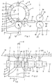
- Fig. 1 die Vorrichtung in Seitenansicht,
- Fig. 2 die Vorrichtung in Draufsicht.
- 1 shows the device in side view,
- Fig. 2 shows the device in plan view.
Nach den Fig. 1 und 2 hat eine Halterung 1 eine Haltefläche 2, an der eine Wickeleinrichtung 3 angeordnet ist. Die Wickeleinrichtung 3 hat eine kreisringförmig ausgebildete Trägerplatte 4, die kreisringförmig am Außenumfang des zu wickelnden Rohres angeordnete, frei drehbare Stützrollen 5 trägt, deren Drehachsen 6 zueinander parallel sind. Die durch den Mittelpunkt M des von den Drehachsen 6 der Stützrollen 5 gebildeten Kreises und parallel zu den Drehachsen 6 der Stützrollen verlaufende Mittelachse 7 ist gleich der mittleren Längsachse des zu wickelnden Rohres.1 and 2, a holder 1 has a
An der Einlaufstelle des zu wickelnden Bandes 8 in die Wickeleinrichtung 3 sind zwei Einlaufrollen 9 und 10 angeordnet, die antreibbar sind und die an den beiden Breitseiten des Bandes angreifen. Die innere Einlaufrolle 9 ist innerhalb der Wickeleinrichtung 3 angeordnet, während die äußere Einlaufrolle 10 außerhalb der Wickeleinrichtung angeordnet ist. Die Einlaufrollen sind um senkrecht zur Haltefläche 2 stehende Drehachsen 11 drehbar und von einer nicht gezeigten Antriebsvorrichtung antreibbar. Die innere Einlaufrolle 9 weist eine kleinere Umfangsgeschwindigkeit als die äußere Einlaufrolle 10 auf.At the entry point of the
Wie insbesondere die Fig. 2 erkennen läßt, weist die Trägerplatte 4 eine zur Mittelachse 7 in einem Winkel von 90° vermehrt um den Steigungswinkel α des zu wickelnden Rohres verlaufende Anlagefläche 12 auf, die an der Haltefläche 2 anliegt, so daß die Drehachsen 6 der Stützrollen 5 bzw. die Mittelachse 7 die durch die Drehachsen 11 der Einlaufrollen 9 und 10 bestimmte, mit 13 bezeichnete Ebene in dem Steigungswinkel a schneiden. Weiter ist die Trägerplatte 4 derart auf der Haltefläche 2 angeordnet, daß die Mittelachse 7 die durch die Drehachsen 11 der Einlaufrollen 9, 10 bestimmte, mit 13 bezeichnete Ebene in der Schnittlinie dieser Ebene mit der durch die Mitte der Einlaufrollen 9 und 10, senkrecht zu den Drehachsen 11 der Einlaufrollen verlaufen, mit 14 bezeichneten Ebene schneidet. Wie Fig. 2 weiter erkennen läßt, verläuft das zu wickelnde Band 8 symmetrisch zu dieser mit 14 bezeichneten Ebene.As can be seen in particular in FIG. 2, the
Wie die Fig. 1 erkennen läßt, ist die Trägerplatte 4 in der mit dem Pfeil 15 bezeichneten Wickelrichtung um die Mittelachse 7 derart gedreht angeordnet, daß die mit 16 bezeichnete Schnittlinie der Anlagefläche 12 mit einer zur Mittelachse 7 senkrechten Ebene (in Fig. 2 beispielsweise die mit 17 bezeichnete Ebene) die durch die Drehachsen 11 der Einlaufrollen 9 und 10 verlaufende, mit 13 bezeichnete Ebene in einem spitzen Schnittwinkel ßschneidet.As can be seen in FIG. 1, the
Im Abstand vor der Einlaufstelle der Wickeleinrichtung 3 sind an der Halterung 1 zwei Antriebsrollen 18 angeordnet, die ebenfalls an den Breitseiten des Bandes 8 angreifen. Die antreibbaren Antriebsrollen 18 sind um zur Haltefläche 2 senkrechte Drehachsen 19 drehbar, wobei die durch die Drehachsen 19 verlaufende, mit 20 bezeichnete Ebene parallel zu der mit 13 bezeichneten Ebene durch die Drehachsen 11 der Einlaufrollen 9 und 10 verläuft. Weiterhin ist zwischen den Antriebsrollen 18 und Einlaufrollen 9 und 10 eine Bandführung 21 angeordnet. Die Umfangsgeschwindigkeit der Antriebsrollen 18 ist größer als die Umfangsgeschwindigkeit der äußeren Einlaufrolle 10.At a distance from the entry point of the
Zwischen Bandführung 21 und Einlaufrollen 9 und 10 ist eine Biegerolle 22 angeordnet, die um eine zu der Anlagefläche 2 senkrechte Drehachse 23 drehbar ist und in Richtung zur Mittelachse 7 verschiebbar und festlegbar an der Halterung angeordnet ist. Die Biegerolle 22 ist dabei derart eingestellt, daß sie die Verbindungslinie zwischen der Einlaufstelle und der Bandführung 21 in Richtung auf die Mittelachse 7 überragt, wie dies in Fig. 1 dargestellt ist.Between the
Bei der Herstellung eines Rohres durch schraubenlinienförmiges Wickeln des Bandes 8 wird das Band zunächst in Richtung des mit 24 bezeichneten Pfeiles den Antriebsrollen 18 zugeführt, die es durch die Bandführung 21 und über die Biegerolle 22 dem Einlaufrollenpaar 9 und 10 der Wickeleinrichtung 3 zuführen. In der Wickeleinrichtung wird das Band 8 schraubenlinienförmig zu einem Rohr gewickelt, wobei die Einlaufrollen 9 und 10 die Verbindung des zulaufenden Bandes mit dem bereits gewickelten Rohr herstellen. Das gewickelte Rohr wird in Richtung des mit 25 bezeichneten Pfeiles aus der Wickeleinrichtung 3 abgezogen.In the manufacture of a tube by helically winding the
Dadurch, daß die Umfangsgeschwindigkeit der inneren Einlaufrolle kleiner als die Umfangsgeschwindigkeit der äußeren Einlaufrolle ist, wird eine sichere Führung des Bandes zwischen den Einlaufrollen gewährleistet und das zu wikkeinde Band fest an die Stützrollen 5 der Wickeleinrichtung 3 angedrückt, so daß das Band bzw. das Rohr sicher in der Wickeleinrichtung 3 gehalten wird und hohe Arbeitsgeschwindigkeiten möglich sind. Diese Wirkung wird noch dadurch verstärkt, daß die Umfangsgeschwindigkeit der Antriebsrollen 18 größer als die Umfangsgeschwindigkeit der äußeren Einlaufrolle 10 ist.Characterized in that the peripheral speed of the inner infeed roller is less than the peripheral speed of the outer infeed roller, a secure guiding of the belt between the infeed rollers is ensured and the belt to be wikkeinde pressed firmly against the
Gleiches bewirkt auch die Drehung der Trägerplatte 4 um die Mittelachse 7 um den Winkel jJ, wodurch die dem Einlaufrollenpaar 9 und 10 folgende Stützrolle 5 etwas nach oben geneigt wird. Durch die Biegerolle 22 erfährt das zu wikkelnde Band bereits eine geringe Vorbiegung, so daß die Biegearbeit in der Wickeleinrichtung verringert wird.The same effect is caused by the rotation of the
Als vorteilhaft hat es sich herausgestellt, daß der Schlupf zwischen den beiden Einlaufrollen 9 bzw. 10 bzw. zwischen der äußeren Einlaufrolle 10 und den Antriebsrollen 18, 18 0,2 bis 0,5 mm pro Umdrehung der inneren Einlaufrolle 9 bzw. der Antriebsrollen 18, 18 beträgt. Als günstig wurde für den Schnittwinkel ,B ein Wert von 0,5 bis 1,5° gefunden. Die kreisringförmig ausgebildete Trägerplatte 4 ist an der Haltefläche 2 der Halterung 1 lösbar befestigt, so daß zur Herstellung eines Rohres mit einem anderen Durchmesser eine andere Wickeleinrichtung mit dem entsprechenden Durchmesser an der Halterung 1 befestigbar ist. Dadurch, daß die innere Einlaufrolle 9 einen sehr kleinen Durchmesser aufweist, wird nicht nur die Biegearbeit erleichtert, sondern ist es auch möglich, Rohre mit sehr kleinem Durchmesser herzustellen.It has been found to be advantageous that the slip between the two
Claims (9)
Priority Applications (1)
| Application Number | Priority Date | Filing Date | Title |
|---|---|---|---|
| AT80105664T ATE7464T1 (en) | 1980-06-16 | 1980-09-20 | DEVICE FOR PRODUCTION OF PIPES BY HELICAL WINDING OF A PREFERABLY CORRUGATED STRIP. |
Applications Claiming Priority (2)
| Application Number | Priority Date | Filing Date | Title |
|---|---|---|---|
| DE3022575 | 1980-06-16 | ||
| DE19803022575 DE3022575C3 (en) | 1980-06-16 | 1980-06-16 | Device for producing pipes by helically winding a preferably corrugated strip |
Publications (3)
| Publication Number | Publication Date |
|---|---|
| EP0042011A2 EP0042011A2 (en) | 1981-12-23 |
| EP0042011A3 EP0042011A3 (en) | 1982-04-14 |
| EP0042011B1 true EP0042011B1 (en) | 1984-05-16 |
Family
ID=6104763
Family Applications (1)
| Application Number | Title | Priority Date | Filing Date |
|---|---|---|---|
| EP80105664A Expired EP0042011B1 (en) | 1980-06-16 | 1980-09-20 | Device for the production of tubes by helically winding a preferably corrugated strip |
Country Status (2)
| Country | Link |
|---|---|
| EP (1) | EP0042011B1 (en) |
| AT (1) | ATE7464T1 (en) |
Families Citing this family (2)
| Publication number | Priority date | Publication date | Assignee | Title |
|---|---|---|---|---|
| DE3540125C3 (en) * | 1985-11-13 | 1997-05-07 | Hahn Fritz Gmbh Co Kg | Method and device for producing a corrugated tube by helically winding a corrugated, thin strip, preferably a steel strip |
| GB2433453B (en) | 2005-12-23 | 2010-08-11 | Iti Scotland Ltd | An apparatus for and method of manfacturing helically wound structures |
Family Cites Families (3)
| Publication number | Priority date | Publication date | Assignee | Title |
|---|---|---|---|---|
| DE1602342A1 (en) * | 1967-05-11 | 1971-08-26 | Protol S A | Tube with a screw-shaped seam |
| DE2154438C3 (en) * | 1971-11-02 | 1980-12-18 | Institut Elektrosvarki Imeni E.O. Patona Akademii Nauk Ukrainskoj Ssr, Kiew (Sowjetunion) | Seam pipe mill |
| DE2754483C2 (en) * | 1976-12-23 | 1982-11-18 | Emil 6603 Sulzbach Siegwart | Device for the production of spiral tubes |
-
1980
- 1980-09-20 AT AT80105664T patent/ATE7464T1/en not_active IP Right Cessation
- 1980-09-20 EP EP80105664A patent/EP0042011B1/en not_active Expired
Also Published As
| Publication number | Publication date |
|---|---|
| ATE7464T1 (en) | 1984-06-15 |
| EP0042011A2 (en) | 1981-12-23 |
| EP0042011A3 (en) | 1982-04-14 |
Similar Documents
| Publication | Publication Date | Title |
|---|---|---|
| DE2163649C2 (en) | Device for the production of helically corrugated wires | |
| DE2327846C3 (en) | Device for dressing a grinding wheel | |
| EP0515802B1 (en) | Apparatus for making helically seamed tubes from metal strip | |
| EP0042011B1 (en) | Device for the production of tubes by helically winding a preferably corrugated strip | |
| DE1814632B2 (en) | Device for bending a flat, comb-like, pronged wire strip in its transverse direction into the shape of a slotted tube | |
| DE2642583A1 (en) | WELDING MACHINE FOR JOINING STRIP STEEL SECTIONS OR ROLLS | |
| DE2210055C3 (en) | Method of joining adjacent edges of metal sheets by folding | |
| DE3022575C2 (en) | ||
| DE1452409A1 (en) | Rotary and feed drive for metallic, helical heat exchanger tubes to be wound with a wire helix | |
| DE2009509A1 (en) | Machine for the continuous Her position of reinforcement cages for reinforced concrete piles, masts or the like | |
| CH620607A5 (en) | Device for the production of helically seamed and perforated tubes | |
| DE2806973C2 (en) | Device for applying strand sections to a body of revolution | |
| DE2428111A1 (en) | METHOD AND DEVICE FOR SAWING WORK PIECES | |
| DE3447183C2 (en) | ||
| DE2255864A1 (en) | DEVICE FOR CUTTING RINGS FROM A HOSE OR THE LIKE | |
| DE2249312B2 (en) | Method and device for manufacturing a stand for dynamoelectric machines | |
| DE3116990A1 (en) | MACHINE FOR PRODUCING SCREW-SHAPED TUBE TUBES | |
| DE2525289A1 (en) | Straightening unit on bar peeling machine - has roll centres and angles adjustable and rolls replaceable | |
| DE4012029A1 (en) | DEVICE FOR DRAWING TUBE MATERIAL OR THE LIKE | |
| DE4124618C2 (en) | Device for the production of welded profile tubes | |
| DE19709733A1 (en) | Rotating straightening device for wire | |
| DE1629770C2 (en) | Device for producing a glass fiber reinforced plastic pipe or pipe-like molded body | |
| AT164284B (en) | Thread rolling machine | |
| DE1948672C (en) | Stripping device for the strand emerging from a casting wheel | |
| DE3118960C2 (en) | Grinding device for the disc-shaped knives of a fur cutting device |
Legal Events
| Date | Code | Title | Description |
|---|---|---|---|
| PUAI | Public reference made under article 153(3) epc to a published international application that has entered the european phase |
Free format text: ORIGINAL CODE: 0009012 |
|
| AK | Designated contracting states |
Designated state(s): AT BE CH FR GB IT LU NL SE |
|
| PUAL | Search report despatched |
Free format text: ORIGINAL CODE: 0009013 |
|
| AK | Designated contracting states |
Designated state(s): AT BE CH FR GB IT LU NL SE |
|
| 17P | Request for examination filed |
Effective date: 19820423 |
|
| R17P | Request for examination filed (corrected) |
Effective date: 19820423 |
|
| ITF | It: translation for a ep patent filed |
Owner name: DE DOMINICIS & MAYER S.R.L. |
|
| GRAA | (expected) grant |
Free format text: ORIGINAL CODE: 0009210 |
|
| AK | Designated contracting states |
Designated state(s): AT BE CH FR GB IT LI LU NL SE |
|
| REF | Corresponds to: |
Ref document number: 7464 Country of ref document: AT Date of ref document: 19840615 Kind code of ref document: T |
|
| ET | Fr: translation filed | ||
| PLBE | No opposition filed within time limit |
Free format text: ORIGINAL CODE: 0009261 |
|
| STAA | Information on the status of an ep patent application or granted ep patent |
Free format text: STATUS: NO OPPOSITION FILED WITHIN TIME LIMIT |
|
| 26N | No opposition filed | ||
| ITTA | It: last paid annual fee | ||
| EPTA | Lu: last paid annual fee | ||
| EAL | Se: european patent in force in sweden |
Ref document number: 80105664.9 |
|
| PGFP | Annual fee paid to national office [announced via postgrant information from national office to epo] |
Ref country code: GB Payment date: 19980817 Year of fee payment: 19 |
|
| PGFP | Annual fee paid to national office [announced via postgrant information from national office to epo] |
Ref country code: LU Payment date: 19980820 Year of fee payment: 19 Ref country code: BE Payment date: 19980820 Year of fee payment: 19 |
|
| PGFP | Annual fee paid to national office [announced via postgrant information from national office to epo] |
Ref country code: SE Payment date: 19980821 Year of fee payment: 19 Ref country code: NL Payment date: 19980821 Year of fee payment: 19 Ref country code: FR Payment date: 19980821 Year of fee payment: 19 Ref country code: CH Payment date: 19980821 Year of fee payment: 19 Ref country code: AT Payment date: 19980821 Year of fee payment: 19 |
|
| PG25 | Lapsed in a contracting state [announced via postgrant information from national office to epo] |
Ref country code: LU Free format text: LAPSE BECAUSE OF NON-PAYMENT OF DUE FEES Effective date: 19990920 Ref country code: GB Free format text: LAPSE BECAUSE OF NON-PAYMENT OF DUE FEES Effective date: 19990920 Ref country code: AT Free format text: LAPSE BECAUSE OF NON-PAYMENT OF DUE FEES Effective date: 19990920 |
|
| PG25 | Lapsed in a contracting state [announced via postgrant information from national office to epo] |
Ref country code: SE Free format text: THE PATENT HAS BEEN ANNULLED BY A DECISION OF A NATIONAL AUTHORITY Effective date: 19990929 |
|
| PG25 | Lapsed in a contracting state [announced via postgrant information from national office to epo] |
Ref country code: LI Free format text: LAPSE BECAUSE OF NON-PAYMENT OF DUE FEES Effective date: 19990930 Ref country code: CH Free format text: LAPSE BECAUSE OF NON-PAYMENT OF DUE FEES Effective date: 19990930 Ref country code: BE Free format text: LAPSE BECAUSE OF NON-PAYMENT OF DUE FEES Effective date: 19990930 |
|
| BERE | Be: lapsed |
Owner name: FRITZ HAHN K.G. Effective date: 19990930 |
|
| PG25 | Lapsed in a contracting state [announced via postgrant information from national office to epo] |
Ref country code: NL Free format text: LAPSE BECAUSE OF NON-PAYMENT OF DUE FEES Effective date: 20000401 |
|
| GBPC | Gb: european patent ceased through non-payment of renewal fee |
Effective date: 19990920 |
|
| EUG | Se: european patent has lapsed |
Ref document number: 80105664.9 |
|
| REG | Reference to a national code |
Ref country code: CH Ref legal event code: PL |
|
| PG25 | Lapsed in a contracting state [announced via postgrant information from national office to epo] |
Ref country code: FR Free format text: LAPSE BECAUSE OF NON-PAYMENT OF DUE FEES Effective date: 20000531 |
|
| NLV4 | Nl: lapsed or anulled due to non-payment of the annual fee |
Effective date: 20000401 |
|
| REG | Reference to a national code |
Ref country code: FR Ref legal event code: ST |