EP0042004B1 - Gunnery simulation system - Google Patents
Gunnery simulation system Download PDFInfo
- Publication number
- EP0042004B1 EP0042004B1 EP81900248A EP81900248A EP0042004B1 EP 0042004 B1 EP0042004 B1 EP 0042004B1 EP 81900248 A EP81900248 A EP 81900248A EP 81900248 A EP81900248 A EP 81900248A EP 0042004 B1 EP0042004 B1 EP 0042004B1
- Authority
- EP
- European Patent Office
- Prior art keywords
- bullet
- indicia
- aircraft
- simulated
- target
- Prior art date
- Legal status (The legal status is an assumption and is not a legal conclusion. Google has not performed a legal analysis and makes no representation as to the accuracy of the status listed.)
- Expired
Links
Images



Classifications
-
- H—ELECTRICITY
- H01—ELECTRIC ELEMENTS
- H01M—PROCESSES OR MEANS, e.g. BATTERIES, FOR THE DIRECT CONVERSION OF CHEMICAL ENERGY INTO ELECTRICAL ENERGY
- H01M4/00—Electrodes
- H01M4/02—Electrodes composed of, or comprising, active material
- H01M4/36—Selection of substances as active materials, active masses, active liquids
- H01M4/48—Selection of substances as active materials, active masses, active liquids of inorganic oxides or hydroxides
- H01M4/56—Selection of substances as active materials, active masses, active liquids of inorganic oxides or hydroxides of lead
- H01M4/57—Selection of substances as active materials, active masses, active liquids of inorganic oxides or hydroxides of lead of "grey lead", i.e. powders containing lead and lead oxide
-
- F—MECHANICAL ENGINEERING; LIGHTING; HEATING; WEAPONS; BLASTING
- F41—WEAPONS
- F41G—WEAPON SIGHTS; AIMING
- F41G3/00—Aiming or laying means
- F41G3/26—Teaching or practice apparatus for gun-aiming or gun-laying
- F41G3/2605—Teaching or practice apparatus for gun-aiming or gun-laying using a view recording device cosighted with the gun
-
- F—MECHANICAL ENGINEERING; LIGHTING; HEATING; WEAPONS; BLASTING
- F41—WEAPONS
- F41G—WEAPON SIGHTS; AIMING
- F41G3/00—Aiming or laying means
- F41G3/26—Teaching or practice apparatus for gun-aiming or gun-laying
- F41G3/2616—Teaching or practice apparatus for gun-aiming or gun-laying using a light emitting device
- F41G3/2622—Teaching or practice apparatus for gun-aiming or gun-laying using a light emitting device for simulating the firing of a gun or the trajectory of a projectile
- F41G3/2644—Displaying the trajectory or the impact point of a simulated projectile in the gunner's sight
-
- H—ELECTRICITY
- H01—ELECTRIC ELEMENTS
- H01M—PROCESSES OR MEANS, e.g. BATTERIES, FOR THE DIRECT CONVERSION OF CHEMICAL ENERGY INTO ELECTRICAL ENERGY
- H01M4/00—Electrodes
- H01M4/02—Electrodes composed of, or comprising, active material
- H01M4/64—Carriers or collectors
- H01M4/70—Carriers or collectors characterised by shape or form
- H01M4/76—Containers for holding the active material, e.g. tubes, capsules
- H01M4/765—Tubular type or pencil type electrodes; tubular or multitubular sheaths or covers of insulating material for said tubular-type electrodes
-
- Y—GENERAL TAGGING OF NEW TECHNOLOGICAL DEVELOPMENTS; GENERAL TAGGING OF CROSS-SECTIONAL TECHNOLOGIES SPANNING OVER SEVERAL SECTIONS OF THE IPC; TECHNICAL SUBJECTS COVERED BY FORMER USPC CROSS-REFERENCE ART COLLECTIONS [XRACs] AND DIGESTS
- Y02—TECHNOLOGIES OR APPLICATIONS FOR MITIGATION OR ADAPTATION AGAINST CLIMATE CHANGE
- Y02E—REDUCTION OF GREENHOUSE GAS [GHG] EMISSIONS, RELATED TO ENERGY GENERATION, TRANSMISSION OR DISTRIBUTION
- Y02E60/00—Enabling technologies; Technologies with a potential or indirect contribution to GHG emissions mitigation
- Y02E60/10—Energy storage using batteries
Definitions
- This invention relates to a gunnery simulation system for use, with an aircraft, in gunfire training and evaluation of accuracy in simulated gunfire.
- a gunnery simulating system for use with an aircraft, for gunfire training and evaluation of simulated firing accuracy, comprises a sighting panel presenting a field of view, including a target, to a gun operator; means for generating data signals describing the roll rate p, pitch rate q, yaw rate r, lift acceleration A w , and true air speed V a , of the aircraft, the gun angle of attack Q g, and the relative air density p/p o ; display means for presenting and for displaying simulated bullet indicia on said sighting panel superimposed on said field of view; means controlled by said operator for simulating the firing of the guns of the aircraft at said target; and means for controlling the operation of said display means to present said simulated bullet indicia responsive to said simulated firing of the guns of the aircraft and to display simulated trajectory paths for each of said presented simulated bullet indicia in said field of view in response to said
- the present invention can be seen to employ the principle of firing simulated bullets at real targets. This is accomplished by projecting images or "pips" which track the trajectory of hypothetical bullets on the head-up display (HUD) used by the gun operator (pilot) of the attacking aircraft. This permits the pilot to observe the trajectory of the simulated bullets as the pips move toward the target in a manner essentially similar to the way tracer rounds are used in the instance of live ammunition.
- HUD head-up display
- the pips may be displayed only within the gun camera system and recorded for later use in evaluating pilot performance. This may be done by superimposing the pip display on the field of view of gun camera 72 (Fig. 3), which may or may not be positioned to record the actual field of view of the pilot.
- the displayed "pips" do not directly represent the bullets themselves, but rather two pips are projected for each bullet and the bullet position (which need not be actually displayed) is mid-way between the two pips.
- This principle is illustrated in Fig. 1 wherein pips (b11, b 12' ) are equidistant from the simulated trajectory path of the first simulated round fired after the pilot depresses the trigger. The position of the round itself (circled dot) is mid-way between the pips (b 11 , b 12 ).
- Pips (b 21 , b 22 ), (b 31 , b 32 ) and (b 4 ,, b 42 ) are equidistant from the simulated second, third, and fourth fired rounds, respectively.
- the target T is shown with respect to the pairs of pips and the distance between a pair of pips is selected to be equal to a known dimension of the target, e.g., aircraft wingspan.
- the pips are displayed to appear to converge as the simulated round position moves further along its trajectory path from the gun muzzle.
- the point when the display round is at target range is determined by observing the lateral separation between the pip pair representing the round.
- the round is in the plane of the target.
- This use of dual pips enables the pilot, or a person evaluating the pilot's performance through later review of videotape or film pro- by camera 72, to determine the point at which the bullets pass through the plane of the target. Rounds which overlie the target image at this point are "hits".
- This simulated bullet display system therefore, enables a more accurate and useful evaluation of a pilot's performance than the traditional use of live tracer rounds and simulated target techniques.
- the degree of accuracy with which target range can be measured by this system is limited primarily by the film resolution of the videotape since a "hit" is determined visually by the equality of pip spacing and selected target dimension.
- camera film resolution is about 0.5 milliradians (mr) under normal lighting conditions.
- Fig. 2 are presented a set of graphs A, B, C for the following assumed conditions.
- the true airspeed of the "firing" aircraft is about 450 knots (about 800 kilometers per hour (800 km/hr)).
- the "target” aircraft is an F-4 fighter plane.
- the altitude of the encounter between the two aircraft is 3000 meters (m).
- the horizontal axis in Fig. 2 indicates range, i.e. separation of the two aircraft, in meters (m).
- the vertical axis indicates angle in milliradians (mr) as viewed from the firing aircraft.
- Graph A reflects the angle, in mr, subtended by the target aircraft, at an aspect angle of 30°, as a function of range.
- Graph B indicates the bullet-miss-error (in mr) as a function of range, as calculated by typical aircraft radar computation, which is subject to computation inaccuracy as to distance to the target of 10 meters, equivalent to a 2 mr inaccuracy.
- Graph C indicates the bullet-miss error in mr as calculated by the so-called "stadia metric method" which is subject to an inaccuracy of 0.5 mr due to the mentioned 0.5 mr camera film resolution. It is apparent that the stadia metric method is more accurate than a typical aircraft radar in computing target range for distances up to 500 meters. The uncertainty in bullet impact error is within typical target dimensions out to a range of about 800 meters.
- the symbol ADL denotes the so-called armament datum line.
- the point in time when each simulated round passes through the target range can be determined in flight from known ballistic parameters and the motion characteristics of the aircraft at the time of firing. This point in time can be displayed directly to the pilot and recorded on the videotape or other film.
- the stadia method then can be used as a more accurate assessment of error in short ranges without radar lock-on, i.e., less than 500 metres, and as a backup assessment at longer ranges when the recorded data is being analyzed.
- the evaluation display can be flight tested simply by reducing the target wingspan to zero and firing live tracers under conditions where they can be easily observed and photographed. There should be a one-to-one correspondence between the actual and simulated rounds as the aircraft is maneuvered while the rounds are in flight. In normal operating conditions, this also provides the pilot with an effective method for checking the boresight accuracy of the aircraft guns.
- the pilot When the gunnery evaluation display is included in the same HUD used by the pilot for gun aiming, the pilot is provided with a sense of having fired a weapon at the target during a training exercise, and provided a useful degree of immediate feedback of results. If, however, it is determined that the pilot would be distracted by including the evaluation display in the normal gunsight, then the simulated rounds could be superimposed on the videotape produced by the gunsight TV camera.
- Fig. 3 shows, in block diagram form, the gunsight system in accordance with a preferred embodiment of the invention.
- the pilot (gun operator), located at B, is presented with a field of view through a combining glass panel 22 arranged in accordance with a conventional HUD configuration.
- the pilot's field of view includes the line of sight 11 to the target.
- the display means for presenting and displaying simulated bullet pips or trajectory indicia comprises a sighting display unit 24, including a cathode ray tube (CRT) 26 and collimating optics 27, operating to project sighting indicia onto the pilot's field of view via the combining glass 22.
- the collimating optics 27 serve to focus the indicia images so that they appear to the pilot to be emanating from infinity, i.e., from the area of the target.
- This collimating arrangement is well-known in connection with HUD systems and operates to eliminate parallax problems and permits the pilot the freedom to move his head within the sight field of view without degrading the accuracy of the system.
- the display unit 24 projects bullet trajectory indicia or pips in accordance with control signals received from a controlling means 25 including a symbol generator 28 and a digital computer 30.
- the latter receives inputs through an analog-to-digital (A/D) converter unit 32 from means for generating data signals describing the motion of the aircraft and including a plurality of data input sources 34, 36 and 38.
- A/D analog-to-digital
- Air data generator 34 supplies signals to A/D unit 32 over lines 52, 54 and 56 representing, respectively, aircraft true air speed V a , gun angle of attackQg, and relative air density p/p o . These signals are encoded by A/D converter unit 32 and are fed to computer 30 via data bus 64.
- An inertial data generator 36 supplies signals representing own aircraft lift acceleration A W , roll rate p, pitch rate q, and yaw rate r, on lines 58, 60, 62 and 64, respectively. These signals are also encoded by A/D converter 32 and fed to computer 30 via a data bus 64.
- a means controlled by the operator for simulating the firing of the aircraft gun comprises a trigger subsystem 38 which supplies signals T representing the actuation of the gun trigger by the pilot and AS corresponding to the identification of the type of the target.
- the signals T could be a single pulse indicating the firing of a single bullet or, more likely, a series of pulses corresponding to a series of bullets fired in a sequence at the target. These signals are supplied to A/D converter 32 and fed to computer 30 over data bus 64.
- a videotape camera 72 is positioned to record the view of the pilot through his sighting panel 22.
- the target and approaching stream of bullet trajectory indicia or pips can be recorded on videotape for later analysis and evaluation.
- Fig. 4 geometrically represents the components of the range vector R * and bullet velocity vector V b which describes the trajectory of the bullet at any point in time after firing.
- the position of the firing aircraft is indicated by the point of origin a/c and the components u, v and w represent unit vectors along the axes of the three spatial dimensions realtive to the point of origin a/c.
- Unit vector v is along the right wing of the aircraft
- unit vector u is along the gun bore axis
- unit vector w is in a direction normal to the wings and, by convention, downward.
- the unit vector s is along the line of sight to the target.
- the vector V m is the multiplication product of unit vector u and scalar muzzle velocity (speed) V m .
- the true airspeed of the aircraft is defined by the vector V a .
- Equation (42) is therefore an appropriate correction to be added to the traverse bullet angle.
- Traverse angles (22) and (23) may be approximated by the argument of the arc tan function with sufficient accuracy.
- Table 1 lists the error due to omitting the third order term in approximating tan -1 X with X.
- the third order term is apparently necessary for elevation angles but not for traverse angles.
- the angular position of the bullet at target range is displayed in the form of a six milliradian circle (dispersion) at the time that bullet range is equal to target range.
- a somewhat simpler, and sufficiently accurate approach is to compare the u axis component of bullet position with the u axis component of target range, i.e., Where:
- the mentioned computer (iteration time interval At of 0.02 sec. produces a 4 mr step between successive bullet angles. This is not a negligible error, although it is small.
- Fig. 5 shows in more detail the computer 30 of Fig. 3.
- the computer 30 comprises a central processor unit 102 interconnected with a timing circuit 104 and a memory 106.
- the central processor unit 102 receives the outputs from air data generator 34, inertial data generator 36 and trigger subsystem 38 over bus 64 through input/output control 108.
- the CPU 102 passes information from memory 106 to bus 66 and to symbol generator 28 through the input/output control 108. This information comprises the angular coordinates for the pairs of bullet trajectory indicia or pips displayed on the combining glass 22 by the sighting display unit 24.
- a suitable central processor unit is the MCP701A digital display processor manufactured by General Electric Co.
- the angular coordinates of the pairs of pips are generated by central processor unit 102 by means of the above-discussed equations.
- the central processor 102 is programmed to perform the necessary operations.
- Figs. 6a and 6b show the program for accomplishing this task.
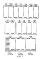
- Fig. 7 shows the data tables resident in memory 106 for storing the data necessary to perform the calculations.
- Fig. 8 shows the display tables also resident in memory 106 for storing the angular coordinate of the pairs of pips.
- the tables in Fig. 7 store data concerning and describing the condition of each simulated bullet.
- each table has ten entries and, thus, the system is capable of simultaneously displaying ten simulated bullets in the form of ten pairs of bullet trajectory indicia, i.e., ten pairs of pips.
- the information stored in the tables comprises:
- the quantities RVV, RW1, and RWW are both double precision, meaning that two words of storage are provided for each of these quantities.
- Fig. 6a the operation of the firing evaluation and display system is initiated by setting the A register and the B register to PG35. K is set to one and KBUT is set to NBUT. The next step is to fetch T(K) which in this instance would be T(1 This quantity is checked for zero and, if it is zero, then that entry in the bullet table is not active and no update of a bullet position is required for that entry. In such case, KBUT is decremented by one and checked to see if it is zero. If KBUT is zero then all the entries in the bullet table have been processed and processing continues to update any remaining display angular coordinates.
- T(K) is set to the quantity T(K)-1.
- the time of flight is computed as The quantity 0.02 is chosen because the system is set to display 1-10 bullets simultaneously. Presently, with ten bullets a twenty millisecond interrupt time is the minimum and, thus, the quantity ITMAX-T(K) specifies the number of iterations performed and the quantity 0.02 corresponds to the time between iterations.
- the new bullet position for bullet K is calculated according to the foregoing equations and the results are stored in the Kth entry of the bullet tables shown in Fig. 7.
- the pointer into the number of bullets processed, KBUT is decremented by one and checked to see if it is zero. If it is not, the A register is incremented by one, the B register is incremented by two and K is incremented by one.
- the next entry in the bullet table is processed in the above-described manner and the same procedures are iteratively performed until all entries in the bullet table have been accessed and new bullet positions calculated and stored for each active entry.
- the A register and B register are reset to PG35, the C register is set to DEND, K is reset to one and KBUT is set to NBUT.
- the processing continues to update the angular coordinates for each bullet trajectory indicia or pair of bullet pips stored in the bullet display table of Fig. 8.
- the x and y positions for each pip of a pair of pips representing the simulated bullet is compared to maximum display parameters to insure that the computer 30 does not generate angular display coordinates which are outside of the display range of display unit 24. If such is the case, further processing for that entry in the bullet table is bypassed. If, however, the x and y coordinates are within the display limits, the angular display coordinates stored in the display table shown in Fig. 8 corresponding to this bullet position in the bullet table of Fig. 7 are updated with the newly calculated bullet position for that particular bullet entry.
- the display table of Fig. 8 utilizes six words of storage for each bullet. These six words store, in order, POSX, POSY, corresponding to ⁇ v and ⁇ w1 , respectively.
- a JM5 instruction meaning to jump five words ahead in processing, POSX, POSY, corresponding to ⁇ v and A,,2, respectively, and another JM5 instruction.
- the bullet display table shown in Fig. 8 reflects two active bullet positions, i.e., bullet 1 and bullet 2 and eight inactive bullet positions 3-10.
- the first word of storage is a JMP6 instruction which results in bypassing all processing for that entry in the bullet display table.
- the entry in the bullet display table has been updated with new angular coordinates reflecting the newly determined bullet position, the entry T(K) is checked to see if it is equal to one. If it is, that entry in the bullet table is made inactive by setting T(K) equal to zero. This is done because the time of flight for the simulated bullet corresponding to that entry in a bullet table is equal to the maximum time of flight within the system and, thus, the pair of pips for that particular bullet entry will not longer be displayed.
- the operations following (1) the BIPAS determination, (2) a determination that T(K) is equal to one, and (3) the setting of T(K) to zero are all the same.
- These operations include incrementing the A register by one, incrementing the B register by two, incrementing the C register by six, incrementing K by one and decrementing KBUT by one. If KBUT is not equal to zero then the next entry in the bullet table is processed in the foregoing manner in order to update its corresponding entry in the bullet display table.
- the END routine is loaded in the display table and the symbol generator is permitted to transfer the angular coordinates of each pair of pips to the display unit for display on sighting panel 22.
- the manner in which the display of the pips is accomplished in response to the angular display coordinates is well-known and need not be further discussed.
- the processing operations set forth in Fig. 6b are performed in response to the firing of another simulated bullet by the gun operator or pilot.
- First the trigger flag, TRFLG is checked to see if it equals one. If it does not, then no new simulated bullet has been fired and processing returns to the bullet table updating routines set forth in Fig. 6a. If TRFLG is equal to one then another trigger flag TRFLG1 is also checked to see if it equals one. If it does, the bullet counter BSC is decremented by one and checked to see if it equals zero. If it is not equal to zero then a sufficient time has not passed since the previous bullet has been entered into the system and processing returns to the bullet position update routines in Fig. 6a.
- BSC is reset, i.e., set to six in this instance, and a new entry is placed in the bullet tables shown in Fig. 7.
- the entry of a new, simulated bullet into the system is accomplished by scanning the bullet table for zero entries in the T(K) positions. If a zero entry is found, ITMAX is loaded into the T(K) storage position for the detected position in the bullettable. Also, intialization of certain variables is performed at this time, and the instantaneous values of the air data sensors and inertial data sensors are stored in appropriate form in that entry of the bullet table. After these initialization steps are performed, processing returns to the bullet updating routines of Fig. 6a.
- a pilot sitting at B sights a target aircraft in his field of view 11.
- the pilot operates the trigger subsystem by actuating the aircraft selector and the trigger for the guns of the aircraft.
- the aircraft selector generates an aircraft selector pulse AS identifying the type of target aircraft and the trigger subsystem generates trigger pulses T for each depression or the continual depression of the trigger. These signals are provided to the analog-to-digital converter 32.
- the air data generator 34 is supplying instantaneous values for the velocity of the aircraft, V a , the gun angle of attack, Q g, and relative air density p. These signals are similarly encoded by the analog-to-digital converter 32.
- the inertial data generator 36 is also supplying instantaneous values for the aircraft lift acceleration A w , roll rate p, pitch rate q, and yaw rate r. Again, these signals are encoded by the analog-to-digital converter 32 and, with the other inputs, are supplied to computer 30.
- the computer 30 creates an entry in a bullet table stored in its memory for each simulated bullet fired by the pilot. All necessary information for computing and displaying the trajectory of the simulated bullet is stored in its corresponding entry in the bullet table. From this data, the computer computes a range vector and velocity vector for each simulated bullet. Angular display coordinates are generated from the range vector and velocity vector such that a pair of bullet trajectory indicia or visible pips can be displayed in a manner that represents the trajectory of the simulated bullet over a particular time span. The equations necessary for computing the range vector and velocity vector as well as the angular display coordinates have been previously set forth.
- the angular display coordinates for the pips are stored in the bullet display table.
- the computer transfers the contents of the bullet display table to the symbol generator 28 which controls the display unit 24 in a manner that will project the bullet trajectory indicia or pips corresponding to each simulated bullet on combining glass 22. This superimposes the pips on the field of view of the pilot so that the relative position of the pips and the target aircraft can be observed.
- a camera 72 is coupled to the display unit 24 by control lines 74 such that the camera can record on videotape the superimposed image of the pips and target much as they are actually seen by the pilot.
- the computer continually updates the trajectory for each pair of display pips so that the pips are made to appear to approach the target much as actual bullets would approach the target. This is accomplished by decreasing the distance between the pair of pips while continually updating the display position of the pips.
- the initial separation between the pips is computed by computer 30 in accordance with the target identification signal AS generated by the trigger subsystem. This separation is a function of some dimension of the identified target, for example, aircraft wingspan.
- the convergence of the pips is computed to represent the apparent decrease in the selected dimension of the target with increasing distance.
- a hit of the target aircraft by the simulated bullet occurs when the pips are seen to be superimposed upon the target and separated from each other by the same distance as the selected dimension of the target.
- the selected dimension is the wingspan of an aircraft then the separation between the pips would have to be equal to the wingspan of the target aircraft as it appears to the pilot when the pips-are directly superimposed on the target. This corresponds to the intersection of the plane of the target by the pips representing the simulated bullet.
- a radar unit 31 can be employed to supply the actual range to the target, R t , by radar lock-on.
- the computer can be programmed to compute the point in time that the simulated bullet would arrive at that range. When this occurs, the computer generates a dispersion pattern or other type of visible signal indicating that the pips have arrived at the range of the target. If the pips are directly superimposed over the target at the time of the visible signal, then it can be assumed that a bullet simulated by the pips would have hit the target aircraft.
- the video camera 72 records the image of the target, the continually changing position of the pips and also the visible signal generated when the pips reach the target range.
- the use of the videotape with or without radar lock-on enables the evaluation of the firing technique and accuracy of the pilot. It enables pilots to study gunnery techniques while using actual aircraft as targets in simulated combat situations but avoids the previously mentioned drawbacks of using drones and towed targets.
Landscapes
- Engineering & Computer Science (AREA)
- Chemical & Material Sciences (AREA)
- Chemical Kinetics & Catalysis (AREA)
- Electrochemistry (AREA)
- General Chemical & Material Sciences (AREA)
- Radar, Positioning & Navigation (AREA)
- General Engineering & Computer Science (AREA)
- Inorganic Chemistry (AREA)
- Aiming, Guidance, Guns With A Light Source, Armor, Camouflage, And Targets (AREA)
- Battery Electrode And Active Subsutance (AREA)
Abstract
Description
- This invention relates to a gunnery simulation system for use, with an aircraft, in gunfire training and evaluation of accuracy in simulated gunfire.
- One of the most serious limitations in the training of fighter pilots for proficiency in air-to-air gunnary has been the lack of realistic practice targets and of devices for reliably scoring the targets that have been used.
- Common practice targets currently in use include darts, banners, figats (fiberglass aerial targets), and drones. The first three of these targets are towed and, therefore, are restricted in their maneuverability. They are also much smaller than typical aircraft targets which makes long-range gunnery particularly difficult to practice.
- These limitations are overcome in large part through the use of drones, but this approach is prohibitively expensive for regular squadron training because of the high cost of expendables, e.g., drone targets and live ammunition. Also, the use of live ammunition and the generation of target debris creates a flight safety problem and restricts the airspace available for training because of the hazard presented by falling debris. Also, in the case of drones, expensive control systems are required and the drones, themselves, are capable of being used only once. When towed targets are used the cost is inflated by the need to provide tractor aircraft as well as additional pilots for the tractor aircraft.
- In addition to the cost and safety problems, there has been no satisfactory method for measuring missed distance when scoring the results of a practice run. Only those rounds which actually make holes in the target can be reliably scored when using the prior art targets. Further, it is frequently difficult to determine with any accuracy what detailed control action by the pilot produced the practice results from merely correlating the hits and misses recorded on the gunsight videotape.
- The most serious limitation, however, is the lack of realism in target maneuverability. Techniques developed for effective firing against small, non-maneuvering targets may be incorrect for effective firing against large, evasive targets encountered in actual air combat.
- There have been attempts in the prior art to "fire" simulated bullets against real, manned aircraft targets rather than firing real bullets against simulated aircraft targets, see, for example, US-A-3,716,696 and in the article "New Gunsight Concept Evaluated" by B. Miller, published in "Aviation Week & Space Technology" of 17.8.70. Such real-time systems, however, have required a capability for automatic angle and range tracking of the target in order to compute, for display in the cockpit, the number of hits per "fired" burst. Although such target tracking is desirable, there are many realistic, air-to-air gun firing situations when sufficient time is not available to achieve "locking-on" of the angle tracker and range tracker, even though this "locking-on" capability is available in the actual or simulated aircraft, from which "firing" is made.
- It is accordingly an object of the present invention to provide an improved aircraft gunnery training and evaluation system wherein actual aircraft are employed as targets.
- To achieve the foregoing object in accordance with the invention, as embodied and described hereinafter, a gunnery simulating system for use with an aircraft, for gunfire training and evaluation of simulated firing accuracy, comprises a sighting panel presenting a field of view, including a target, to a gun operator; means for generating data signals describing the roll rate p, pitch rate q, yaw rate r, lift acceleration Aw, and true air speed Va, of the aircraft, the gun angle of attack Qg, and the relative air density p/po; display means for presenting and for displaying simulated bullet indicia on said sighting panel superimposed on said field of view; means controlled by said operator for simulating the firing of the guns of the aircraft at said target; and means for controlling the operation of said display means to present said simulated bullet indicia responsive to said simulated firing of the guns of the aircraft and to display simulated trajectory paths for each of said presented simulated bullet indicia in said field of view in response to said data signals whereby the display of said simulated trajectory paths of said simulated bullet indicia correspond to the actual trajectory paths which would be followed by real bullets fired from the guns of said aircraft at said target, characterised in that each said simulated bullet indicia comprises a pair of bullet trajectory indicia generated by said controlling means and associated with a said simulated trajectory path, said controlling means controlling said display means to display said pair of bullet trajectory indicia equidistantly spaced from said simulated trajectory path and separated from each other by a distance representing a selected dimension of said target. It is noted that the article in "Aviation Week & Space Technology" describes range bars representing the target wingspan at selected distances along the bullet trajectory path.
- The accompanying drawings, which are incorporated in and constitute a part of this specification, illustrate one embodiment of the invention and, together with the description, serve to explain the principles of the invention.
-
- Figure 1 is a schematic diagram illustrating the view, as seen by the pilot of the attacking aircraft, of the target aircraft and the trajectory path of bullet trajectory indicia representing simulated bullets fired at the target aircraft.
- Figure 2 graphically compares the accuracy of the stadia method of analysis to analysis when radar lock-on is employed.
- Figure 3 is a block diagram showing the interrelation of the various components of the gunnery system in accordance with one embodiment of the invention.
- Figure 4 is a vector diagram useful in understanding the development of the methematical theory underlying the design and operation of the gunnery system.
- Figure 5 is a block diagram illustrating further details of the
computer 30 shown in Figure 3. - Figures 6A and 6B are flowcharts of the program used by
computer 30 to implement the gunnery system and method. - Figure 7 shows the memory locations used by the computer in implementing the gunnery system and method.
- Figure 8 shows the bullet display memory used by the symbol generator 28 (Fig. 3) to control the display unit 30 (Fig. 3) to display the pairs of bullet trajectory indicia representing the simulated bullets.
- Referring now to Fig. 1, the present invention can be seen to employ the principle of firing simulated bullets at real targets. This is accomplished by projecting images or "pips" which track the trajectory of hypothetical bullets on the head-up display (HUD) used by the gun operator (pilot) of the attacking aircraft. This permits the pilot to observe the trajectory of the simulated bullets as the pips move toward the target in a manner essentially similar to the way tracer rounds are used in the instance of live ammunition.
- Alternatively, the pips may be displayed only within the gun camera system and recorded for later use in evaluating pilot performance. This may be done by superimposing the pip display on the field of view of gun camera 72 (Fig. 3), which may or may not be positioned to record the actual field of view of the pilot.
- In the present case, the displayed "pips" do not directly represent the bullets themselves, but rather two pips are projected for each bullet and the bullet position (which need not be actually displayed) is mid-way between the two pips. This principle is illustrated in Fig. 1 wherein pips (b11, b12') are equidistant from the simulated trajectory path of the first simulated round fired after the pilot depresses the trigger. The position of the round itself (circled dot) is mid-way between the pips (b11, b12). Pips (b21, b22), (b31, b32) and (b4,, b42) are equidistant from the simulated second, third, and fourth fired rounds, respectively.
- The target T is shown with respect to the pairs of pips and the distance between a pair of pips is selected to be equal to a known dimension of the target, e.g., aircraft wingspan. The pips are displayed to appear to converge as the simulated round position moves further along its trajectory path from the gun muzzle. The point when the display round is at target range is determined by observing the lateral separation between the pip pair representing the round. When the distance between the pips is equal to the selected target dimension, the round is in the plane of the target.
- This use of dual pips enables the pilot, or a person evaluating the pilot's performance through later review of videotape or film pro- by
camera 72, to determine the point at which the bullets pass through the plane of the target. Rounds which overlie the target image at this point are "hits". This simulated bullet display system, therefore, enables a more accurate and useful evaluation of a pilot's performance than the traditional use of live tracer rounds and simulated target techniques. - The degree of accuracy with which target range can be measured by this system is limited primarily by the film resolution of the videotape since a "hit" is determined visually by the equality of pip spacing and selected target dimension. For most HUDs currently in operation, camera film resolution is about 0.5 milliradians (mr) under normal lighting conditions.
- In Fig. 2 are presented a set of graphs A, B, C for the following assumed conditions. The true airspeed of the "firing" aircraft is about 450 knots (about 800 kilometers per hour (800 km/hr)). The "target" aircraft is an F-4 fighter plane. The altitude of the encounter between the two aircraft is 3000 meters (m). The firing aircraft is subjected to 4.5 G's acceleration, where G=980 centimeters/sec2, the accerlation due to the earth's gravitational force. The horizontal axis in Fig. 2 indicates range, i.e. separation of the two aircraft, in meters (m). The vertical axis indicates angle in milliradians (mr) as viewed from the firing aircraft. Graph A reflects the angle, in mr, subtended by the target aircraft, at an aspect angle of 30°, as a function of range. Graph B indicates the bullet-miss-error (in mr) as a function of range, as calculated by typical aircraft radar computation, which is subject to computation inaccuracy as to distance to the target of 10 meters, equivalent to a 2 mr inaccuracy. Graph C indicates the bullet-miss error in mr as calculated by the so-called "stadia metric method" which is subject to an inaccuracy of 0.5 mr due to the mentioned 0.5 mr camera film resolution. It is apparent that the stadia metric method is more accurate than a typical aircraft radar in computing target range for distances up to 500 meters. The uncertainty in bullet impact error is within typical target dimensions out to a range of about 800 meters.
*In Fig. 1, the symbol ADL denotes the so-called armament datum line. - If radar lock-on is achieved, the point in time when each simulated round passes through the target range can be determined in flight from known ballistic parameters and the motion characteristics of the aircraft at the time of firing. This point in time can be displayed directly to the pilot and recorded on the videotape or other film. The stadia method then can be used as a more accurate assessment of error in short ranges without radar lock-on, i.e., less than 500 metres, and as a backup assessment at longer ranges when the recorded data is being analyzed.
- The evaluation display can be flight tested simply by reducing the target wingspan to zero and firing live tracers under conditions where they can be easily observed and photographed. There should be a one-to-one correspondence between the actual and simulated rounds as the aircraft is maneuvered while the rounds are in flight. In normal operating conditions, this also provides the pilot with an effective method for checking the boresight accuracy of the aircraft guns.
- It is not critical that, for example, the correct target wingspan be set before the simulated firing provided that the value used, as well as the actual target wingspan, are known. This complicates the data reduction to a degree, but a useful result is nonetheless obtainable.
- When the gunnery evaluation display is included in the same HUD used by the pilot for gun aiming, the pilot is provided with a sense of having fired a weapon at the target during a training exercise, and provided a useful degree of immediate feedback of results. If, however, it is determined that the pilot would be distracted by including the evaluation display in the normal gunsight, then the simulated rounds could be superimposed on the videotape produced by the gunsight TV camera.
- Fig. 3 shows, in block diagram form, the gunsight system in accordance with a preferred embodiment of the invention. The pilot (gun operator), located at B, is presented with a field of view through a combining
glass panel 22 arranged in accordance with a conventional HUD configuration. The pilot's field of view includes the line of sight 11 to the target. - As embodied herein, the display means for presenting and displaying simulated bullet pips or trajectory indicia comprises a
sighting display unit 24, including a cathode ray tube (CRT) 26 andcollimating optics 27, operating to project sighting indicia onto the pilot's field of view via the combiningglass 22. The collimatingoptics 27 serve to focus the indicia images so that they appear to the pilot to be emanating from infinity, i.e., from the area of the target. This collimating arrangement is well-known in connection with HUD systems and operates to eliminate parallax problems and permits the pilot the freedom to move his head within the sight field of view without degrading the accuracy of the system. - As embodied herein, the
display unit 24 projects bullet trajectory indicia or pips in accordance with control signals received from a controlling means 25 including asymbol generator 28 and adigital computer 30. The latter receives inputs through an analog-to-digital (A/D) converter unit 32 from means for generating data signals describing the motion of the aircraft and including a plurality ofdata input sources - Air data generator 34 supplies signals to A/D unit 32 over
lines computer 30 viadata bus 64. - An
inertial data generator 36 supplies signals representing own aircraft lift acceleration AW, roll rate p, pitch rate q, and yaw rate r, onlines computer 30 via adata bus 64. - As herein embodied, a means controlled by the operator for simulating the firing of the aircraft gun comprises a
trigger subsystem 38 which supplies signals T representing the actuation of the gun trigger by the pilot and AS corresponding to the identification of the type of the target. The signals T could be a single pulse indicating the firing of a single bullet or, more likely, a series of pulses corresponding to a series of bullets fired in a sequence at the target. These signals are supplied to A/D converter 32 and fed tocomputer 30 overdata bus 64. - The digital computer, HUD, inertial and air data sensors appropriate for modern fighter aircraft are sufficient for mechanization of the display illustrated in Fig. 3. Typical sensor requirements are:

- A
videotape camera 72 is positioned to record the view of the pilot through hissighting panel 22. Thus, the target and approaching stream of bullet trajectory indicia or pips can be recorded on videotape for later analysis and evaluation. - In order to determine whether the simulated bullets are being accurately aimed so that the target aircraft would be hit, it is necessary to compute the trajectory of the simulated bullets. This computation must take into account the velocity and direction of the aircraft at the time of firing a simulated bullet, the nozzle velocity of the bullet, the effects of gravity on bullet trajectory, air density and other factors.
- Fig. 4 geometrically represents the components of the range vector
R * and bullet velocity vectorV b which describes the trajectory of the bullet at any point in time after firing. The position of the firing aircraft is indicated by the point of origin a/c and the components u, v and w represent unit vectors along the axes of the three spatial dimensions realtive to the point of origin a/c. Unit vectorv is along the right wing of the aircraft, unit vectoru is along the gun bore axis and unit vectorw is in a direction normal to the wings and, by convention, downward. The unit vectors is along the line of sight to the target. The vectorV m is the multiplication product of unit vector u and scalar muzzle velocity (speed) Vm. The true airspeed of the aircraft is defined by the vector Va. - There are many ways for computing the vectors
V b andR and one particularly suited for use with a digital computer is closed loop integration wherein first order integration of the differential equations describing the forces acting upon the bullets is made sufficiently accurate by including small corrections for the error that otherwise results. - The scalar distance traveled by a bullet Rb in an air mass at a given time and after firing is given by


- ko=ballistic coefficient≅.006251

- p/po=relative air density: 0.2 to 1.1.
- Except for the effect of gravity, which will be added later, the direction of Rb is precisely along the direction of the initial bullet velocity,


- It is necessary that Vb(o) be observed in the aircraft coordinate system,
u ,V ,w . Since Vb(o) is constant in inertial coordinates, the acceleration of the bullet at time t=0 is

- p, q and r are the previously described roll, pitch and yaw rates determined by the inertial data generator 36 (Fig. 3). Thus,


R should be typically read: "the vectorR ". **read typically as "Rb as a function of time."

- αo=gun angle of attack at t=o (time of firing)
- βo=angle of side slip at t=o
-
ω =angular rate ofu ,v ,w .
therefore,
- The components of bullet initial velocity as observed in
u ,v ,w are then,


- If displacement of own aircraft from the point of firing is Ra, then the distance vector to the round is

- It is also necessary that
R a be determined in.u v w coordinates.


- 8=aircraft pitch attitude and
- φ=aircraft roll attitude
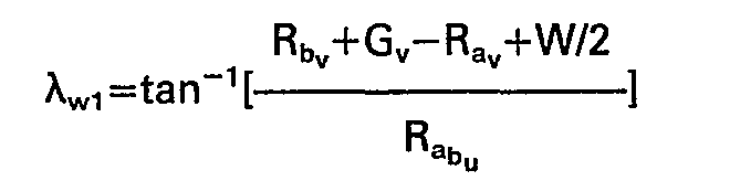
- The elevation and traverse coordinate angles to be displayed for the pair of pips simulating a bullet are, respectively


- Zp=gun-to-sight parallax; 0≤ZP≤6 meters
- W=target wing span
- These expressions for λv, λw1, and λw2 can be simplified by replacing certain terms in their derivations with suitable approximations. In particular, the second and third terms on the right of equations (15) can be neglected for most all air-to-air gunnery situations of interest. Maximum error resulting from this approximation is estimated by evaluating the term ωvRaw.


- ωv=0.25 rad/sec
- Va=270 meters/sec.
- Tf (time of flight of bullet)=1 sec.
- a=0.2 rad,

- This is a negligible error in range. A similar approximation in equation (7) is inappropriate because the corresponding range error would be almost an order of magnitude larger than in (23).
- A potentially significant source of error, however, can result from the finite rate of incremental digital computation. An estimate of this error can be obtained from analysis of equations (8) and (9). Elevation angular error s resulting from digital integration during each incremental computation time interval At is approximately

- Total elevation angular error at a particular time of flight is


- Although this error is small, it is not entirely negligible. Because it is small, however, it can be corrected by simply adding the estimated error (31) to the final computation of elevation angle.
- Traverse error is estimated from equation (8).

- It is sufficiently accurate for error analysis to assume coordinated flight, i.e.,

- If rudder pedals are used to any significant degree to generate side slip, the analysis of the second term (





- Error due to first order integration is


-


- This is not a negligible error, particularly since it is a lateral error. Equation (42) is therefore an appropriate correction to be added to the traverse bullet angle. Traverse angles (22) and (23) may be approximated by the argument of the arc tan function with sufficient accuracy.

- Table 1 lists the error due to omitting the third order term


- The third order term is apparently necessary for elevation angles but not for traverse angles.
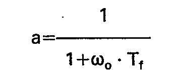
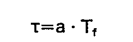
- The foregoing equations for deriving the angular display coordinates λv,


- 1. Aero drag

- 2. Initial bullet velocity as observed in aircraft (u, v, w) coordinates



- 3. Bullet range relative to firing point



- 4. Aircraft range relative to firing point


- 5. Gravity drop


- 6. Bullet range relative to aircraft


- 7. Sight angles


- Although the above-discussed equations enable the gunnery firing and evaluation system and method to provide meaningful results in practice of air gunnery, significant additional capability is available when the aircraft's radar is employed to effect range lock-on. With this capability, it is possible to display the rounds or pairs of pips at target range directly, although the instantaneous positions of the pairs of pips would still be displayed.
- Some advantages of this approach are:
- 1. A direct display of bullet miss distance greatly simplifies data reduction.
- 2. The pilot is provided an immediate in-flight assessment of firing effectiveness.
- 3. A more accurate measure of miss distance at long range is available.
- 4. Redundancy in the measurement of bullet miss distance provides additional accuracy or greater assurance that some useful information will always be obtained.
- The angular position of the bullet at target range is displayed in the form of a six milliradian circle (dispersion) at the time that bullet range is equal to target range. A somewhat simpler, and sufficiently accurate approach is to compare the u axis component of bullet position with the u axis component of target range, i.e.,

- RT=target range from radar
- λtv=Radar elevation gimbal angle (relative to ADL)
- AtW=Radar traverse gimbal angle.
- Bullet angle would be displaced at the first iteration following inequality (44).
- Because of the high angular rates characteristic of air-to-air gunnery, some interpolation between computer iterations will generally be required.
- For an angular rate of 200 mr/sec, for example, the mentioned computer (iteration time interval At of 0.02 sec. produces a 4 mr step between successive bullet angles. This is not a negligible error, although it is small.
- Let

- The appropriate corrections to bullet range components before display are therefore

-


-


- Because of the significantly lower yaw rates, interpolartion for Ray does not appear to be justifiable.
- The elevation and traverse angular coordinates would then be calculated according to the equations summarized in (7) above.
- Fig. 5 shows in more detail the
computer 30 of Fig. 3. Thecomputer 30 comprises acentral processor unit 102 interconnected with atiming circuit 104 and amemory 106. Thecentral processor unit 102 receives the outputs from air data generator 34,inertial data generator 36 andtrigger subsystem 38 overbus 64 through input/output control 108. Similarly, theCPU 102 passes information frommemory 106 tobus 66 and tosymbol generator 28 through the input/output control 108. This information comprises the angular coordinates for the pairs of bullet trajectory indicia or pips displayed on the combiningglass 22 by thesighting display unit 24. A suitable central processor unit is the MCP701A digital display processor manufactured by General Electric Co. - In the preferred embodiment, the angular coordinates of the pairs of pips are generated by
central processor unit 102 by means of the above-discussed equations. In order to perform these calculations and generate the angular coordinates, thecentral processor 102 is programmed to perform the necessary operations. Figs. 6a and 6b show the program for accomplishing this task. - Fig. 7 shows the data tables resident in
memory 106 for storing the data necessary to perform the calculations. - Fig. 8 shows the display tables also resident in
memory 106 for storing the angular coordinate of the pairs of pips. - The following is a list of mnemonics for the data quantities used in calculating the angular coordinates:
- XC - the C register in the MCP701A computer;
- XA - the A register in the MCP701A computer;
- XB - the B register in the MCP701A computer;
- NBUT - number of simulated bullets displayable at the same time to represent a bullet stream (10 maximum);
- KBUT - used as a pointer, initially equals NBUT and is decremented N times;
- ITMAX - constant equal to 1 +(the total time of flight)/(iteration rate);
- TFF - time of flight for a simulated bullet;
- PG35 - starting address of
page 3 scratch pad memory; - DEND - address of last location used in display table;
- DRANG - calculated range from firing aircraft to simulated bullet;
- DMIN - constant set to check the minimum range;
- BIPAS - represents the routine to bypass displaying a simulated bullet if;
- 1. T(K)=0;
- 2. DRANG<DMIN; or
- 3. bullet is out of the field of view of HUD;
- TRFLG - a discrete word equal to one when the trigger is squeezed to fire a simulated bullet; this task.
- TRFLG1 - a discrete word set equal to one when the trigger is squeezed to fire a simulated bullet; and BSC - counter utilized to indicate when to initiate a new bullet.
- The tables in Fig. 7 store data concerning and describing the condition of each simulated bullet. In this example, each table has ten entries and, thus, the system is capable of simultaneously displaying ten simulated bullets in the form of ten pairs of bullet trajectory indicia, i.e., ten pairs of pips. The information stored in the tables comprises:
- T(K) - the current time of flight for a simulated bullet;
- DRANG - the range vector for a simulated bullet;
- DVBV - Incremental bullet velocity along the v axis;
- DVBV1 - DVBV from previous iteration;
- DVBW - Incremental bullet velocity along the w axis;
- RVDOT - v axis range rate of the bullet;
- RVDOT1 - RVDOT from previous iteration;
- RWDOT - w axis range rate of the bullet;
- RWDOT1 - RWDOT from previous iteration;
- AB - the current acceleration of the bullet;
- VB - the current velocity of the bullet;
- DVB - Bullet speed minus aircraft speed;
- VBW - w axis bullet velocity;
- RVV - v axis bullet range;
- RVV1 - RW from previous iteration;
- RWW - w axis bullet range;
- The quantities RVV, RW1, and RWW are both double precision, meaning that two words of storage are provided for each of these quantities.
- Referring now to Fig. 6a, the operation of the firing evaluation and display system is initiated by setting the A register and the B register to PG35. K is set to one and KBUT is set to NBUT. The next step is to fetch T(K) which in this instance would be T(1 This quantity is checked for zero and, if it is zero, then that entry in the bullet table is not active and no update of a bullet position is required for that entry. In such case, KBUT is decremented by one and checked to see if it is zero. If KBUT is zero then all the entries in the bullet table have been processed and processing continues to update any remaining display angular coordinates.
- If, however, the content of T(K) is not equal to zero, indicating that this entry in the bullet table reflects an active simulated bullet, then the quantity T(K) is set to the quantity T(K)-1. The time of flight is computed as

- After computing the time of flight, TFF, the new bullet position for bullet K is calculated according to the foregoing equations and the results are stored in the Kth entry of the bullet tables shown in Fig. 7. Next, the pointer into the number of bullets processed, KBUT, is decremented by one and checked to see if it is zero. If it is not, the A register is incremented by one, the B register is incremented by two and K is incremented by one. The next entry in the bullet table is processed in the above-described manner and the same procedures are iteratively performed until all entries in the bullet table have been accessed and new bullet positions calculated and stored for each active entry.
- Once this has been accomplished, the A register and B register are reset to PG35, the C register is set to DEND, K is reset to one and KBUT is set to NBUT. The processing continues to update the angular coordinates for each bullet trajectory indicia or pair of bullet pips stored in the bullet display table of Fig. 8.
- This is accomplished by first fetching the first entry in the bullet table T(K) [K= in this instance]. If T(K) is equal to zero, then this bullet entry in the bullet table is inactive and no further processing is required. Thus, the computer operation passes to BIPAS and preparations are made to examine the next entry in the bullet table. If, however, the T(K) entry is not equal to zero then DRANG for that bullet entry in the bullet table is checked against the minimum display range DMIN. If DRANG is less than DMIN, then further processing for that entry in the bullet table is bypassed. If not, the x and y positions for each pip of a pair of pips representing the simulated bullet is compared to maximum display parameters to insure that the
computer 30 does not generate angular display coordinates which are outside of the display range ofdisplay unit 24. If such is the case, further processing for that entry in the bullet table is bypassed. If, however, the x and y coordinates are within the display limits, the angular display coordinates stored in the display table shown in Fig. 8 corresponding to this bullet position in the bullet table of Fig. 7 are updated with the newly calculated bullet position for that particular bullet entry. - The display table of Fig. 8 utilizes six words of storage for each bullet. These six words store, in order, POSX, POSY, corresponding to λv and λw1, respectively. A JM5 instruction meaning to jump five words ahead in processing, POSX, POSY, corresponding to Àv and A,,2, respectively, and another JM5 instruction.
- The bullet display table shown in Fig. 8 reflects two active bullet positions, i.e.,
bullet 1 andbullet 2 and eight inactive bullet positions 3-10. In an inactive bullet position, the first word of storage is a JMP6 instruction which results in bypassing all processing for that entry in the bullet display table. - Once the entry in the bullet display table has been updated with new angular coordinates reflecting the newly determined bullet position, the entry T(K) is checked to see if it is equal to one. If it is, that entry in the bullet table is made inactive by setting T(K) equal to zero. This is done because the time of flight for the simulated bullet corresponding to that entry in a bullet table is equal to the maximum time of flight within the system and, thus, the pair of pips for that particular bullet entry will not longer be displayed.
- As can be seen from Fig. 6a, the operations following (1) the BIPAS determination, (2) a determination that T(K) is equal to one, and (3) the setting of T(K) to zero are all the same. These operations include incrementing the A register by one, incrementing the B register by two, incrementing the C register by six, incrementing K by one and decrementing KBUT by one. If KBUT is not equal to zero then the next entry in the bullet table is processed in the foregoing manner in order to update its corresponding entry in the bullet display table.
- If all entries in the bullet table have been processed, i.e., KBUT equals zero, then the END routine is loaded in the display table and the symbol generator is permitted to transfer the angular coordinates of each pair of pips to the display unit for display on
sighting panel 22. The manner in which the display of the pips is accomplished in response to the angular display coordinates is well-known and need not be further discussed. - The processing operations set forth in Fig. 6b are performed in response to the firing of another simulated bullet by the gun operator or pilot. First the trigger flag, TRFLG is checked to see if it equals one. If it does not, then no new simulated bullet has been fired and processing returns to the bullet table updating routines set forth in Fig. 6a. If TRFLG is equal to one then another trigger flag TRFLG1 is also checked to see if it equals one. If it does, the bullet counter BSC is decremented by one and checked to see if it equals zero. If it is not equal to zero then a sufficient time has not passed since the previous bullet has been entered into the system and processing returns to the bullet position update routines in Fig. 6a.
- If, however, BSC is equal to zero, then BSC is reset, i.e., set to six in this instance, and a new entry is placed in the bullet tables shown in Fig. 7.
- The reason that a new bullet entry may not be placed in the bullet table immediately upon the depression of the trigger by the gun operator, is that the system is set up to accommodate a finite number of bullets, in this case ten, and due to the speed of processing by the CPU, the continuous depression of the trigger could overflow the number of entries in the bullet table very rapidly. Since the system is adapted to display ten bullets for a maximum time period of one second, then a new bullet is entered into the system at tenth second intervals.
- The entry of a new, simulated bullet into the system is accomplished by scanning the bullet table for zero entries in the T(K) positions. If a zero entry is found, ITMAX is loaded into the T(K) storage position for the detected position in the bullettable. Also, intialization of certain variables is performed at this time, and the instantaneous values of the air data sensors and inertial data sensors are stored in appropriate form in that entry of the bullet table. After these initialization steps are performed, processing returns to the bullet updating routines of Fig. 6a.
- In operation, a pilot sitting at B (Fig. 3) sights a target aircraft in his field of view 11. The pilot operates the trigger subsystem by actuating the aircraft selector and the trigger for the guns of the aircraft. The aircraft selector generates an aircraft selector pulse AS identifying the type of target aircraft and the trigger subsystem generates trigger pulses T for each depression or the continual depression of the trigger. These signals are provided to the analog-to-digital converter 32.
- Meanwhile, the air data generator 34 is supplying instantaneous values for the velocity of the aircraft, Va, the gun angle of attack, Qg, and relative air density p. These signals are similarly encoded by the analog-to-digital converter 32. The
inertial data generator 36 is also supplying instantaneous values for the aircraft lift acceleration Aw, roll rate p, pitch rate q, and yaw rate r. Again, these signals are encoded by the analog-to-digital converter 32 and, with the other inputs, are supplied tocomputer 30. - The
computer 30 creates an entry in a bullet table stored in its memory for each simulated bullet fired by the pilot. All necessary information for computing and displaying the trajectory of the simulated bullet is stored in its corresponding entry in the bullet table. From this data, the computer computes a range vector and velocity vector for each simulated bullet. Angular display coordinates are generated from the range vector and velocity vector such that a pair of bullet trajectory indicia or visible pips can be displayed in a manner that represents the trajectory of the simulated bullet over a particular time span. The equations necessary for computing the range vector and velocity vector as well as the angular display coordinates have been previously set forth. - The angular display coordinates for the pips are stored in the bullet display table. Periodically, the computer transfers the contents of the bullet display table to the
symbol generator 28 which controls thedisplay unit 24 in a manner that will project the bullet trajectory indicia or pips corresponding to each simulated bullet on combiningglass 22. This superimposes the pips on the field of view of the pilot so that the relative position of the pips and the target aircraft can be observed. Optionally, acamera 72 is coupled to thedisplay unit 24 bycontrol lines 74 such that the camera can record on videotape the superimposed image of the pips and target much as they are actually seen by the pilot. - The computer continually updates the trajectory for each pair of display pips so that the pips are made to appear to approach the target much as actual bullets would approach the target. This is accomplished by decreasing the distance between the pair of pips while continually updating the display position of the pips. The initial separation between the pips is computed by
computer 30 in accordance with the target identification signal AS generated by the trigger subsystem. This separation is a function of some dimension of the identified target, for example, aircraft wingspan. The convergence of the pips is computed to represent the apparent decrease in the selected dimension of the target with increasing distance. - A hit of the target aircraft by the simulated bullet occurs when the pips are seen to be superimposed upon the target and separated from each other by the same distance as the selected dimension of the target. Again, as an example, if the selected dimension is the wingspan of an aircraft then the separation between the pips would have to be equal to the wingspan of the target aircraft as it appears to the pilot when the pips-are directly superimposed on the target. This corresponds to the intersection of the plane of the target by the pips representing the simulated bullet.
- As an alternate embodiment, a
radar unit 31 can be employed to supply the actual range to the target, Rt, by radar lock-on. Given this actual target range, the computer can be programmed to compute the point in time that the simulated bullet would arrive at that range. When this occurs, the computer generates a dispersion pattern or other type of visible signal indicating that the pips have arrived at the range of the target. If the pips are directly superimposed over the target at the time of the visible signal, then it can be assumed that a bullet simulated by the pips would have hit the target aircraft. Thevideo camera 72 records the image of the target, the continually changing position of the pips and also the visible signal generated when the pips reach the target range. - It will be understood that the use of the videotape with or without radar lock-on enables the evaluation of the firing technique and accuracy of the pilot. It enables pilots to study gunnery techniques while using actual aircraft as targets in simulated combat situations but avoids the previously mentioned drawbacks of using drones and towed targets.
- It will be apparent, to those skilled in the art, that modifications and variations can be made in the exemplary system disclosed herein. For example, a system wherein more than ten bullets could be simultaneously displayed may be employed. Also, more than two pips could be used to represent each simulated bullet.
*Read R(T,) typically as: "range as a function of time of flight of the bullet," and R'(Tf) as: "the updated value of R(Tf)".
Claims (5)



Applications Claiming Priority (2)
| Application Number | Priority Date | Filing Date | Title |
|---|---|---|---|
| US105606 | 1979-12-20 | ||
| US06/105,606 US4308015A (en) | 1979-12-20 | 1979-12-20 | System and method for aircraft gunnery training and accuracy evaluation |
Publications (3)
| Publication Number | Publication Date |
|---|---|
| EP0042004A1 EP0042004A1 (en) | 1981-12-23 |
| EP0042004A4 EP0042004A4 (en) | 1982-04-29 |
| EP0042004B1 true EP0042004B1 (en) | 1985-09-11 |
Family
ID=22306789
Family Applications (1)
| Application Number | Title | Priority Date | Filing Date |
|---|---|---|---|
| EP81900248A Expired EP0042004B1 (en) | 1979-12-20 | 1980-12-17 | Gunnery simulation system |
Country Status (8)
| Country | Link |
|---|---|
| US (1) | US4308015A (en) |
| EP (1) | EP0042004B1 (en) |
| JP (2) | JPS56501538A (en) |
| AU (1) | AU532500B2 (en) |
| DE (1) | DE3071066D1 (en) |
| IL (1) | IL61732A (en) |
| IT (1) | IT1193570B (en) |
| WO (1) | WO1981001875A1 (en) |
Families Citing this family (13)
| Publication number | Priority date | Publication date | Assignee | Title |
|---|---|---|---|---|
| US4698489A (en) * | 1982-09-30 | 1987-10-06 | General Electric Company | Aircraft automatic boresight correction |
| FR2536921A1 (en) * | 1982-11-30 | 1984-06-01 | Thomson Csf | LOW WASTE VOLTAGE REGULATOR |
| FR2536847B1 (en) * | 1982-11-30 | 1986-10-17 | Thomson Csf | SMALL CALIBER SHOOTING TRAINING SIMULATOR ON SIMULATED TARGETS |
| US4661987A (en) * | 1985-06-03 | 1987-04-28 | The United States Of America As Represented By The Secretary Of The Navy | Video processor |
| US5228854A (en) * | 1992-07-21 | 1993-07-20 | Teledyne, Inc. | Combat training system and method |
| JP3503982B2 (en) * | 1994-03-18 | 2004-03-08 | 富士通株式会社 | Viewpoint setting device |
| JP3442965B2 (en) * | 1997-04-25 | 2003-09-02 | 任天堂株式会社 | Video game system and storage medium for video game |
| US6875019B2 (en) * | 2002-02-11 | 2005-04-05 | United Defense, Lp | Naval virtual target range system |
| AUPS230802A0 (en) * | 2002-05-14 | 2002-06-13 | Roberts, David Grant | Aircraft based visual aid |
| EP1643206A1 (en) * | 2004-10-02 | 2006-04-05 | Saab Ab | Simulation system, method and computer program |
| DE102005041704A1 (en) * | 2005-09-02 | 2007-03-15 | Oerlikon Contraves Ag | Method for optimizing a fire triggering of a weapon or a gun |
| WO2008115216A2 (en) * | 2006-12-01 | 2008-09-25 | Aai Corporation | Apparatus, method and computer program product for weapon flyout modeling and target damage assesment |
| CN118192303B (en) * | 2024-05-16 | 2024-08-13 | 成都流体动力创新中心 | Semi-physical simulation method and system |
Family Cites Families (12)
| Publication number | Priority date | Publication date | Assignee | Title |
|---|---|---|---|---|
| US2467831A (en) * | 1942-09-26 | 1949-04-19 | Gen Electric | Sighting mechanism |
| US3024536A (en) * | 1954-08-11 | 1962-03-13 | Mathema Corp Reg Trust | Ordnance sight for mobile targets |
| US2843028A (en) * | 1955-03-11 | 1958-07-15 | William C Ward | Miss-distance indicator |
| US2979711A (en) * | 1956-06-29 | 1961-04-11 | North American Aviation Inc | Fire control system |
| US2957384A (en) * | 1956-11-27 | 1960-10-25 | Gen Motors Corp | Optical sighting device |
| US2957245A (en) * | 1957-05-29 | 1960-10-25 | Creighton B Kimble | Electronic reticle generator |
| US3137769A (en) * | 1961-01-24 | 1964-06-16 | Barnes Eng Co | Reflex sighting |
| DE1951622C3 (en) * | 1969-10-14 | 1974-03-28 | Honeywell Gmbh, 6000 Frankfurt | Arrangement for the simulated display of firing trajectories |
| SE340061B (en) * | 1970-03-06 | 1971-11-01 | Bofors Ab | |
| US3716696A (en) * | 1970-09-04 | 1973-02-13 | Honeywell Inc | Projectile stream display apparatus |
| US3671100A (en) * | 1970-10-23 | 1972-06-20 | Perkins Elmer Corp The | System for integrating gunsight reticle image and image received by a camera |
| DE2746534C2 (en) * | 1977-10-17 | 1982-07-29 | Honeywell Gmbh, 6000 Frankfurt | Method for simulating a moving target |
-
1979
- 1979-12-20 US US06/105,606 patent/US4308015A/en not_active Expired - Lifetime
-
1980
- 1980-12-17 WO PCT/US1980/001681 patent/WO1981001875A1/en not_active Ceased
- 1980-12-17 DE DE8181900248T patent/DE3071066D1/en not_active Expired
- 1980-12-17 IL IL61732A patent/IL61732A/en not_active IP Right Cessation
- 1980-12-17 JP JP81500429A patent/JPS56501538A/ja active Pending
- 1980-12-17 JP JP56500429A patent/JPH06100439B2/en not_active Expired - Lifetime
- 1980-12-17 EP EP81900248A patent/EP0042004B1/en not_active Expired
- 1980-12-19 IT IT26794/80A patent/IT1193570B/en active
- 1980-12-19 AU AU65560/80A patent/AU532500B2/en not_active Expired
Also Published As
| Publication number | Publication date |
|---|---|
| WO1981001875A1 (en) | 1981-07-09 |
| DE3071066D1 (en) | 1985-10-17 |
| EP0042004A1 (en) | 1981-12-23 |
| IT1193570B (en) | 1988-07-08 |
| JPS55501199A (en) | 1980-12-25 |
| EP0042004A4 (en) | 1982-04-29 |
| JPS56501538A (en) | 1981-10-22 |
| JPH06100439B2 (en) | 1994-12-12 |
| IT8026794A0 (en) | 1980-12-19 |
| IL61732A (en) | 1985-01-31 |
| AU6556080A (en) | 1981-06-25 |
| AU532500B2 (en) | 1983-09-29 |
| US4308015A (en) | 1981-12-29 |
Similar Documents
| Publication | Publication Date | Title |
|---|---|---|
| US3845276A (en) | Laser-sight and computer for anti-aircraft gun fire control system | |
| US4698489A (en) | Aircraft automatic boresight correction | |
| EP0042004B1 (en) | Gunnery simulation system | |
| US5794889A (en) | Fire retardant delivery system | |
| US2992423A (en) | Rocket launch control systems | |
| US3699310A (en) | Angular rate bombing system | |
| KR101560295B1 (en) | Apparatus for simulation target training | |
| US3716696A (en) | Projectile stream display apparatus | |
| US3995144A (en) | Banked bombing system | |
| RU2170907C1 (en) | Method for aiming in attack of high-speed targets by fighter in flat trajectory and device for its realization | |
| US3206143A (en) | Controller for guiding a missile carrier on the location curve of ballistic firing positions | |
| KR850000014B1 (en) | Shooting system | |
| RU2707325C1 (en) | Aiming method when gun firing at maneuvering air target | |
| US3075188A (en) | Stable optical tracking fire control system | |
| Gilbert et al. | Snap-Shoot Gunsight for Fixed-Gun Fighter Aircraft | |
| Hodson | A projectile subsystem in a flight simulation system | |
| Wiles | Air-to-air gunnery systems test and evaluation | |
| BURESH et al. | Air-to-air combat development of the AH-64A Apache | |
| Elwell et al. | A Computer Model for the Evaluation of Helicopter Fire Control Systems | |
| RU2172463C2 (en) | Method and system for combat vehicle fire a target | |
| Jupin | The ballistics processor of a multiple processor airborne tactical system | |
| Frederick | Electrical Fire Control: The Development and Function of a New Antiaircraft Director | |
| COLBURN | Qualitative armament subsystem assessment | |
| Guercio et al. | LASER GUIDED BOMBS AND CONVERTIBLE DESIGNATION POD INTEGRATION ON ITALIAN TORNADO-IDS | |
| Smith | Air Combat Accuracy Methodology Dynamic Air-to-Air Model |
Legal Events
| Date | Code | Title | Description |
|---|---|---|---|
| PUAI | Public reference made under article 153(3) epc to a published international application that has entered the european phase |
Free format text: ORIGINAL CODE: 0009012 |
|
| AK | Designated contracting states |
Designated state(s): DE FR GB NL SE |
|
| 17P | Request for examination filed |
Effective date: 19811214 |
|
| GRAA | (expected) grant |
Free format text: ORIGINAL CODE: 0009210 |
|
| AK | Designated contracting states |
Designated state(s): DE FR GB NL SE |
|
| REF | Corresponds to: |
Ref document number: 3071066 Country of ref document: DE Date of ref document: 19851017 |
|
| ET | Fr: translation filed | ||
| PLBE | No opposition filed within time limit |
Free format text: ORIGINAL CODE: 0009261 |
|
| STAA | Information on the status of an ep patent application or granted ep patent |
Free format text: STATUS: NO OPPOSITION FILED WITHIN TIME LIMIT |
|
| PG25 | Lapsed in a contracting state [announced via postgrant information from national office to epo] |
Ref country code: DE Effective date: 19860902 |
|
| 26N | No opposition filed | ||
| EAL | Se: european patent in force in sweden |
Ref document number: 81900248.6 |
|
| PGFP | Annual fee paid to national office [announced via postgrant information from national office to epo] |
Ref country code: FR Payment date: 20000119 Year of fee payment: 20 |
|
| PGFP | Annual fee paid to national office [announced via postgrant information from national office to epo] |
Ref country code: SE Payment date: 20000120 Year of fee payment: 20 Ref country code: GB Payment date: 20000120 Year of fee payment: 20 |
|
| PGFP | Annual fee paid to national office [announced via postgrant information from national office to epo] |
Ref country code: NL Payment date: 20000125 Year of fee payment: 20 |
|
| PG25 | Lapsed in a contracting state [announced via postgrant information from national office to epo] |
Ref country code: GB Free format text: LAPSE BECAUSE OF EXPIRATION OF PROTECTION Effective date: 20001216 |
|
| PG25 | Lapsed in a contracting state [announced via postgrant information from national office to epo] |
Ref country code: NL Free format text: LAPSE BECAUSE OF EXPIRATION OF PROTECTION Effective date: 20001217 |
|
| PG25 | Lapsed in a contracting state [announced via postgrant information from national office to epo] |
Ref country code: SE Free format text: THE PATENT HAS BEEN ANNULLED BY A DECISION OF A NATIONAL AUTHORITY Effective date: 20001230 |
|
| REG | Reference to a national code |
Ref country code: GB Ref legal event code: PE20 Effective date: 20001216 |
|
| NLV7 | Nl: ceased due to reaching the maximum lifetime of a patent |
Effective date: 20001217 |
|
| EUG | Se: european patent has lapsed |
Ref document number: 81900248.6 |