EP0041899B1 - Eléments de bombage de plaques en un matériau à l'état plastique, application de ces éléments au bombage et à la trempe desdites plaques et dispositifs équipés de tels éléments - Google Patents
Eléments de bombage de plaques en un matériau à l'état plastique, application de ces éléments au bombage et à la trempe desdites plaques et dispositifs équipés de tels éléments Download PDFInfo
- Publication number
- EP0041899B1 EP0041899B1 EP81400909A EP81400909A EP0041899B1 EP 0041899 B1 EP0041899 B1 EP 0041899B1 EP 81400909 A EP81400909 A EP 81400909A EP 81400909 A EP81400909 A EP 81400909A EP 0041899 B1 EP0041899 B1 EP 0041899B1
- Authority
- EP
- European Patent Office
- Prior art keywords
- plates
- tempering
- curving
- boxes
- bending
- Prior art date
- Legal status (The legal status is an assumption and is not a legal conclusion. Google has not performed a legal analysis and makes no representation as to the accuracy of the status listed.)
- Expired
Links
- 238000005496 tempering Methods 0.000 title claims description 23
- 239000004033 plastic Substances 0.000 title claims description 17
- 238000005452 bending Methods 0.000 title description 64
- 239000011521 glass Substances 0.000 claims description 37
- 239000000463 material Substances 0.000 claims description 10
- 238000007664 blowing Methods 0.000 claims description 8
- 230000000295 complement effect Effects 0.000 claims description 2
- 238000010791 quenching Methods 0.000 description 7
- 230000000171 quenching effect Effects 0.000 description 7
- 230000008859 change Effects 0.000 description 4
- 230000004048 modification Effects 0.000 description 4
- 238000012986 modification Methods 0.000 description 4
- 230000003287 optical effect Effects 0.000 description 4
- 238000004519 manufacturing process Methods 0.000 description 3
- 230000000750 progressive effect Effects 0.000 description 3
- 238000001816 cooling Methods 0.000 description 2
- 238000010586 diagram Methods 0.000 description 2
- 238000000034 method Methods 0.000 description 2
- 238000003303 reheating Methods 0.000 description 2
- 241001080024 Telles Species 0.000 description 1
- 241001639412 Verres Species 0.000 description 1
- 230000007547 defect Effects 0.000 description 1
- 238000006073 displacement reaction Methods 0.000 description 1
- 238000010438 heat treatment Methods 0.000 description 1
- 238000009434 installation Methods 0.000 description 1
- 239000002985 plastic film Substances 0.000 description 1
- 238000007639 printing Methods 0.000 description 1
- 230000008569 process Effects 0.000 description 1
- 230000000284 resting effect Effects 0.000 description 1
- 238000007789 sealing Methods 0.000 description 1
Images

Classifications
-
- C—CHEMISTRY; METALLURGY
- C03—GLASS; MINERAL OR SLAG WOOL
- C03B—MANUFACTURE, SHAPING, OR SUPPLEMENTARY PROCESSES
- C03B27/00—Tempering or quenching glass products
- C03B27/04—Tempering or quenching glass products using gas
- C03B27/0404—Nozzles, blow heads, blowing units or their arrangements, specially adapted for flat or bent glass sheets
-
- C—CHEMISTRY; METALLURGY
- C03—GLASS; MINERAL OR SLAG WOOL
- C03B—MANUFACTURE, SHAPING, OR SUPPLEMENTARY PROCESSES
- C03B23/00—Re-forming shaped glass
- C03B23/02—Re-forming glass sheets
- C03B23/023—Re-forming glass sheets by bending
- C03B23/03—Re-forming glass sheets by bending by press-bending between shaping moulds
- C03B23/031—Re-forming glass sheets by bending by press-bending between shaping moulds the glass sheets being in a vertical position
-
- C—CHEMISTRY; METALLURGY
- C03—GLASS; MINERAL OR SLAG WOOL
- C03B—MANUFACTURE, SHAPING, OR SUPPLEMENTARY PROCESSES
- C03B23/00—Re-forming shaped glass
- C03B23/02—Re-forming glass sheets
- C03B23/023—Re-forming glass sheets by bending
- C03B23/035—Re-forming glass sheets by bending using a gas cushion or by changing gas pressure, e.g. by applying vacuum or blowing for supporting the glass while bending
-
- C—CHEMISTRY; METALLURGY
- C03—GLASS; MINERAL OR SLAG WOOL
- C03B—MANUFACTURE, SHAPING, OR SUPPLEMENTARY PROCESSES
- C03B27/00—Tempering or quenching glass products
- C03B27/04—Tempering or quenching glass products using gas
- C03B27/0422—Tempering or quenching glass products using gas for flat or bent glass sheets starting in an horizontal position and ending in a non-horizontal position
- C03B27/0426—Tempering or quenching glass products using gas for flat or bent glass sheets starting in an horizontal position and ending in a non-horizontal position for bent glass sheets
- C03B27/0431—Tempering or quenching glass products using gas for flat or bent glass sheets starting in an horizontal position and ending in a non-horizontal position for bent glass sheets the quench unit being adapted to the bend of the sheet
-
- C—CHEMISTRY; METALLURGY
- C03—GLASS; MINERAL OR SLAG WOOL
- C03B—MANUFACTURE, SHAPING, OR SUPPLEMENTARY PROCESSES
- C03B27/00—Tempering or quenching glass products
- C03B27/04—Tempering or quenching glass products using gas
- C03B27/044—Tempering or quenching glass products using gas for flat or bent glass sheets being in a horizontal position
- C03B27/048—Tempering or quenching glass products using gas for flat or bent glass sheets being in a horizontal position on a gas cushion
-
- C—CHEMISTRY; METALLURGY
- C03—GLASS; MINERAL OR SLAG WOOL
- C03B—MANUFACTURE, SHAPING, OR SUPPLEMENTARY PROCESSES
- C03B27/00—Tempering or quenching glass products
- C03B27/04—Tempering or quenching glass products using gas
- C03B27/052—Tempering or quenching glass products using gas for flat or bent glass sheets being in a vertical position
Definitions
- the invention relates to the bending of plates of a material in the plastic state, in particular of glass sheets at a temperature equal at least to the softening temperature of this glass. It relates more particularly to elements which can be used as a form of bending of these plates and to devices equipped with at least one such element. It also relates to the application of these elements to bending and / or tempering said sheets.
- French patent FR 2 312 463 it is also known to carry out the bending in a progressive manner by constituting with the same curved rods a conformation bed with progressive convexity, the first rod of the bed being practically lying in the plane of the rollers which bring the sheet of glass at the bending station, the last rod having the straightening which gives the desired bending and the intermediate rods being also fixed, but wedged in positions all the more straightened as they are closer to the last rod of the bed conformation.
- the glass sheet bulges as it progresses, without it being necessary to modify the position of the rods, adjusted once and for all for manufacturing at a given radius of curvature.
- the present invention provides a glass bending device combining the advantages of the two known systems, recalled above, namely leading to a glass of good optical quality, while easily lending itself to a change in the radius of curvature to be printed on the plates. in the plastic state to be treated.
- the subject of the invention is an element which can be used as a form for bending or tempering plates made of a material in a plastic state, this element intended to be placed opposite said plates, transversely to their direction of advance. , being such that it has a plurality of profiles in a plane perpendicular to the direction of advancement of the plates and that it comprises means for adjusting its position in this plane, these means acting so as to preserve the top of the shape thus produced at a fixed point of said plane.
- This plurality of profiles is obtained thanks to a radius of curvature which varies continuously, in particular thanks to a spiral profile, in particular a logarithmic spiral.
- the element which can be used as a form for bending or quenching consists of a box equipped on its face facing the plates, with means for blowing a gas.
- the element which can be used as a form for bending or quenching consists of a curved rod comprising a sheath driven in rotation around it.
- the invention also relates to a device for bending or tempering plates made of a material in a plastic state, in particular glass sheets, such that it comprises one or more shapes for bending or tempering, including one at least has at least one element, box or curved rod, with a previously defined profile, as well as means for driving the plates or sheets if necessary.
- these boxes can all see the same profile, and be juxtaposed, possibly with an offset in their tilting, depending on the radius of curvature that it is desired to print on the treated plastic sheet. remains constant or gradually varies as it progresses longitudinally.
- the element which can be used as a form for bending or quenching is a curved rod of the same type as the rods of the prior art, surrounded by a tubular sheath driven in rotation, but having a variable profile identical to that of the boxes and being tiltable in a plane transverse to the direction of advancement of the glass sheets.
- rods of the second embodiment there will be arranged between the boxes of the first embodiment, or instead of some of them, rods of the second embodiment.
- any means known per se can be used as the means for driving the sheets to be treated, in particular laterally arranged cleat chains.
- the retaining cleats will preferably be adjustable, so that their position can be adapted to the shape of the plates. For each series of plates, the cleats will be adjusted once and for all and the cleats and plates will appear with the same frequency.
- the entire bending device will be inclined laterally on the side of the lug chain.
- the box or boxes of the bending device according to the invention will advantageously have, in a plane perpendicular to the direction of advance of the sheets to be treated, a spiral profile, in particular a logarithmic spiral profile.
- a short arc of such a curve has a radius of curvature which varies sufficiently quickly and gradually and, on the other hand, a box having such a profile lends itself to an easy and rapid change radius of curvature.
- the invention is naturally not limited to boxes having this profile, but these constitute a preferred form of implementation.
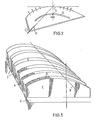
- the bending device shown in Figure 1 comprises a plurality of boxes 1, supported by the same frame 2. These boxes are intended to be arranged perpendicular to the path 3 of a plate made of a material in the plastic state, glass by example, and below this plate, studs or blowing nozzles being provided on the upper surface 5 of said boxes, for directing a gas, air for example, towards the lower face of this plate, which thus rests on a gas cushion.
- the upper face 5 of the boxes 1 has a curved profile, the radius of curvature of which varies continuously from one end to the other of a box, transverse to the direction 3. It is thus possible, by judiciously arranging a box in a plane transverse to this direction 3 of advancement of the plates which exit from the reheating furnace, bringing below the passage of the dish to dish the part of the upper face of this box which has the radius desired curvature.
- the spacing of the boxes may however give rise to undulations in the glass plate, as is the case with the devices with rotary rods of the prior art.
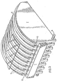
- the boxes can be placed together, as shown in FIG. 2, and their profile can be varied regularly, according to the direction of advancement F of the treated plates, so that they are equivalent to a single continuous box when they are juxtaposed.
- curved rods 9 of the prior art coated with a tubular sheath driven in rotation by one of its ends 10 , these curved rods 9 then having the same profile as the boxes.
- the curved rods 9 are carried by a frame 11 secured to the boxes 7 and it is the set of rods 9 and boxes 7 which are moved in a transverse plane, for example by tilting, when it is desired to vary the bending radius.
- the rods 9 protrude slightly above the upper face of the boxes 7 and they contribute to driving the plates of material in the plastic state to be treated, at the same time as the bending of these plates.
- These rods 9 can also be mounted in an individual frame.
- the rods 9 are not in a strictly vertical plane, but are slightly inclined in the direction of advancement of the treated plates, so as to self-center them along the bending axis, while only printing them very low rotation.
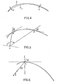
- the upper surface of the boxes and / or rods will advantageously have the shape of a spiral, in particular a logarithmic spiral, because this shape lends itself to an adjustment in very simple position for the boxes. and therefore an easy modification of the radius of curvature.
- the tangent to the vertex C of the bending shape formed by the box and / or the rod remain fixed, when the box or the rod is moved in a plane perpendicular to the direction of advancement of the plates to be treated, so that the casing or the rod remains tangent to these plates, it is necessary that during the adjustment in position, the bending axis OC (FIG. 6) remains fixed in the plane, that is to say that pole 0 moves on a fixed line making an angle with the horizontal.
- This means of adjusting the radius of curvature is therefore very simple, since it only requires the displacement of a fixed point of the box or of the frame carrying the curved rod (pole 0) along a fixed line (the rack D).
- Such a bending shape with a logarithmic spiral profile is also particularly suitable in the case of bending devices already described in relation to FIGS. 1 and 2, because it makes it possible to eliminate or reduce very substantially the rotation of the treated plates ( deflection) during the progression of these plates.
- the bending devices in accordance with the invention can also be advantageously used for tempering a plate. It is recalled, in fact, that in this quenching process, three functions must be fulfilled simultaneously, namely lifting, transporting and cooling the plate.
- the lift is provided by the boxes and / or the curved rods with a logarithmic profile
- the cooling is obtained by blowing a gas using the boxes and the transport is carried out by chains with cleats and / or by the curved rods.
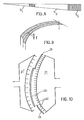
- the sole S 3 will be formed from juxtaposed boxes which are not offset with respect to each other, possibly secured by one or more bars 8, as shown in FIG. 3, or possibly a single box whose upper surface will be identical to that of the plurality of juxtaposed boxes.
- the racks D, the slides G, or the pivots F may belong to the boxes or be mounted on chassis integral with the boxes or with each group of boxes.
- the drive of the glass sheets will be by chain with cleats, or curved rods or others.
- An example of such a sole produced by the Applicant with boxes of standard thickness of 50 mm, firstly comprises a fixed sole S, of 3,300 mm in length, then an adjustable sole S 2 of conformation of 5,700 mm in length, formed by the juxtaposition of 114 identical boxes, but offset, and finally a cylindrical sole S 3 of 1000 mm, formed by the stack of 20 identical boxes not offset.
- the steps 1 are at most 0.29 mm to 250 mm from the axis, therefore of a very low height that the glass plates can easily cross.
- Such a sole can also be produced with curved rods with a spiral profile, in particular of a logarithmic spiral, or with a combination of boxes and curved rods.
- the quenching station comprises only such curved rods, conventional blowing means will be provided between said rods.
- FIG. 10 illustrates the application to vertical tempering of a glass sheet 20, of a box 21 according to the invention, having a logarithmic spiral profile.
- This box has on its surface nozzles 22, through which a gas can be blown in the direction of the sheet to be quenched.
- Flexible sealing plates 23 make it possible to mask the unused nozzles.
- one and the same box makes it possible to soak cylindrical sheets having different radii of curvature, bringing them opposite the surface portion of the box of average radius corresponding to their radius of curvature.
- a second box 21 ′ of shape complementary to the first box 21 can also be arranged on the other side of the glass sheet.
- the shape of the boxes can vary not only in a direction of the space in a spiral, but it can also vary in a spiral in the direction of the space perpendicular to the first.
- the bending of glass sheets in a vertical position is done with a shape and a counter shape having either logarithmic profiles in one direction, to make cylindrical bending, or logarithmic profiles in two directions (d profile 'a portion of torus), for bending in two different directions.
- bending elements described throughout this description or shown in the drawings constitute bending shapes or quenching boxes of convex shape. However, it is understood that the bending and / or quenching elements, whether they are curved rods or boxes, can also constitute concave shapes.
- the invention therefore provides a simple and practical means, applicable both to bending and to tempering of plates of a material in the plastic state, in particular of glass sheets, at a temperature equal to or higher than the softening temperature. glass.
- the glass sheets thus treated have optical qualities at least equal to those obtained with the devices of the prior art, the characteristics of which have been recalled above.
Landscapes
- Chemical & Material Sciences (AREA)
- Engineering & Computer Science (AREA)
- Materials Engineering (AREA)
- Organic Chemistry (AREA)
- Physics & Mathematics (AREA)
- Thermal Sciences (AREA)
- Shaping Of Tube Ends By Bending Or Straightening (AREA)
- Re-Forming, After-Treatment, Cutting And Transporting Of Glass Products (AREA)
Applications Claiming Priority (2)
| Application Number | Priority Date | Filing Date | Title |
|---|---|---|---|
| FR8012851A FR2483839A1 (fr) | 1980-06-10 | 1980-06-10 | Elements de bombage de plaques en un materiau a l'etat plastique, application de ces elements au bombage et a la trempe desdites plaques et dispositifs equipes de tels elements |
| FR8012851 | 1980-06-10 |
Publications (2)
| Publication Number | Publication Date |
|---|---|
| EP0041899A1 EP0041899A1 (fr) | 1981-12-16 |
| EP0041899B1 true EP0041899B1 (fr) | 1984-09-12 |
Family
ID=9242904
Family Applications (1)
| Application Number | Title | Priority Date | Filing Date |
|---|---|---|---|
| EP81400909A Expired EP0041899B1 (fr) | 1980-06-10 | 1981-06-09 | Eléments de bombage de plaques en un matériau à l'état plastique, application de ces éléments au bombage et à la trempe desdites plaques et dispositifs équipés de tels éléments |
Country Status (9)
| Country | Link |
|---|---|
| US (1) | US4378988A (Direct) |
| EP (1) | EP0041899B1 (Direct) |
| JP (1) | JPS5727931A (Direct) |
| BR (1) | BR8103641A (Direct) |
| CA (1) | CA1170458A (Direct) |
| DE (1) | DE3165988D1 (Direct) |
| ES (1) | ES502853A0 (Direct) |
| FR (1) | FR2483839A1 (Direct) |
| YU (1) | YU145381A (Direct) |
Families Citing this family (9)
| Publication number | Priority date | Publication date | Assignee | Title |
|---|---|---|---|---|
| FR2534243B1 (fr) * | 1982-10-11 | 1986-02-14 | Saint Gobain Vitrage | Procede pour le transport de feuilles de verre portees a leur temperature de deformation, son application au bombage et dispositif pour sa mise en oeuvre |
| US4853018A (en) * | 1987-11-23 | 1989-08-01 | Ford Motor Company | Method and apparatus for forming a glass sheet |
| US6014873A (en) * | 1990-09-26 | 2000-01-18 | Asahi Glass Company Ltd. | Process for bend-shaping a glass plate and an apparatus for bend-shaping the glass plate |
| EP0477913A3 (en) * | 1990-09-26 | 1993-04-07 | Asahi Glass Company Ltd. | Process and apparatus for bend-shaping glass plates |
| FR2691454B1 (fr) * | 1992-05-21 | 1994-07-08 | Saint Gobain Vitrage Int | Procede et dispositif d'obtention de feuilles de verre bombees. |
| KR100647198B1 (ko) * | 1998-10-21 | 2006-11-17 | 글래스텍 인코포레이티드 | 성형 유리판의 균등분배 급랭 |
| AT409301B (de) * | 2000-05-05 | 2002-07-25 | Ebner Peter Dipl Ing | Vorrichtung zum führen eines metallbandes auf einem gaskissen |
| GB0305655D0 (en) * | 2003-03-12 | 2003-04-16 | Renishaw Plc | Battery life determination |
| CN113631524B (zh) * | 2018-12-13 | 2023-04-11 | 康宁公司 | 运送设备和运送带 |
Family Cites Families (11)
| Publication number | Priority date | Publication date | Assignee | Title |
|---|---|---|---|---|
| FR1341005A (fr) * | 1961-09-22 | 1963-10-25 | Pittsburgh Plate Glass Co | Procédé et appareil pour bomber une feuille de verre |
| US3293015A (en) * | 1961-09-22 | 1966-12-20 | Pittsburgh Plate Glass Co | Method and apparatus for tempering glass sheets on a gas support bed |
| US3375094A (en) * | 1965-01-11 | 1968-03-26 | Permaglass | Method and apparatus for shaping glass or the like on a curved gas support bed |
| US3375093A (en) * | 1965-01-11 | 1968-03-26 | Permaglass | Method and apparatus for curving glass sheets or the like on a gas support bed |
| FR1476785A (fr) * | 1966-03-01 | 1967-04-14 | Saint Gobain | Perfectionnement au bombage de plaques de matières à l'état plastique |
| GB1190373A (en) * | 1966-04-25 | 1970-05-06 | Pilkington Brothers Ltd | Improvements in or relating to the Transporting of Glass Sheets |
| FR1520202A (fr) * | 1966-04-25 | 1968-04-05 | Pilkington Brothers Ltd | Perfectionnements au traitement de verre en feuilles |
| US3477839A (en) * | 1966-06-02 | 1969-11-11 | Ppg Industries Inc | Apparatus for bending glass sheets on a gas support bed |
| FR2221409A1 (en) * | 1973-03-12 | 1974-10-11 | Saint Gobain | Glass bending, on cantilevered rollers an angular relationship - to convey sheets or ribbon in a continuous process |
| FR2428616A1 (fr) * | 1978-06-15 | 1980-01-11 | Saint Gobain | Procede de reglage des tubes de caissons de soufflage destines a la trempe de feuilles de verre |
| US4311509A (en) * | 1980-09-26 | 1982-01-19 | Ppg Industries, Inc. | Apparatus for conveying glass sheets |
-
1980
- 1980-06-10 FR FR8012851A patent/FR2483839A1/fr active Granted
-
1981
- 1981-05-28 US US06/268,054 patent/US4378988A/en not_active Expired - Fee Related
- 1981-06-05 JP JP8585381A patent/JPS5727931A/ja active Pending
- 1981-06-08 CA CA000379281A patent/CA1170458A/fr not_active Expired
- 1981-06-08 ES ES502853A patent/ES502853A0/es active Granted
- 1981-06-09 BR BR8103641A patent/BR8103641A/pt unknown
- 1981-06-09 YU YU01453/81A patent/YU145381A/xx unknown
- 1981-06-09 DE DE8181400909T patent/DE3165988D1/de not_active Expired
- 1981-06-09 EP EP81400909A patent/EP0041899B1/fr not_active Expired
Also Published As
| Publication number | Publication date |
|---|---|
| BR8103641A (pt) | 1982-03-02 |
| ES8203263A1 (es) | 1982-04-01 |
| ES502853A0 (es) | 1982-04-01 |
| US4378988A (en) | 1983-04-05 |
| CA1170458A (fr) | 1984-07-10 |
| DE3165988D1 (en) | 1984-10-18 |
| YU145381A (en) | 1983-12-31 |
| FR2483839B1 (Direct) | 1982-06-18 |
| JPS5727931A (en) | 1982-02-15 |
| EP0041899A1 (fr) | 1981-12-16 |
| FR2483839A1 (fr) | 1981-12-11 |
Similar Documents
| Publication | Publication Date | Title |
|---|---|---|
| EP0015209B1 (fr) | Dispositif pour l'assemblage de feuilles de verre et/ou de matières plastiques | |
| EP0041899B1 (fr) | Eléments de bombage de plaques en un matériau à l'état plastique, application de ces éléments au bombage et à la trempe desdites plaques et dispositifs équipés de tels éléments | |
| EP0438328B1 (fr) | Dispositif pour l'assemblage par pressage des vitrages feuilletés | |
| EP1685073B1 (fr) | Procede et machine d'obtention de feuilles de verre bombees | |
| EP0316224A1 (fr) | Dispositif pour l'assemblage des vitrages feuilletés | |
| EP0640569A1 (fr) | Procédé et dispositif pour le bombage de feuilles de verre | |
| LU81929A1 (fr) | Procede et dispositif de bombage-trempe de feuilles de verre | |
| FR2568868A1 (fr) | Installation et procede pour bomber des plaques de verre | |
| FR2572387A1 (fr) | Formage de courbures composees par roulage | |
| FR2478066A1 (fr) | Procede et dispositif pour le formage de feuilles de verre a l'aide d'un moule a vide deformable | |
| EP3947302A1 (fr) | Convoyage de feuilles de verre par des rouleaux conformés | |
| CA2415572A1 (fr) | Procede et dispositif de bombage d'une feuille de verre | |
| BE1000065A6 (fr) | Procede et appareil de cambrage de feuilles de verre. | |
| EP0346198B1 (fr) | Amélioration des performances des installations de bombage et de trempe de plaques de verre à lit de conformation courbe dans la direction de défilement du verre | |
| EP0148043B1 (fr) | Dispositif pour le bombage de plaques de verre | |
| EP0007264A1 (fr) | Chaîne à un seul sens de courbure et application à une main courante | |
| EP0490789A1 (fr) | Procédé et dispositif de fabrication de faisceaux de fibres creuses semi-perméables pour appareils à membrane | |
| FR2594360A1 (fr) | Procede de cintrage d'elements ondules, machine pour la mise en oeuvre dudit procede, et elements ondules cintres obtenus | |
| EP0593363B1 (fr) | Procédé et installation de bombage de feuilles de verre | |
| EP0351288B1 (fr) | Dispositif pour l'assemblage des vitrages feuilletés | |
| EP0250311B1 (fr) | Procédé et dispositif pour le bombage de feuilles de verre | |
| FR2646627A1 (fr) | Derouleuse de troncs d'arbre avec dispositif antiflexion perfectionne | |
| FR2639623A1 (fr) | Procede et dispositif pour rassembler silencieusement des materiaux allonges | |
| EP0407323A1 (fr) | Procédé et dispositif de coulée continue entre cylindres de produits métalliques minces aptes au laminage à froid direct | |
| EP0493205A1 (fr) | Procédé et dispositif d'obtention de feuilles de verre bombées |
Legal Events
| Date | Code | Title | Description |
|---|---|---|---|
| PUAI | Public reference made under article 153(3) epc to a published international application that has entered the european phase |
Free format text: ORIGINAL CODE: 0009012 |
|
| AK | Designated contracting states |
Designated state(s): BE DE GB IT LU NL |
|
| 17P | Request for examination filed |
Effective date: 19820529 |
|
| ITF | It: translation for a ep patent filed | ||
| GRAA | (expected) grant |
Free format text: ORIGINAL CODE: 0009210 |
|
| AK | Designated contracting states |
Designated state(s): BE DE GB IT LU NL |
|
| REF | Corresponds to: |
Ref document number: 3165988 Country of ref document: DE Date of ref document: 19841018 |
|
| PLBE | No opposition filed within time limit |
Free format text: ORIGINAL CODE: 0009261 |
|
| STAA | Information on the status of an ep patent application or granted ep patent |
Free format text: STATUS: NO OPPOSITION FILED WITHIN TIME LIMIT |
|
| 26N | No opposition filed | ||
| ITTA | It: last paid annual fee | ||
| PGFP | Annual fee paid to national office [announced via postgrant information from national office to epo] |
Ref country code: NL Payment date: 19910630 Year of fee payment: 11 |
|
| PGFP | Annual fee paid to national office [announced via postgrant information from national office to epo] |
Ref country code: DE Payment date: 19910812 Year of fee payment: 11 |
|
| PGFP | Annual fee paid to national office [announced via postgrant information from national office to epo] |
Ref country code: BE Payment date: 19920326 Year of fee payment: 12 |
|
| PGFP | Annual fee paid to national office [announced via postgrant information from national office to epo] |
Ref country code: LU Payment date: 19920331 Year of fee payment: 12 |
|
| PGFP | Annual fee paid to national office [announced via postgrant information from national office to epo] |
Ref country code: GB Payment date: 19920507 Year of fee payment: 12 |
|
| EPTA | Lu: last paid annual fee | ||
| PG25 | Lapsed in a contracting state [announced via postgrant information from national office to epo] |
Ref country code: NL Effective date: 19930101 |
|
| NLV4 | Nl: lapsed or anulled due to non-payment of the annual fee | ||
| PG25 | Lapsed in a contracting state [announced via postgrant information from national office to epo] |
Ref country code: DE Effective date: 19930302 |
|
| PG25 | Lapsed in a contracting state [announced via postgrant information from national office to epo] |
Ref country code: LU Free format text: LAPSE BECAUSE OF NON-PAYMENT OF DUE FEES Effective date: 19930609 Ref country code: GB Effective date: 19930609 |
|
| PG25 | Lapsed in a contracting state [announced via postgrant information from national office to epo] |
Ref country code: BE Effective date: 19930630 |
|
| BERE | Be: lapsed |
Owner name: SAINT-GOBAIN VITRAGE Effective date: 19930630 |
|
| GBPC | Gb: european patent ceased through non-payment of renewal fee |
Effective date: 19930609 |