EP0040887B1 - Method and apparatus for treatment and hygienisation of sewage sludge and other organic sludges - Google Patents
Method and apparatus for treatment and hygienisation of sewage sludge and other organic sludges Download PDFInfo
- Publication number
- EP0040887B1 EP0040887B1 EP81200551A EP81200551A EP0040887B1 EP 0040887 B1 EP0040887 B1 EP 0040887B1 EP 81200551 A EP81200551 A EP 81200551A EP 81200551 A EP81200551 A EP 81200551A EP 0040887 B1 EP0040887 B1 EP 0040887B1
- Authority
- EP
- European Patent Office
- Prior art keywords
- sludge
- column
- pressure
- gas
- discharge
- Prior art date
- Legal status (The legal status is an assumption and is not a legal conclusion. Google has not performed a legal analysis and makes no representation as to the accuracy of the status listed.)
- Expired
Links
- 238000000034 method Methods 0.000 title claims abstract description 32
- 239000010801 sewage sludge Substances 0.000 title claims abstract description 4
- 239000010802 sludge Substances 0.000 claims abstract description 77
- 239000002360 explosive Substances 0.000 claims abstract description 4
- 239000007788 liquid Substances 0.000 claims description 16
- 239000007787 solid Substances 0.000 claims description 12
- XLYOFNOQVPJJNP-UHFFFAOYSA-N water Substances O XLYOFNOQVPJJNP-UHFFFAOYSA-N 0.000 claims description 12
- 239000002245 particle Substances 0.000 claims description 8
- 230000006837 decompression Effects 0.000 abstract description 6
- 238000010438 heat treatment Methods 0.000 abstract description 3
- 239000007789 gas Substances 0.000 description 32
- 210000004027 cell Anatomy 0.000 description 16
- 239000000203 mixture Substances 0.000 description 11
- 238000000926 separation method Methods 0.000 description 8
- 241000894006 Bacteria Species 0.000 description 6
- 230000000694 effects Effects 0.000 description 6
- 238000007254 oxidation reaction Methods 0.000 description 6
- 238000010521 absorption reaction Methods 0.000 description 5
- 238000005188 flotation Methods 0.000 description 5
- 230000008569 process Effects 0.000 description 5
- 239000000126 substance Substances 0.000 description 5
- 230000004075 alteration Effects 0.000 description 3
- QVGXLLKOCUKJST-UHFFFAOYSA-N atomic oxygen Chemical compound [O] QVGXLLKOCUKJST-UHFFFAOYSA-N 0.000 description 3
- 239000006285 cell suspension Substances 0.000 description 3
- 238000005516 engineering process Methods 0.000 description 3
- 238000009434 installation Methods 0.000 description 3
- 230000014759 maintenance of location Effects 0.000 description 3
- 239000001301 oxygen Substances 0.000 description 3
- 229910052760 oxygen Inorganic materials 0.000 description 3
- 239000002562 thickening agent Substances 0.000 description 3
- IJGRMHOSHXDMSA-UHFFFAOYSA-N Atomic nitrogen Chemical compound N#N IJGRMHOSHXDMSA-UHFFFAOYSA-N 0.000 description 2
- 239000002028 Biomass Substances 0.000 description 2
- 230000009172 bursting Effects 0.000 description 2
- 238000001035 drying Methods 0.000 description 2
- 238000000265 homogenisation Methods 0.000 description 2
- 229920006395 saturated elastomer Polymers 0.000 description 2
- 230000008719 thickening Effects 0.000 description 2
- 235000008733 Citrus aurantifolia Nutrition 0.000 description 1
- KWYUFKZDYYNOTN-UHFFFAOYSA-M Potassium hydroxide Chemical compound [OH-].[K+] KWYUFKZDYYNOTN-UHFFFAOYSA-M 0.000 description 1
- 235000011941 Tilia x europaea Nutrition 0.000 description 1
- 230000001580 bacterial effect Effects 0.000 description 1
- 244000052616 bacterial pathogen Species 0.000 description 1
- 210000000170 cell membrane Anatomy 0.000 description 1
- 210000002421 cell wall Anatomy 0.000 description 1
- 210000003850 cellular structure Anatomy 0.000 description 1
- 230000008859 change Effects 0.000 description 1
- 239000011362 coarse particle Substances 0.000 description 1
- 238000001816 cooling Methods 0.000 description 1
- 230000006378 damage Effects 0.000 description 1
- 230000029087 digestion Effects 0.000 description 1
- 238000005265 energy consumption Methods 0.000 description 1
- 238000009293 extended aeration Methods 0.000 description 1
- 239000003337 fertilizer Substances 0.000 description 1
- 238000007667 floating Methods 0.000 description 1
- 230000005484 gravity Effects 0.000 description 1
- 231100001261 hazardous Toxicity 0.000 description 1
- 230000002147 killing effect Effects 0.000 description 1
- 239000004571 lime Substances 0.000 description 1
- 239000007791 liquid phase Substances 0.000 description 1
- 239000000463 material Substances 0.000 description 1
- 239000012528 membrane Substances 0.000 description 1
- 239000002184 metal Substances 0.000 description 1
- 229910052757 nitrogen Inorganic materials 0.000 description 1
- 239000011368 organic material Substances 0.000 description 1
- 230000003204 osmotic effect Effects 0.000 description 1
- 230000003647 oxidation Effects 0.000 description 1
- 238000009928 pasteurization Methods 0.000 description 1
- 239000012071 phase Substances 0.000 description 1
- 230000000704 physical effect Effects 0.000 description 1
- 229920000642 polymer Polymers 0.000 description 1
- 229940072033 potash Drugs 0.000 description 1
- 235000015320 potassium carbonate Nutrition 0.000 description 1
- BWHMMNNQKKPAPP-UHFFFAOYSA-L potassium carbonate Substances [K+].[K+].[O-]C([O-])=O BWHMMNNQKKPAPP-UHFFFAOYSA-L 0.000 description 1
- 239000000047 product Substances 0.000 description 1
- 230000002035 prolonged effect Effects 0.000 description 1
- 230000009467 reduction Effects 0.000 description 1
- 150000003839 salts Chemical class 0.000 description 1
- 238000004513 sizing Methods 0.000 description 1
- 230000003068 static effect Effects 0.000 description 1
- 239000006228 supernatant Substances 0.000 description 1
- 231100000331 toxic Toxicity 0.000 description 1
- 230000002588 toxic effect Effects 0.000 description 1
- 238000004065 wastewater treatment Methods 0.000 description 1
Images
Classifications
-
- C—CHEMISTRY; METALLURGY
- C02—TREATMENT OF WATER, WASTE WATER, SEWAGE, OR SLUDGE
- C02F—TREATMENT OF WATER, WASTE WATER, SEWAGE, OR SLUDGE
- C02F11/00—Treatment of sludge; Devices therefor
- C02F11/12—Treatment of sludge; Devices therefor by de-watering, drying or thickening
Definitions
- the invention relates to a method for the hygienisation of sewage sludge and other organic sludges by separating it into water and solid particles, which method comprises pressurisation of the sludge with a gas such as air and releasing said pressure.
- the sludge may contain hazardous pathogenic bacteria.
- the extended aeration technology serves to obtain selfdestruction of the biomass resulting in reduction of bacteria population and sludge volume. Digestion of sludge is also practised at a temperature of approx. 35 degr. C. under anaerobic conditions. This process takes two to three weeks and organic components are partly converted into CO 2 , H 2 0'and CH 4 .
- Heat treatment methods are known as well like:
- Aim of the invention is to provide a method with which all these problems can be solved in an extreme simple way.
- this is achieved in that the absorbed gas containing sludge is passed through a discharge device of a pressurized vessel by the pressure of the pressurizing gas and the pressure release is a semi-explosive pressure drop of each sludge quantity immediately behind said device after having passed said device and upon entering a space of substantially lower pressure such as atmospheric pressure.
- the quantity of gas that can be dissolved is direct proportional with the pressure applied.
- Preferable is compressed air, but other gases can be .used as well.
- oxygen when oxygen is used a pre- killing effect is obtained as this gas is toxic towards the biological sludge mass. In case light with short wavelength in combination is used the effect can be dramatically increased.
- the process is executed with an overpressure between 7 and 70 bar.
- the gasabsorption means that the gas penetrates into the cells of the organic material and bacteria.
- the pressure is suddenly released, resulting in bursting of the cells because the gas that is absorbed during a certain period of time has no time to escape in an equal time period.
- This cell bursting means that they are destroyed; this also means destroying of the bacteria and besides this it also results in liberation of the cellwater, the capillar water and separation of the colloidal suspended solids.
- the method according to the invention is not only resulting in destruction of cell structures and consequently of bacteria, but at the same time in a flotating separation as a result of which the liberated solids do not sink but float. A proper separation of water and remaining solids can be achieved afterwards in a simple way by using a flotation unit.
- the method can be executed in such a way that primarily a pressurized vessel is filled with sludge, batch wise, and after gas absorption a discharge valve is suddenly opened and a batch or part of it can escape. It is also possible to operate on a continuous basis by means of a controlled discharge unit, provided that the pressure and liquid level is kept constant.
- the method according to the invention is surprisingly simple; what is required is just an installation to pressurize the sludge and air and an installation to add the compressed air to the sludge.
- the invention thus relates to an apparatus to execute the method and consists of a column with a sludge feed at the topmost part and sludge discharge at the bottom part, which column is provided with trays arranged cascade wise or equal means to divide the sludge into thin layers, which column is connected to a source of pressurized gas that can be disconnected, which connection is situated between sludge feed and discharge.
- the method is insensitive to dry solids concentrations; all organic mixtures can be treated on condition that they are free flowing liquids.
- Tests have been executed with pressure between 40 and 50 bars and a calculated energy consumption of approx. 2.5 kWh per m 3 of liquid. It is possible to operate with low pressure, but with high pressure as well. Selection of operating pressure is predetermined by the sludge characteristic and retention time of the sludge in the system which offers an optimum in processing. If low pressure is preferred, improved results can be obtained e.g. by adding chemicals, such as potash to the mixture, resulting in lower osmotic pressure of the mixture in comparison with the cell liquid itself. The cells will show a preswelling effect. this phenomenon however is known in the respective art.
- the efficiency of cell rupture depends on the physical properties of the different bacteria species, the age of the biomass, the pressure applied and the degree of gas saturation of the cell suspension.
- the air applied for cell fractionating is liberated after pressure release and now functions as flotating medium for the treated sludge particles. Innumerable tiny air bubbles are spontaneously formed throughout the liquid and force the treated particles to the surface resulting in an intense floating effect. Tests have indicated that 50% of the original sludge volume can be separated as clean white water from the original sludge with e.g. 4-5% dry solids.
- flotation thickeners can be used and centrifuges or beltfilter-presses in case further dewatering is required.
- the apparatus for execution of the process according to the invention can be fully automated.
- the discharge unit is automatically controlled by a level controller that is connected to the column and adjusted to a predetermined level setting.
- Purpose of the sludge retention time is to expose the mixture sufficiently long to the pressurized gas/sludge mixture, in order to enable the dissolved gas in the liquid to penetrate through the cell membranes (walls) into the cell liquid.
- connection of the pressurized gas source is located between sludge entrance and discharge, but preferably in the gas zone itself.
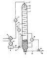
- This drawing indicates a column 1, provided with. a number of trays 2, that ensure a cascade wise down flow of the sludge that enters the column at 3 thus creating a maximum of free surface area and holding time of the liquid to obtain optimal exposure to the pressurized gas that enters the column at 4.
- the sludge feed takes place with pump 5 and pipe 6 to the entrance 3 of column 1.
- a flow indicator 7 is installed by which the sludge flow is measured and indicated. An alarm signal will indicate when pump 5 is malfunctioning.
- a multi-stage air compressor is installed supplying compressed air to the column through air- vessel 9, a pipe 10 and connection 4.
- Pipe 10 is provided with a valve 11 that is automatically controlled by pressure indicator 12, controlling the pressure level at a predetermined setting.
- the column 1 is provided with a discharge pipe 13 and valve 14 which valve has a discharge pipe 15, preferably connected to a flotation tank which is not indicated.
- This valve 14 can be controlled automatically by level controller 16 measuring the liquid level in column 1 continuously.
- the level controller 16 controls valve 14 in such a way that the sludge mixture 17 is evacuated by using the gaspressure in column 1; the sludge is kept at a constant level.
- Pump 5 will feed the sludge from a sludge holding tank or sludge thickener, in which some thickening has already taken place into column 1; the flow can easily be adjusted by a variable drive.
- Sludge pump 5 must be able to feed the sludge into .the pressurized saturation column 1 and therefore must have a max.
- discharge pressure of e.g. 50 bar.
- a piston or piston membrane pump can be used for this purpose.
- the sludge enters at 3 and hits the splashplate 18 to increase liquid/gas contact area; more gas absorption takes place by passing cascade trays 2 during downward flow. During this downward flow sufficient time is available to saturate the sludge with gas.
- the cell suspension In the undermost part of column 1 the cell suspension is enabled to absorb gas through cell walls and when this has taken place after e.g. 5 minutes, discharge can take place.
- This discharge preferably is located slightly above the bottom 1.9 to collect coarse particles. This part should be provided with a cleaning-out cover to remove these particles.
- Discharge valve 14 can be automatically controlled by a level controiier 16 measuring the static height of the liquid column; this column height has a relationship to the sludge retention time required for proper absorption of gas into the cell suspension.
- Pressurized air can be admitted at any place between sludge feed and sludge discharge.
- a connection in the gas zone is preferred to prevent sludge entering the gas piping system when the gas system is off pressure or during idle time of the plant.
- the air compressor 8 can be a normal multi stage unit suitable for e.g. 60 bar max. discharge pressure. A volume of 1 Nm3 atmospheric air per m3 of sludge is a reasonable sizing parameter.
- the efficiency of the compressed gas that is supplied to column 1 is 100% since gas is only discharged by the saturated sludge mixture itself.
- Method and apparatus according to the invention can be easily stopped and started; these operations can be executed in a very short time.
- the plant can stand idle under full operating pressure without any loss of energy. Absence of heat will give no physical alterations, nor fouling or scaling of the system will take place.
Landscapes
- Life Sciences & Earth Sciences (AREA)
- Hydrology & Water Resources (AREA)
- Engineering & Computer Science (AREA)
- Environmental & Geological Engineering (AREA)
- Water Supply & Treatment (AREA)
- Chemical & Material Sciences (AREA)
- Organic Chemistry (AREA)
- Treatment Of Sludge (AREA)
Abstract
Description
- The invention relates to a method for the hygienisation of sewage sludge and other organic sludges by separating it into water and solid particles, which method comprises pressurisation of the sludge with a gas such as air and releasing said pressure.
- Such a method is known from Swiss Patent Specification 534,639. According to said known method the sludge is pressurized within a tank and after sufficient time allowing the absorption of the gas the pressure is released. This pressure release only means that the gas is allowed to escape from the tank. Pressurisation and pressure release can be repeated and the result is a separation of the sludge into water and solid particles. A similar method has been described in German Patent Specification 2,243,861 which also mentions that upon pressure release the gas bubbles may generate a floatation effect, moving the solid particles of the sludge towards the water surface.
- This known method is not very effective because pressure drop requires too much time. The result is that separation is insufficient and bacteria are not destroyed.
- The problem of treatment and hygienisation of sludge, as residual product of wastewater treatment, is very old. The easiest and cheapest way to dispose of this sludge is sea dumping or storage on drying beds, by which the sludge is exposed to a prolonged natural thickening process before it can be removed.
- Sea dumping results in pollution of the sea, especially when this takes place near the coast and coastal seacurrents exist, while sea dumping at greater distance will dramatically increase transportation costs. Land area for drying beds is scarce in places with a high population, whilst just these places produce the greatest sludge volumes.
- The sludge may contain hazardous pathogenic bacteria.
- Many mechanical and chemical methods exist to change the properties of the sludge and to make it useful for other purposes like fertilizer.
- The extended aeration technology serves to obtain selfdestruction of the biomass resulting in reduction of bacteria population and sludge volume. Digestion of sludge is also practised at a temperature of approx. 35 degr. C. under anaerobic conditions. This process takes two to three weeks and organic components are partly converted into CO2, H20'and CH4.
- It is further practised, to increase dewater- ability and to effect the bacterial level, to add chemicals like lime, metal salts and/or polymeres.
- Heat treatment methods are known as well like:
- a) pasteurisation at a temperature between 70 and 75°C under slight overpressure.
- b) treatment under higher pressure, between 25 and 30 bars at a temperature of 200°C, and treatment with partial or complete oxydation by which operating pressures between 25 and 125 bars are used at temperatures between 190 and 280°C; at the same time air is introduced to obtain oxydation.
- Examples of last mentioned methods can be found in the Dutch . patent 144.560 and published Dutch patent application 149.768. All known methods have quite a number of disadvantages such as high energy requirement, high investment costs, high operating costs, highly polluted supernatant liquor, odour nuisance, increase of sludge volume as a result of adding chemicals, fouling of the installation especially at higher temperatures etc.
- Aim of the invention is to provide a method with which all these problems can be solved in an extreme simple way.
- According to the invention this is achieved in that the absorbed gas containing sludge is passed through a discharge device of a pressurized vessel by the pressure of the pressurizing gas and the pressure release is a semi-explosive pressure drop of each sludge quantity immediately behind said device after having passed said device and upon entering a space of substantially lower pressure such as atmospheric pressure.
- The quantity of gas that can be dissolved is direct proportional with the pressure applied. Preferable is compressed air, but other gases can be .used as well. In this respect it is mentioned that when oxygen is used a pre- killing effect is obtained as this gas is toxic towards the biological sludge mass. In case light with short wavelength in combination is used the effect can be dramatically increased. Preferably the process is executed with an overpressure between 7 and 70 bar.
- The gasabsorption means that the gas penetrates into the cells of the organic material and bacteria. When the mixture has balanced out concerning pressure and corresponding gas absorption capacity, the pressure is suddenly released, resulting in bursting of the cells because the gas that is absorbed during a certain period of time has no time to escape in an equal time period. This cell bursting means that they are destroyed; this also means destroying of the bacteria and besides this it also results in liberation of the cellwater, the capillar water and separation of the colloidal suspended solids. The method according to the invention is not only resulting in destruction of cell structures and consequently of bacteria, but at the same time in a flotating separation as a result of which the liberated solids do not sink but float. A proper separation of water and remaining solids can be achieved afterwards in a simple way by using a flotation unit.
- The method can be executed in such a way that primarily a pressurized vessel is filled with sludge, batch wise, and after gas absorption a discharge valve is suddenly opened and a batch or part of it can escape. It is also possible to operate on a continuous basis by means of a controlled discharge unit, provided that the pressure and liquid level is kept constant.
- The method according to the invention is surprisingly simple; what is required is just an installation to pressurize the sludge and air and an installation to add the compressed air to the sludge. The invention thus relates to an apparatus to execute the method and consists of a column with a sludge feed at the topmost part and sludge discharge at the bottom part, which column is provided with trays arranged cascade wise or equal means to divide the sludge into thin layers, which column is connected to a source of pressurized gas that can be disconnected, which connection is situated between sludge feed and discharge.
- When cell material is disrupted, no chemical or physical alterations of cell components will take place. Superheating cannot take place, in contrary, the adiabatical expansion will result in cooling of the liquid. The efficiency of cell disruption depends on the pressure applied. At higher pressure larger amounts of air will be dissolved in the cells and a high degree of cell disruption can be expected. Decompression of the sludge can be executed in a simple way by means of a special homogenizing discharge unit at the bottom part of the column. When this unit is opened or when a controlled discharge will take place, the gas-saturated mixture is evacuated to atmospheric conditions. When this takes place the available pressure energy in the liquid will be converted into kinetic energy and creates an extreme violence in the sludge mass, respectively results in high liquid velocities, turbulence and shearforces, so that an homogenization effect will result.
- When operating at high pressure, in this respect velocities as high as that of sound can be achieved. The large volume of air that is absorbed under force will be separated from the sludge after passing the discharge unit in a semi-explosive way. The alterations in sludge structure obtained, physically result in a uniformity in size of the sludge particles which is of extreme importance for improved flotation as a means to create maximum water separation; the types and other water binding properties of the different types of sludge like free water, adsorbed- and capillar water, intra cellular- and colloidal water are strongly effected by this homogenization procedure. With the proposed technology the compactness and the in- homogenity of the sludge is destroyed and an improved separation of solids and liquid is obtained; with the elevated pressure technology it is now made possible to flotate all types of sludge or mixtures of it in a satisfactorily way and will increase dry solids concentration considerably. As a result of this, final sludge volume will be reduced to at least 50% of the original underflow from e.g. a gravity thickener which outcome is obtained after extensive testwork.
- The method is insensitive to dry solids concentrations; all organic mixtures can be treated on condition that they are free flowing liquids.
- Tests have been executed with pressure between 40 and 50 bars and a calculated energy consumption of approx. 2.5 kWh per
m 3 of liquid. It is possible to operate with low pressure, but with high pressure as well. Selection of operating pressure is predetermined by the sludge characteristic and retention time of the sludge in the system which offers an optimum in processing. If low pressure is preferred, improved results can be obtained e.g. by adding chemicals, such as potash to the mixture, resulting in lower osmotic pressure of the mixture in comparison with the cell liquid itself. The cells will show a preswelling effect. this phenomenon however is known in the respective art. - The efficiency of cell rupture depends on the physical properties of the different bacteria species, the age of the biomass, the pressure applied and the degree of gas saturation of the cell suspension.
- The air applied for cell fractionating is liberated after pressure release and now functions as flotating medium for the treated sludge particles. Innumerable tiny air bubbles are spontaneously formed throughout the liquid and force the treated particles to the surface resulting in an intense floating effect. Tests have indicated that 50% of the original sludge volume can be separated as clean white water from the original sludge with e.g. 4-5% dry solids.
- For separation purposes flotation thickeners can be used and centrifuges or beltfilter-presses in case further dewatering is required.
- The apparatus for execution of the process according to the invention can be fully automated. Preferably the discharge unit is automatically controlled by a level controller that is connected to the column and adjusted to a predetermined level setting.
- Purpose of the sludge retention time is to expose the mixture sufficiently long to the pressurized gas/sludge mixture, in order to enable the dissolved gas in the liquid to penetrate through the cell membranes (walls) into the cell liquid.
- The connection of the pressurized gas source is located between sludge entrance and discharge, but preferably in the gas zone itself.
- Forementioned methods from the Dutch patent 144.560 and the published Dutch patent application 149.768 which describe the thermal oxidation sludge treatment also operate with high pressure. These pressures however in the first place serve to secure that the liquid phase of the sludge will not be converted into a gas phase at the respective temperature. The introduction of pressurized air serves to partly oxydize the sludge mixture. This oxydation serves to destroy cells and is obtained by heating in presence of oxygen. Disruption of cells by rapid decompression does not take place. The cells are already destroyed as a result of temperature elevation and oxydation before pressure is released. After being discharged, consequently no flotation but settlement of the solids will take place.
- With the method according to the invention also gases that do not contain oxygen can be used like nitrogen; this is not possible with the wet oxydation process. The invention now will be further explained and reference is made to the pertaining sketch on which the principle of the invention schematically is shown.
- This drawing indicates a column 1, provided with. a number of
trays 2, that ensure a cascade wise down flow of the sludge that enters the column at 3 thus creating a maximum of free surface area and holding time of the liquid to obtain optimal exposure to the pressurized gas that enters the column at 4. The sludge feed takes place with pump 5 and pipe 6 to theentrance 3 of column 1. In pipe 6 a flow indicator 7 is installed by which the sludge flow is measured and indicated. An alarm signal will indicate when pump 5 is malfunctioning. At 8 a multi-stage air compressor is installed supplying compressed air to the column through air- vessel 9, a pipe 10 and connection 4. Pipe 10 is provided with avalve 11 that is automatically controlled bypressure indicator 12, controlling the pressure level at a predetermined setting. The column 1 is provided with adischarge pipe 13 andvalve 14 which valve has adischarge pipe 15, preferably connected to a flotation tank which is not indicated. Thisvalve 14 can be controlled automatically by level controller 16 measuring the liquid level in column 1 continuously. The level controller 16controls valve 14 in such a way that thesludge mixture 17 is evacuated by using the gaspressure in column 1; the sludge is kept at a constant level. Pump 5 will feed the sludge from a sludge holding tank or sludge thickener, in which some thickening has already taken place into column 1; the flow can easily be adjusted by a variable drive. Sludge pump 5 must be able to feed the sludge into .the pressurized saturation column 1 and therefore must have a max. discharge pressure of e.g. 50 bar. A piston or piston membrane pump can be used for this purpose. The sludge enters at 3 and hits thesplashplate 18 to increase liquid/gas contact area; more gas absorption takes place by passingcascade trays 2 during downward flow. During this downward flow sufficient time is available to saturate the sludge with gas. In the undermost part of column 1 the cell suspension is enabled to absorb gas through cell walls and when this has taken place after e.g. 5 minutes, discharge can take place. This discharge preferably is located slightly above the bottom 1.9 to collect coarse particles. This part should be provided with a cleaning-out cover to remove these particles. -
Discharge valve 14 can be automatically controlled by a level controiier 16 measuring the static height of the liquid column; this column height has a relationship to the sludge retention time required for proper absorption of gas into the cell suspension. - Pressurized air can be admitted at any place between sludge feed and sludge discharge. A connection in the gas zone is preferred to prevent sludge entering the gas piping system when the gas system is off pressure or during idle time of the plant.
- The
air compressor 8 can be a normal multi stage unit suitable for e.g. 60 bar max. discharge pressure. A volume of 1 Nm3 atmospheric air per m3 of sludge is a reasonable sizing parameter. - The efficiency of the compressed gas that is supplied to column 1 is 100% since gas is only discharged by the saturated sludge mixture itself.
- Method and apparatus according to the invention can be easily stopped and started; these operations can be executed in a very short time. The plant can stand idle under full operating pressure without any loss of energy. Absence of heat will give no physical alterations, nor fouling or scaling of the system will take place.
Claims (4)
Priority Applications (1)
| Application Number | Priority Date | Filing Date | Title |
|---|---|---|---|
| AT81200551T ATE6765T1 (en) | 1980-05-22 | 1981-05-21 | METHOD AND DEVICE FOR THE TREATMENT AND SANITIZATION OF SEWAGE SLUDGE AND OTHER ORGANIC SLUDGE. |
Applications Claiming Priority (2)
| Application Number | Priority Date | Filing Date | Title |
|---|---|---|---|
| NL8002971 | 1980-05-22 | ||
| NL8002971 | 1980-05-22 |
Publications (2)
| Publication Number | Publication Date |
|---|---|
| EP0040887A1 EP0040887A1 (en) | 1981-12-02 |
| EP0040887B1 true EP0040887B1 (en) | 1984-03-21 |
Family
ID=19835348
Family Applications (1)
| Application Number | Title | Priority Date | Filing Date |
|---|---|---|---|
| EP81200551A Expired EP0040887B1 (en) | 1980-05-22 | 1981-05-21 | Method and apparatus for treatment and hygienisation of sewage sludge and other organic sludges |
Country Status (3)
| Country | Link |
|---|---|
| EP (1) | EP0040887B1 (en) |
| AT (1) | ATE6765T1 (en) |
| DE (1) | DE3162767D1 (en) |
Families Citing this family (11)
| Publication number | Priority date | Publication date | Assignee | Title |
|---|---|---|---|---|
| DE3524896A1 (en) * | 1985-07-12 | 1987-01-22 | Linde Ag | METHOD AND DEVICE FOR ANAEROBIC BIOLOGICAL CLEANING OF ORGANICALLY DAMAGED LIQUIDS AND / OR LIQUID-SOLID MIXTURES |
| GB8623428D0 (en) * | 1986-09-30 | 1986-11-05 | East Anglian Water Co | Treatment of water |
| US5549922A (en) * | 1989-04-24 | 1996-08-27 | Juchem Gmbh | Method of making flour-containing edible semifinished products |
| US5639441A (en) * | 1992-03-06 | 1997-06-17 | Board Of Regents Of University Of Colorado | Methods for fine particle formation |
| US5288462A (en) * | 1992-05-18 | 1994-02-22 | Stephen D. Carter | Sterilization apparatus and method |
| US5686045A (en) * | 1994-02-09 | 1997-11-11 | Carter; Stephen D. | Method for the heat independent sterilization of microbially contaminated instruments |
| US6120732A (en) * | 1997-06-23 | 2000-09-19 | University Of Georgia Research Foundation, Inc. | Microbial inactivation by high-pressure throttling |
| US6447718B1 (en) | 1999-11-10 | 2002-09-10 | Stephen Douglas Carter | Apparatus and associated method for decontaminating contaminated matter with ultrasonic transient cavitation |
| FR2966819B1 (en) * | 2010-10-29 | 2013-12-27 | Orege | METHOD AND DEVICE FOR CLARIFYING WATER. |
| FR2966818B1 (en) * | 2010-10-29 | 2014-02-14 | Orege | METHOD FOR SEPARATION BETWEEN LIQUID AND SUSPENDED MATERIAL OF A SLURRY AND DEVICE USING SUCH A METHOD |
| GB2573842A (en) * | 2018-01-10 | 2019-11-20 | Surinder Pal Grewal Simon | Improvements in or relating to decontamination |
Family Cites Families (4)
| Publication number | Priority date | Publication date | Assignee | Title |
|---|---|---|---|---|
| DE265720C (en) * | ||||
| DE2019731C3 (en) * | 1970-04-20 | 1974-11-21 | Ver Kesselwerke Ag | Process for treating sewage sludge to improve its drainage properties and device for carrying out the process |
| CH534639A (en) * | 1971-02-03 | 1973-03-15 | Gut Ulrich | Pressure-treatment of effluent muds - to liberate water bound to colloidal substances |
| DE2243861A1 (en) * | 1972-09-07 | 1974-03-14 | Ludwig Dipl Ing Dr Tech Csepai | Biological sewage treatment - using pressurized mixing of raw sewage with activated sludge and air followed by expansion |
-
1981
- 1981-05-21 EP EP81200551A patent/EP0040887B1/en not_active Expired
- 1981-05-21 DE DE8181200551T patent/DE3162767D1/en not_active Expired
- 1981-05-21 AT AT81200551T patent/ATE6765T1/en not_active IP Right Cessation
Also Published As
| Publication number | Publication date |
|---|---|
| EP0040887A1 (en) | 1981-12-02 |
| ATE6765T1 (en) | 1984-04-15 |
| DE3162767D1 (en) | 1984-04-26 |
Similar Documents
| Publication | Publication Date | Title |
|---|---|---|
| EP0040887B1 (en) | Method and apparatus for treatment and hygienisation of sewage sludge and other organic sludges | |
| US4009098A (en) | Waste treatment process | |
| US4053399A (en) | Method and system for waste treatment | |
| US4009105A (en) | Waste treatment apparatus | |
| AU683533B2 (en) | Unit for treating water by ozonation, and corresponding ozonised water production apparatus | |
| US4632758A (en) | Anaerobic wastewater treatment system | |
| CA2337975C (en) | Wastewater treatment system | |
| US4521310A (en) | Apparatus and method for the treatment of organic wastes | |
| US3724667A (en) | Activated sludge process and system | |
| US4069149A (en) | Continuous fermentation process and apparatus | |
| US3745113A (en) | Biological decomposition of organic material | |
| US2809933A (en) | Biological purification system | |
| US7527734B1 (en) | Rapid non-equilibrium decompression of microorganism-containing waste streams | |
| US4695388A (en) | Apparatus and process for rapid sewage sludge separation | |
| US3368967A (en) | Process for treatment of sludge and apparatus therefor | |
| US3476250A (en) | Transportable sewage treating apparatus | |
| CA2336678C (en) | Method and apparatus for treating liquid, particularly with ultrasonic vibrations | |
| US4265753A (en) | Aeration filtration tank and water treatment system | |
| NO783595L (en) | SLUDGE TREATMENT PROCEDURES AND DEVICES | |
| USRE30944E (en) | Continuous fermentation process and apparatus | |
| JPS5586586A (en) | Treating method of sewage | |
| US11878924B2 (en) | Process and device for anaerobic purification | |
| JPS5775194A (en) | Treatment of organic waste | |
| JPH11192497A (en) | Waste water treating device utilizing microorganism | |
| JPH04293598A (en) | Solid-liquid separation method for fermentable organic liquid matter and sludge treatment apparatus using the same method |
Legal Events
| Date | Code | Title | Description |
|---|---|---|---|
| PUAI | Public reference made under article 153(3) epc to a published international application that has entered the european phase |
Free format text: ORIGINAL CODE: 0009012 |
|
| AK | Designated contracting states |
Designated state(s): AT BE CH DE FR GB IT NL SE |
|
| 17P | Request for examination filed |
Effective date: 19820517 |
|
| ITF | It: translation for a ep patent filed | ||
| GRAA | (expected) grant |
Free format text: ORIGINAL CODE: 0009210 |
|
| AK | Designated contracting states |
Designated state(s): AT BE CH DE FR GB IT LI NL SE |
|
| REF | Corresponds to: |
Ref document number: 6765 Country of ref document: AT Date of ref document: 19840415 Kind code of ref document: T |
|
| REF | Corresponds to: |
Ref document number: 3162767 Country of ref document: DE Date of ref document: 19840426 |
|
| ET | Fr: translation filed | ||
| PLBE | No opposition filed within time limit |
Free format text: ORIGINAL CODE: 0009261 |
|
| STAA | Information on the status of an ep patent application or granted ep patent |
Free format text: STATUS: NO OPPOSITION FILED WITHIN TIME LIMIT |
|
| 26N | No opposition filed | ||
| ITTA | It: last paid annual fee | ||
| PGFP | Annual fee paid to national office [announced via postgrant information from national office to epo] |
Ref country code: GB Payment date: 19930521 Year of fee payment: 13 |
|
| PGFP | Annual fee paid to national office [announced via postgrant information from national office to epo] |
Ref country code: FR Payment date: 19930525 Year of fee payment: 13 |
|
| PGFP | Annual fee paid to national office [announced via postgrant information from national office to epo] |
Ref country code: SE Payment date: 19930526 Year of fee payment: 13 Ref country code: CH Payment date: 19930526 Year of fee payment: 13 |
|
| PGFP | Annual fee paid to national office [announced via postgrant information from national office to epo] |
Ref country code: AT Payment date: 19930528 Year of fee payment: 13 |
|
| PGFP | Annual fee paid to national office [announced via postgrant information from national office to epo] |
Ref country code: NL Payment date: 19930531 Year of fee payment: 13 |
|
| PGFP | Annual fee paid to national office [announced via postgrant information from national office to epo] |
Ref country code: DE Payment date: 19930602 Year of fee payment: 13 |
|
| PGFP | Annual fee paid to national office [announced via postgrant information from national office to epo] |
Ref country code: BE Payment date: 19930628 Year of fee payment: 13 |
|
| PG25 | Lapsed in a contracting state [announced via postgrant information from national office to epo] |
Ref country code: GB Effective date: 19940521 Ref country code: AT Effective date: 19940521 |
|
| PG25 | Lapsed in a contracting state [announced via postgrant information from national office to epo] |
Ref country code: SE Effective date: 19940522 |
|
| PG25 | Lapsed in a contracting state [announced via postgrant information from national office to epo] |
Ref country code: LI Effective date: 19940531 Ref country code: CH Effective date: 19940531 Ref country code: BE Effective date: 19940531 |
|
| BERE | Be: lapsed |
Owner name: SCHMIDT JAN Effective date: 19940531 |
|
| PG25 | Lapsed in a contracting state [announced via postgrant information from national office to epo] |
Ref country code: NL Effective date: 19941201 |
|
| NLV4 | Nl: lapsed or anulled due to non-payment of the annual fee | ||
| GBPC | Gb: european patent ceased through non-payment of renewal fee |
Effective date: 19940521 |
|
| EUG | Se: european patent has lapsed |
Ref document number: 81200551.0 Effective date: 19941210 |
|
| PG25 | Lapsed in a contracting state [announced via postgrant information from national office to epo] |
Ref country code: FR Effective date: 19950131 |
|
| REG | Reference to a national code |
Ref country code: CH Ref legal event code: PL |
|
| PG25 | Lapsed in a contracting state [announced via postgrant information from national office to epo] |
Ref country code: DE Effective date: 19950201 |
|
| EUG | Se: european patent has lapsed |
Ref document number: 81200551.0 |
|
| REG | Reference to a national code |
Ref country code: FR Ref legal event code: ST |