EP0040868B1 - Verfahren zur Herstellung von Synthesegas - Google Patents
Verfahren zur Herstellung von Synthesegas Download PDFInfo
- Publication number
- EP0040868B1 EP0040868B1 EP81200474A EP81200474A EP0040868B1 EP 0040868 B1 EP0040868 B1 EP 0040868B1 EP 81200474 A EP81200474 A EP 81200474A EP 81200474 A EP81200474 A EP 81200474A EP 0040868 B1 EP0040868 B1 EP 0040868B1
- Authority
- EP
- European Patent Office
- Prior art keywords
- reactor
- fuel
- oxygen
- synthesis gas
- gas
- Prior art date
- Legal status (The legal status is an assumption and is not a legal conclusion. Google has not performed a legal analysis and makes no representation as to the accuracy of the status listed.)
- Expired
Links
Images
Classifications
-
- C—CHEMISTRY; METALLURGY
- C10—PETROLEUM, GAS OR COKE INDUSTRIES; TECHNICAL GASES CONTAINING CARBON MONOXIDE; FUELS; LUBRICANTS; PEAT
- C10J—PRODUCTION OF PRODUCER GAS, WATER-GAS, SYNTHESIS GAS FROM SOLID CARBONACEOUS MATERIAL, OR MIXTURES CONTAINING THESE GASES; CARBURETTING AIR OR OTHER GASES
- C10J3/00—Production of combustible gases containing carbon monoxide from solid carbonaceous fuels
- C10J3/46—Gasification of granular or pulverulent flues in suspension
- C10J3/48—Apparatus; Plants
- C10J3/50—Fuel charging devices
- C10J3/506—Fuel charging devices for entrained flow gasifiers
-
- C—CHEMISTRY; METALLURGY
- C10—PETROLEUM, GAS OR COKE INDUSTRIES; TECHNICAL GASES CONTAINING CARBON MONOXIDE; FUELS; LUBRICANTS; PEAT
- C10J—PRODUCTION OF PRODUCER GAS, WATER-GAS, SYNTHESIS GAS FROM SOLID CARBONACEOUS MATERIAL, OR MIXTURES CONTAINING THESE GASES; CARBURETTING AIR OR OTHER GASES
- C10J3/00—Production of combustible gases containing carbon monoxide from solid carbonaceous fuels
- C10J3/46—Gasification of granular or pulverulent flues in suspension
- C10J3/54—Gasification of granular or pulverulent fuels by the Winkler technique, i.e. by fluidisation
- C10J3/56—Apparatus; Plants
-
- C—CHEMISTRY; METALLURGY
- C10—PETROLEUM, GAS OR COKE INDUSTRIES; TECHNICAL GASES CONTAINING CARBON MONOXIDE; FUELS; LUBRICANTS; PEAT
- C10J—PRODUCTION OF PRODUCER GAS, WATER-GAS, SYNTHESIS GAS FROM SOLID CARBONACEOUS MATERIAL, OR MIXTURES CONTAINING THESE GASES; CARBURETTING AIR OR OTHER GASES
- C10J2300/00—Details of gasification processes
- C10J2300/18—Details of the gasification process, e.g. loops, autothermal operation
- C10J2300/1846—Partial oxidation, i.e. injection of air or oxygen only
Definitions
- the application relates to a process for the preparation of synthesis gas by the partial combustion of finely divided carbon-containing fuel by supplying oxygen-containing gas axially into a vertically arranged reactor and feeding the fuel through one or more passages in the side wall of the reactor.
- the synthesis gas thus prepared substantially consists of carbon monoxide and hydrogen and contains in addition, inter alia, minor quantities of carbon dioxide and methane. If the partial combustion is not carried out with pure oxygen but with air, the product of course also contains much nitrogen.
- carbon-containing fuel is preferably meant coal and other solid fuels, such as brown coal, peat, lignite, waste wood etc., but liquid fuels such as oil optionally derived from tar sand, are.suitable.
- the reactor is preferably mainly cylindrical, but oval, conical or rectangular reactors are also suitable.
- the present invention therefore relates to a process for the preparation of synthesis gas by the partial combustion of finely divided carbon-containing fuel by suppying oxygen-containing gas axially into a vertically arranged reactor through the bottom, feeding the fuel at an angle of 90° ( ⁇ 15°) with the centre line of the reactor through one or more passages in the side wall of the reactor and discharging the synthesis gas formed at the top of the reactor, characterized in that the process is carried out at such temperatures that the non-combustible remainders of the fuel are in the molten stage.
- the orifice angle of the sprayer or sprayers In order to charge the whole cross-section of the gas stream or of the reactor equally with fuel, the orifice angle of the sprayer or sprayers must be 180°. The result, however, is that a large proportion of the finely divided fuel strikes against the reactor side wall before it has fully reacted, as a result of which erosion and overheating take place. Therefore, the orifice angle of the sprayer is made somewhat smaller. The greater the number of sprayers, the higher the temperature at which the fuel is divided over the cross-section of the reactor. It is assumed that the inside of the reactor has a circular cross-section. It is of course also possible to choose another shape that is adapted to the spraying pattern of the fuel inlets, such as a square or an ellipse with the sprayers at two or all four angular points or ends of the centre lines.
- the synthesis gas formed rises in the reactor since it has a higher temperature than the oxygen-containing gas and it has a lower molecular weight. It is therefore advantageous that the discharge is fitted at the top of the reactor.
- This discharge may be designed as described in the . Netherlands Patent Applications Nos. 7408036 and 7704399.
- the oxygen-containing gas is supplied at the bottom of the reactor, as a result of which it contacts the descending hot fuel and/or slag particles on its way up.
- the oxygen-containing gas In cases where the slag is drained in liquid form it may happen that the slag cools off excessively and does not flow any more with the result that the discharge and the bottom will be blocked. In order to prevent this it may be useful to preheat the oxygen-containing gas in a higher degree and/or to locate the inlet(s) thereof at a higher level in the bottom of the reactor.
- the fuel is preferably fed through at least two passages in the side wall of the reactor, which are fitted at the same height and symmetrically in relation to the centre line of the reactor.
- the result is that a kind of flat disc of fuel particles is formed at said level in the reactor space.
- the fuel particles are introduced into the reactor at such a speed that they do not fall at once, but not at such a speed that they hit the opposite side wall.
- the upward pressure of the oxygen-containing gas balances the downward-acting gravity, so that the fuel particles remain at the same height in the reactor until they have fully reacted with the oxygen.
- the fuel particles disintegrate during the partial combustion and the lighter particles are entrained more readily by the oxygen-containing gas. Said particles then react further in the endothermic zone.
- the heavier particles will descend a little against the gas: stream, owing to which they will reach a zone with more oxygen and react rapidly and consequently disintegrate into pieces which are subsequently forced upwards by the gas stream.
- the non-combustible- remainders such as silicate
- the non-combustible- remainders are in the molten state owing to the high temperature and tend to agglomerate.
- the heaviest ash particles descend, exchanging heat with the stream of oxygen-containing gas, to the bottom of the reactor where they form the slag and ash, the lighter particles leaving the reactor through the discharge with the synthesis gas as fly ash.
- the slag is preferably discharged via the bottom of the reactor.
- the reactor bottom is preferably shaped as a diffuser. This results in better utilization of the complete reactor space of the oxygen-containing gas and also in a decrease in the gas velocity. At a certain height the gas velocity has become so low that the injected fuel starts descending.
- the finely divided fuel is preferably fed at the height of this point, a kind of shield being formed in this manner between the oxidizing preheating zone and the endothermic reduction zone.
- the reactor diameter is determined as a function of the oxygen supply rate and temperature.
- the fuel is preferably fed to the reactor at the hight of the place where the bottom becomes the side wall of the reactor.
- reaction temperature is approx. 1800°C, preferably between 1700 and 1900°C.
- the feed of carbon-containing fuel is about 0.6 kg/s/m 3 of reactor space, the oxygen-containing gas being supplied to the reactor in such quantities that the carbon/oxygen weight ratio lies between 0.6 and 0.9.
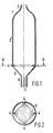
- Fig. 1 is a diagrammatic longitudinal section of a reactor according to the invention
- Fig. 2 is a cross-section along the line II-II in Fig. 1. Cooling and insulation, valves, thermometers, etc., are not shown in the drawings.
- a discharge 2 for synthesis gas and fly ash is provided in a top 1.
- passages 4 for fuel dust for example coal dust that has been pressurized in some known device and can be blown into the reactor with an inert gas, for example synthesis gas, steam or nitrogen.
- a bottom 5 is conical downward and becomes a slag discharge 6 in the centre of which an oxygen supply line 7 is located.
- the fuel passages 4 are located at regular intervals in the side wall 3.
- pour passages are drawn and the sprayers have an orifice angle of about 90°.
- the fuel dust is drawn as dots.
- coal dust had an average particle size of 50,um and had the following composition on a dry ashless basis:
- the ash content was 12.6% by weight and the moisture content was 2% by weight.
- the reactor had a pressure of 30 atm (2.94 10 6 Pa).
- a quantity of 33,500 kg/h of gas of 200°C and of the following composition was introduced through the supply line 7:
- the synthesis gas formed was practically free from soot and contained 3% by weight of fly ash which was separated off in a cyclone. The remaining solids were discharged as molten slag through 6 and dropped in a water bath to be cooled. The cooled slag-water mixture was drained through a lock system, the high pressure in the reactor being maintained.
Claims (3)
Applications Claiming Priority (2)
| Application Number | Priority Date | Filing Date | Title |
|---|---|---|---|
| NL8002989 | 1980-05-23 | ||
| NL8002989 | 1980-05-23 |
Publications (2)
| Publication Number | Publication Date |
|---|---|
| EP0040868A1 EP0040868A1 (de) | 1981-12-02 |
| EP0040868B1 true EP0040868B1 (de) | 1984-08-01 |
Family
ID=19835352
Family Applications (1)
| Application Number | Title | Priority Date | Filing Date |
|---|---|---|---|
| EP81200474A Expired EP0040868B1 (de) | 1980-05-23 | 1981-05-04 | Verfahren zur Herstellung von Synthesegas |
Country Status (5)
| Country | Link |
|---|---|
| EP (1) | EP0040868B1 (de) |
| AU (1) | AU541700B2 (de) |
| CA (1) | CA1173250A (de) |
| DE (1) | DE3165192D1 (de) |
| ZA (1) | ZA813409B (de) |
Families Citing this family (1)
| Publication number | Priority date | Publication date | Assignee | Title |
|---|---|---|---|---|
| CN1010028B (zh) * | 1985-05-29 | 1990-10-17 | 国际壳牌研究有限公司 | 褐煤气化器 |
Citations (1)
| Publication number | Priority date | Publication date | Assignee | Title |
|---|---|---|---|---|
| US541376A (en) * | 1895-06-18 | Box-trimming machine |
Family Cites Families (4)
| Publication number | Priority date | Publication date | Assignee | Title |
|---|---|---|---|---|
| LU29330A1 (de) * | ||||
| DE880623C (de) * | 1951-04-10 | 1953-06-22 | Hans Schmalfeldt | Verfahren und Vorrichtung zum Vergasen von Kohlenstaub |
| US3981690A (en) * | 1975-01-15 | 1976-09-21 | The United States Of America As Represented By The United States Energy Research And Development Administration | Agglomerating combustor-gasifier method and apparatus for coal gasification |
| US4200495A (en) * | 1978-09-18 | 1980-04-29 | Barry Liss | Prevention of defluidization in the treatment of caking carbonaceous solids |
-
1981
- 1981-03-24 CA CA000375158A patent/CA1173250A/en not_active Expired
- 1981-05-04 EP EP81200474A patent/EP0040868B1/de not_active Expired
- 1981-05-04 DE DE8181200474T patent/DE3165192D1/de not_active Expired
- 1981-05-21 ZA ZA00813409A patent/ZA813409B/xx unknown
- 1981-05-21 AU AU70903/81A patent/AU541700B2/en not_active Ceased
Patent Citations (1)
| Publication number | Priority date | Publication date | Assignee | Title |
|---|---|---|---|---|
| US541376A (en) * | 1895-06-18 | Box-trimming machine |
Also Published As
| Publication number | Publication date |
|---|---|
| ZA813409B (en) | 1982-06-30 |
| CA1173250A (en) | 1984-08-28 |
| DE3165192D1 (en) | 1984-09-06 |
| AU7090381A (en) | 1981-11-26 |
| AU541700B2 (en) | 1985-01-17 |
| EP0040868A1 (de) | 1981-12-02 |
Similar Documents
| Publication | Publication Date | Title |
|---|---|---|
| US4969930A (en) | Process for gasifying or combusting solid carbonaceous material | |
| AU2011336788B2 (en) | Method and apparatus for particle recycling in multiphase chemical reactors | |
| US4441892A (en) | Process for the gasification of carboniferous material in solid, pulverulent or even lump form | |
| US4145274A (en) | Pyrolysis with staged recovery | |
| US3981690A (en) | Agglomerating combustor-gasifier method and apparatus for coal gasification | |
| JPH0143799B2 (de) | ||
| CN1051055A (zh) | 两段煤气化工艺方法 | |
| US3454383A (en) | Gasification method and apparatus | |
| JP2001521056A (ja) | 固形燃料から燃焼ガス、合成ガス、還元ガスを生ぜしめるための方法および装置 | |
| JPH0631345B2 (ja) | 固体炭素質材料をガス化もしくは燃焼させる方法及び装置 | |
| US3957458A (en) | Gasifying coal or coke and discharging slag frit | |
| US2644745A (en) | Production of gases from carbonaceous solids | |
| EA017334B1 (ru) | Способ и установка для газификации твёрдого топлива в потоке под давлением | |
| JPH0324195A (ja) | 石炭ガス化反応器 | |
| CN101845326B (zh) | 旋流式熔融池气化炉 | |
| US4013427A (en) | Slag bath generator | |
| CA1154965A (en) | Method and apparatus for the gasification of coal | |
| WO1986001821A1 (en) | Gasification apparatus | |
| CA1076360A (en) | Method and apparatus for continuous gasification, of solid and/or fluid carbon-containing and/or hydro-carbon-containing substances in molten iron in a reaction vessel | |
| EP0150533B1 (de) | Verfahren und Vorrichtung zur Herstellung von Synthesegas | |
| JPS62236892A (ja) | 石炭のガス化方法及び装置 | |
| US4865626A (en) | Process for producing gas containing CO and H2 | |
| KR20010072468A (ko) | 용융 선철을 제조하는 방법 | |
| US4323366A (en) | Apparatus for the gasification of coal | |
| EP0040868B1 (de) | Verfahren zur Herstellung von Synthesegas |
Legal Events
| Date | Code | Title | Description |
|---|---|---|---|
| PUAI | Public reference made under article 153(3) epc to a published international application that has entered the european phase |
Free format text: ORIGINAL CODE: 0009012 |
|
| AK | Designated contracting states |
Designated state(s): DE GB NL |
|
| 17P | Request for examination filed |
Effective date: 19820125 |
|
| GRAA | (expected) grant |
Free format text: ORIGINAL CODE: 0009210 |
|
| AK | Designated contracting states |
Designated state(s): DE GB NL |
|
| REF | Corresponds to: |
Ref document number: 3165192 Country of ref document: DE Date of ref document: 19840906 |
|
| PGFP | Annual fee paid to national office [announced via postgrant information from national office to epo] |
Ref country code: NL Payment date: 19850531 Year of fee payment: 5 |
|
| PLBE | No opposition filed within time limit |
Free format text: ORIGINAL CODE: 0009261 |
|
| STAA | Information on the status of an ep patent application or granted ep patent |
Free format text: STATUS: NO OPPOSITION FILED WITHIN TIME LIMIT |
|
| 26N | No opposition filed | ||
| PG25 | Lapsed in a contracting state [announced via postgrant information from national office to epo] |
Ref country code: NL Effective date: 19861201 |
|
| NLV4 | Nl: lapsed or anulled due to non-payment of the annual fee | ||
| GBPC | Gb: european patent ceased through non-payment of renewal fee | ||
| PG25 | Lapsed in a contracting state [announced via postgrant information from national office to epo] |
Ref country code: DE Effective date: 19870203 |
|
| PG25 | Lapsed in a contracting state [announced via postgrant information from national office to epo] |
Ref country code: GB Effective date: 19881118 |