EP0040781B1 - Disconnecting switch for high-voltage metal-enclosed switchgear - Google Patents
Disconnecting switch for high-voltage metal-enclosed switchgear Download PDFInfo
- Publication number
- EP0040781B1 EP0040781B1 EP19810103784 EP81103784A EP0040781B1 EP 0040781 B1 EP0040781 B1 EP 0040781B1 EP 19810103784 EP19810103784 EP 19810103784 EP 81103784 A EP81103784 A EP 81103784A EP 0040781 B1 EP0040781 B1 EP 0040781B1
- Authority
- EP
- European Patent Office
- Prior art keywords
- contact
- tip
- diameter
- disconnecting switch
- hemispheric
- Prior art date
- Legal status (The legal status is an assumption and is not a legal conclusion. Google has not performed a legal analysis and makes no representation as to the accuracy of the status listed.)
- Expired
Links
Images

Classifications
-
- H—ELECTRICITY
- H01—ELECTRIC ELEMENTS
- H01H—ELECTRIC SWITCHES; RELAYS; SELECTORS; EMERGENCY PROTECTIVE DEVICES
- H01H33/00—High-tension or heavy-current switches with arc-extinguishing or arc-preventing means
- H01H33/02—Details
- H01H33/24—Means for preventing discharge to non-current-carrying parts, e.g. using corona ring
Definitions
- the invention relates to a high voltage shielded substation disconnector in a coaxial metal casing filled with compressed dielectric gas, said disconnector comprising a movable contact, cooperating with a fixed contact, said contacts being each carried by a fixed tubular contact holder coaxial with the 'envelope, the opposite ends of the contact carriers being each provided with a substantially hemispherical corona hood having a re-entrant cylindrical neck intended for the passage of the associated contact, said movable contact having a hemispherical tip.
- Patent CH-A-399,569 illustrates a known embodiment of contacts with hemispherical tips.
- a disconnector only cuts and establishes very low currents, generally capacitive currents corresponding to the capacitance of a busbar under voltage.
- a pre-ignition cut-off arc arises. This arc will tend to move under the action of the electric field at the periphery of the corona hoods, then the root of the arc may jump on the metal casing located at a short distance.
- the hailing arc due to the capacitive current then degenerates into a power arc, an earth fault arc, inside the envelope.
- the object of the invention is to provide a slow-action disconnector, in which the fixed and movable contacts and the corona shields have a shape such that the length of the arc is small, the electric field in the vicinity of the axis of the contacts. is also weak and that the arc from its birth and during its development remains in the zone with weak field in the vicinity of the axis.
- the subject of the invention is a disconnector for a shielded substation in a coaxial metal casing filled with compressed dielectric gas, said disconnector comprising a movable contact, cooperating with a fixed contact, said contacts being each carried by a fixed tubular contact carrier coaxial with the casing , the opposite ends of the contact carriers being provided with a substantially hemispherical corona hood having a re-entrant cylindrical neck intended for the passage of the movable contact, said movable contact having a hemispherical tip, the fixed contact comprising a moving contact piece limited to hemispherical tip of the same diameter as that of the tip of the movable contact, characterized in that in the open position, the end of the tip of the contact piece is preferably of limited movement disposed between the threshold inlet of the fume hood and the end of the inscription circle of its hemispherical part.
- the tip of the movable contact being disposed set back from the entry threshold of the cylindrical neck of the corona hood, the distance separating the thresholds of the corona hoods is between 50% and 100% of the diameter of the hemispherical parts.
- the diameter of the cylindrical necks is preferably between 20% and 35% of the diameter of the hemispherical parts.
- FIG. 1 there is shown a portion of an armored substation, made up of tubular metallic envelopes 1, the ends of which have connection flanges 2, between which are insulated isolators 3 which support active parts of the installation arranged coaxially.
- the tubular casings 1 are filled with a dielectric gas such as sulfur hexafluoride under a pressure of three to five bars.
- the envelopes 1 contain the constituent elements of a disconnector, the movable part of which is arranged on the right and the fixed part is arranged on the left.
- the movable part of the disconnector comprises a tubular movable contact 8, coaxial with the casing 1, the visible end of which comprises a hemispherical end piece 9.
- the axial movement of the movable contact 8 is controlled by means of a mechanism not shown under operator dependence.
- the movable contact 8 is placed inside a tubular contact carrier 4 supported by the insulator 3.
- the movable contact 8 is connected to the contact carrier 4 by means of sliding contacts 46 arranged in circular grooves 45 formed inside the contact holder 4.
- a corona hood 7 is disposed between the insulator 3 and the end of the contact holder 4 surrounding the nozzle 9.
- the cover 7 comprises a hemispherical part 70 connecting an envelope cylindrical 71 to a cylindrical neck 72 returning inwards, the cylindrical parts comprise a generator parallel to the axis of the disconnector.
- the fixed part of the disconnector comprises a contact piece with tubular limited movement 13 coaxial with the casing 1, one end of which comprises a hemispherical end piece 14 disposed opposite the end piece 9.
- the part 13 has a collar 15 on its other end subjected to a fixed compression spring 16 which tends to press it against a ring 17 forming a stop.
- a tubular contact carrier 10, disposed around the contact piece 13 and coaxial with the casing 1, is supported by an insulator similar to the insulator 3, not shown in the figure.
- the spring 16 is secured inside the contact carrier 10 which supports on the opposite side a ring of contact fingers 12 capable of cooperating with the contact member with limited movement 13 slidingly arranged along the ring 17.
- a protective cover -effluvia 6 similar to the cover 7 is disposed at the end of the contact carrier 10 and opposite the cover 7.
- the cover 6 thus comprises a hemispherical part 60 connecting a cylindrical envelope 61 to a cylindrical neck 62 returning inwards, the cylindrical parts comprising a generator parallel to the axis of the disconnector.
- the diameters of the cylindrical parts 61 to 71 on the one hand and 62 and 72 on the other hand are equal, while the radii of curvature of the hemispherical parts 60 and 70 are the same.
- the end of the hemispherical end piece 9 of the movable contact 8 is disposed slightly below the entry threshold 73 of the cylindrical neck 72.
- the end of the hemispherical end piece 14 is arranged substantially midway between the entry threshold 63 of the cylindrical neck 62 and what would constitute the end 64 of the sphere of inscription of the hemispherical part 60.
- the movable contact 8 and the end piece 9 are moved from right to left.
- the end piece 9 takes in particular the intermediate position traced in dashes and identified at 59 in this position; the distance between the cover 6 and the end piece 59 is short and a hail arc 20 erupts between these elements.
- the electric field deformed in the vicinity of the end pieces 59 and 14 is represented by the equipotential lines 23 drawn by dashes, in the upper part of FIG. 1.
- the arc 20 remaining substantially parallel to the equipotential lines does not tend to move . They go out when the ferrules 9 and 14 come into galvanic contact.
- the diameter of the hemispherical ends 9 and 14 and of the tubular contacts 8 and 13 is between 20 and 35% of the diameter of the cylindrical parts 71 and 61 of the covers 7 and 6.
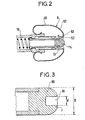
- FIG. 2 there is shown an alternative embodiment of the covers which still gives good results.
- the entry threshold 63 of the cylindrical neck 62 has a flat transverse range, the right end of the cover 6 representing a flat part with a diameter, the outside diameter does not exceed half the diameter of the cylindrical part 61.
- the contact end piece may have a blind hole.
- This arrangement can interest both the end piece 9 and the end piece 14.
- FIG. 3 represents such a end piece 80 comprising a blind hole 81; the edges of the hole are rounded, this allows the arc to be centered, forcing it to hang on the end of the end piece (rounded end of the hole).
- the dimensions of the hole are as follows for the best result: diameter of the hole d between 10 and 30% of the maximum diameter D of the nozzle 80, radius r of the rounding at the end of the hole between 20 and 50% of the hole diameter.
Description
L'invention concerne un sectionneur de poste blindé à haute tension sous enveloppe métallique coaxiale remplie de gaz diélectrique comprimé, ledit sectionneur comprenant un contact mobile, coopérant avec un contact fixe, lesdits contacts étant portés chacun par un porte-contact tubulaire fixe coaxial avec l'enveloppe, les extrémités en regard des porte-contact étant munies chacune d'un capot pare-effluves sensiblement hémisphérique présentant un col cylindrique rentrant destiné au passage du contact associé, ledit contact mobile présentant un embout hémisphérique.The invention relates to a high voltage shielded substation disconnector in a coaxial metal casing filled with compressed dielectric gas, said disconnector comprising a movable contact, cooperating with a fixed contact, said contacts being each carried by a fixed tubular contact holder coaxial with the 'envelope, the opposite ends of the contact carriers being each provided with a substantially hemispherical corona hood having a re-entrant cylindrical neck intended for the passage of the associated contact, said movable contact having a hemispherical tip.
Le brevet CH-A-399 569 illustre un mode connu de réalisation de contacts à embouts hémisphériques.Patent CH-A-399,569 illustrates a known embodiment of contacts with hemispherical tips.
Un sectionneur ne coupe et n'établit que des courants très faibles, généralement des courants capacitifs correspondant à la capacitance d'un jeu de barres sous tension.A disconnector only cuts and establishes very low currents, generally capacitive currents corresponding to the capacitance of a busbar under voltage.
S'agissant d'un sectionneur disposé à l'air libre, à l'intérieur d'un bâtiment ou à l'extérieur, la coupure d'un tel courant et son établissement ne causent que des effets négligeables, les distances entre pièces sous tension et les charpentes ou parois mises à la terre étant grandes. Mais pour les postes blindés sous enveloppe métallique remplie de gaz isolant, tels qu'ils sont utilisés pour des tensions atteignant 800 kV, ies-distances sont courtes et les gradients de tension sont élevés.In the case of a disconnector placed in the open air, inside a building or outside, the interruption of such a current and its establishment only cause negligible effects, the distances between rooms under tension and the earthed frames or walls being large. However, for shielded substations in a metal envelope filled with insulating gas, as they are used for voltages up to 800 kV, the distances are short and the voltage gradients are high.
Pour avoir les distances minimales, la distribution du champ électrique doit être homogène; on utilise aussi les capots mis sous tension qui élèvent le seuil de tension de l'apparition d'effluves. De tels capots présentent souvent entre entrée et sortie du sectionneur une partie plate perpendiculaire à l'axe du sectionneur, associée par des arrondis à une partie cylindrique très lisse, dont l'axe se confond avec l'axe du sectionneur.To have the minimum distances, the distribution of the electric field must be homogeneous; we also use energized hoods which raise the voltage threshold for the appearance of aromas. Such covers often have a flat part between the input and output of the disconnector perpendicular to the axis of the disconnector, associated by rounding with a very smooth cylindrical part, the axis of which merges with the axis of the disconnector.
Lors des manoeuvres d'ouverture et de fermeture d'un sectionneur, à vitesse de manoeuvre lente, un arc de coupure d'abord de préamorçage prend naissance. Cet arc aura tendance à se déplacer sous l'action du champ électrique à la périphérie des capots pare-effluves, puis la racine de l'arc peut sauter sur l'enveloppe métallique située à courte distance. L'arc grèle dû au courant capacitif dégénère alors en arc de puissance, arc de défaut à la terre, à l'intérieur de l'enveloppe.During the opening and closing operations of a disconnector, at a slow operating speed, a pre-ignition cut-off arc arises. This arc will tend to move under the action of the electric field at the periphery of the corona hoods, then the root of the arc may jump on the metal casing located at a short distance. The hailing arc due to the capacitive current then degenerates into a power arc, an earth fault arc, inside the envelope.
Il est connu par le document DE-A 27 04 385 de placer un écran métallique sous tension autour du contact fixe et à une distance radiale supérieure à la distance de préamorçage. L'arc de préamorçage ou de coupure est alors piégé par l'écran, il ne peut s'étendre jusqu'à l'enveloppe, mais ceci augmente la course du sectionneur.It is known from document DE-A 27 04 385 to place a metallic screen under tension around the fixed contact and at a radial distance greater than the pre-priming distance. The pre-strike or cut-off arc is then trapped by the screen, it cannot extend to the enclosure, but this increases the stroke of the disconnector.
Il est aussi connu d'utiliser un mécanisme à ouverture et fermeture brusques qui, réduisant considérablement la durée de l'arc, empêche ce dernier de se développer de façon erratique. Un tel dispositif, généralement adopté pour les interrupteurs est très onéreux pour le sectionneur.It is also known to use an abrupt opening and closing mechanism which, considerably reducing the duration of the arc, prevents the arc from developing erratically. Such a device, generally adopted for switches, is very expensive for the disconnector.
L'invention a pour but un sectionneur à manoeuvre lente, dans lequel les contacts fixes et mobiles et les capots pare-effluves ont une forme telle que la longueur de l'arc soit faible, le champ électrique au voisinage de l'axe des contacts soit faible aussi et que l'arc dès sa naissance et au cours de son développement reste dans la zone à faible champ au voisinage de l'axe.The object of the invention is to provide a slow-action disconnector, in which the fixed and movable contacts and the corona shields have a shape such that the length of the arc is small, the electric field in the vicinity of the axis of the contacts. is also weak and that the arc from its birth and during its development remains in the zone with weak field in the vicinity of the axis.
L'invention a pour objet un sectionneur pour poste blindé sous enveloppe métallique coaxiale remplie de gaz diélectrique comprimé, ledit sectionneur comprenant un contact mobile, coopérant avec un contact fixe lesdits contacts étant portés chacun par un porte-contact tubulaire fixe coaxial avec l'enveloppe, les extrémités en regard des porte-contact étant munies d'un capot pare-effluves sensiblement hémisphérique présentant un col cylindrique rentrant destiné au passage du contact mobile, ledit contact mobile présentant un embout hémisphérique, le contact fixe comprenant une pièce de contact à mouvement limité à embout hémisphérique de même diamètre que celui de l'embout du contact mobile, caractérisé en ce qu'en position d'ouverture, l'extrémité de l'embout de la pièce de contact est de préférence à mouvement limité disposée entre le seuil d'entrée du capot pare-effluves et l'extrémité du cercle d'inscription de sa partie hémisphérique.The subject of the invention is a disconnector for a shielded substation in a coaxial metal casing filled with compressed dielectric gas, said disconnector comprising a movable contact, cooperating with a fixed contact, said contacts being each carried by a fixed tubular contact carrier coaxial with the casing , the opposite ends of the contact carriers being provided with a substantially hemispherical corona hood having a re-entrant cylindrical neck intended for the passage of the movable contact, said movable contact having a hemispherical tip, the fixed contact comprising a moving contact piece limited to hemispherical tip of the same diameter as that of the tip of the movable contact, characterized in that in the open position, the end of the tip of the contact piece is preferably of limited movement disposed between the threshold inlet of the fume hood and the end of the inscription circle of its hemispherical part.
Selon une mise en oeuvre préférée de l'invention, l'embout du contact mobile étant disposé en retrait du seuil d'entrée du col cylindrique du capot pare-effluves, la distance séparant les seuils des capots pare-effluves est comprise entre 50% et 100% du diamètre des parties hémisphériques. Le diamètre des cols cylindriques est de préférence compris entre 20% et 35% du diamètre des parties hémisphériques.According to a preferred implementation of the invention, the tip of the movable contact being disposed set back from the entry threshold of the cylindrical neck of the corona hood, the distance separating the thresholds of the corona hoods is between 50% and 100% of the diameter of the hemispherical parts. The diameter of the cylindrical necks is preferably between 20% and 35% of the diameter of the hemispherical parts.
L'invention sera décrite ci-après plus en détail à l'aide des figures ci-annexées.
- La figure 1 représente une vue schématique partielle et en coupe axiale d'un sectionneur de poste blindé selon l'invention.
- La figure 2 représente une vue schématique en coupe axiale d'une variante de capot pare-effluves d'un sectionneur selon l'invention.
- La figure 3 représente une vue en coupe agrandie d'une variante d'un embout de contact.
- FIG. 1 represents a partial schematic view in axial section of an armored substation disconnector according to the invention.
- FIG. 2 represents a schematic view in axial section of a variant of the corona hood of a disconnector according to the invention.
- Figure 3 shows an enlarged sectional view of a variant of a contact tip.
Dans la figure 1 on a représenté une portion de poste blindé, constitué à l'aide d'enveloppes métalliques tubulaires 1, dont les extrémités comportent des brides de raccordement 2, entre lesquelles sont serrés des isolateurs 3 qui supportent des parties actives de l'installation disposées coaxialement. Les enveloppes tubulaires 1 sont remplies d'un gaz diélectrique tel que de l'hexafluorure de soufre sous une pression de trois à cinq bars.In Figure 1 there is shown a portion of an armored substation, made up of tubular metallic envelopes 1, the ends of which have
Les enveloppes 1 contiennent les éléments constitutifs d'un sectionneur dont la partie mobile est disposée à droite et la partie fixe est disposée à gauche.The envelopes 1 contain the constituent elements of a disconnector, the movable part of which is arranged on the right and the fixed part is arranged on the left.
La partie mobile du sectionneur comprend un contact mobile tubulaire 8, coaxial avec l'enveloppe 1, dont l'extrémité visible comporte un embout hémisphérique 9. Le déplacement axial du contact mobile 8 est commandé par l'intermédiaire d'un mécanisme non représenté sous la dépendance d'un opérateur. Le contact mobile 8 est placé à l'intérieur d'un porte-contact 4 tubulaire supporté par l'isolateur 3. Le contact mobile 8 est relié au porte-contact 4 par l'intermédiaire de contacts glissants 46 disposés dans des rainures circulaires 45 ménagées à l'intérieur du porte-contact 4. Un capot pare-effluves 7 est disposé entre l'isolateur 3 et l'extrémité du porte-contact 4 entourant l'embour 9. Le capot 7 comporte une partie hémisphérique 70 reliant une enveloppe cylindrique 71 à un col cylindrique 72 rentrant vers l'intérieur, les parties cylindriques comportent une génératrice parallèle à l'axe du sectionneur.The movable part of the disconnector comprises a tubular
La partie fixe du sectionneur comprend une pièce de contact à mouvement limité tubulaire 13 coaxial avec l'enveloppe 1, dont une extrémité comporte un embout hémisphérique 14 disposé en regard de l'embout 9. La pièce 13 comporte sur son autre extrémité un collet 15 soumis à un ressort de compression fixe 16 qui a tendance à l'appuyer contre une bague 17 formant butée. Un porte-contact 10 tubulaire, disposé autour de la pièce de contact 13 et coaxial avec l'enveloppe 1, est supporté par un isolateur similaire à l'isolateur 3, non représenté dans la figure. Le ressort 16 est assujetti à l'intérieur du porte-contact 10 qui supporte du côté opposé une couronne de doigts de contact 12 susceptible de coopérer avec la pièce de contact à mouvement limité 13 disposée coulissante le long de la bague 17. Un capot pare-effluves 6 analogue au capot 7 est disposé à l'extrémité du porte-contact 10 et en regard du capot 7. Le capot 6 comporte ainsi une partie hémisphérique 60 reliant une enveloppe cylindrique 61 à un col cylindrique 62 rentrant vers l'intérieur, les parties cylindriques comportant une génératrice parallèle à l'axe du sectionneur. Les diamètres des parties cylindriques 61 à 71 d'une part et 62 et 72 d'autre part sont égaux, tandis que les rayons de courbure des parties hémisphériques 60 et 70 sont les mêmes.The fixed part of the disconnector comprises a contact piece with tubular
En position d'ouverture représentée en figure 1, l'extrémité de l'embout hémisphérique 9 du contact mobile 8 est disposé légèrement en retait du seuil 73 d'entrée du col cylindrique 72. Par contre l'extrémité de l'embout hémisphérique 14 est disposée sensiblement à mi- distance entre le seuil d'entrée 63 du col cylindrique 62 et ce qui constituerait l'extrémité 64 de la sphère d'inscription de la partie hémisphérique 60.In the open position shown in FIG. 1, the end of the
Lors de la fermeture du sectionneur, le contact mobile 8 et l'embout 9 sont déplacés de droite à gauche. L'embout 9 prend en particulier la position intermédiaire tracée en tirets et repérée en 59 dans cette position; la distance entre le capot 6 et l'embout 59 est courte et un arc grèle 20 jaillit entre ces éléments. Le champ électriques déformé au voisinage des embouts 59 et 14 est représenté par les lignes équipotentielles 23 tracées par des tirets, à la partie supérieure de la figure 1. L'arc 20 restant sensiblement parallèle aux lignes équipotentielles n'a pas tendance à se déplacer. Ils s'éteint lors de l'entrée en contact galvanique des embouts 9 et 14. Quand le sectionneur a terminé sa course, le contact s'établit entre les doigts de contact 12 et le contact mobile 8, qui a le même diamètre que le contact à mouvement limité 13 et qui est repoussé contre l'action du ressort 16; son embout 14 prend la position repérée en 54 et l'embout est alors en 69.When the disconnector is closed, the
Dans ces conditions, on obtient dans l'intervalle entre les capots 7 et 6 un champ électrique dont les lignes équipotentielles 22, sensiblement symétriques sont matérialisées par des tirets à la partie inférieure de la figure 1.Under these conditions, an electric field is obtained in the interval between the covers 7 and 6, the substantially symmetrical
Lors de l'ouverture du sectionner, le déplacement du contact mobile 8 de gauche à droite entraîne le même mouvement de gauche à droite de la pièce de contact à mouvement limité 13 sous l'action du ressort 16 jusqu'à ce que le collet 15 vienne buter contre la bague 17. Après séparation galvanique des embouts 9 et 14 un arc prend naissance entre ces embouts, l'arc étant dans une zone à faible gradient reste rectiligne et se déplace au maximum sur l'extrémité droite du capot 6. La forme sphérique du capot 6 empêche le déplacement de l'arc vers la partie cylindrique 60 et vers l'enveloppe 1. Le courant a une très faible valeur, inférieure à un ampère, et l'arc s'éteint de lui-même dans le gaz diélectrique d'hexafluorure de soufre quand la distance entre les embouts 9 et 14 est suffisante. On obtient de bons résultats quand la distance d'ouverture séparant les capots 7 et l'embout 9 est comprise entre 50% et 100% du diamètre des enveloppes cylindriques 71 et 61, la valeur optimale étant voisine de 75%.When opening the section, the movement of the
Le diamètre des embouts hémisphériques 9 et 14 et des contacts tubulaires 8 et 13 est compris entre 20 et 35% du diamètre des parties cylindriques 71 et 61 des capots 7 et 6.The diameter of the
Dans la figure 2 on a représenté une variante de réalisation des capots qui donne encore de bons résultats. Le seuil 63 d'entrée du col cylindrique 62 comporte une plage transversale plate dont l'extrémité droit du capot 6 représente une partie plate d'un diamètre, le diamètre extérieur ne dépasse par la moitié du diamètre de la partie cylindrique 61.In Figure 2 there is shown an alternative embodiment of the covers which still gives good results. The
Dans une autre variant l'embout de contact peut présenter un trou borgne. Cette disposition peut intéresser aussi bien l'embout 9 que l'embout 14. La figure 3 représente un tel embout 80 comportant un trou borgne 81; les bords du trou sont arrondis, ceci permet de centrer l'arc, en le forçant à s'accrocher sur l'extrémité de l'embout (extrémité arrondie du trou). Les dimensions du trou sont les suivantes pour le meilleur résultat: diamètre du trou d entre 10 et 30% du diamètre maximal D de l'embout 80, rayon r de l'arrondi à l'extrémité du trou compris entre 20 et 50% du diamètre du trou.In another variant, the contact end piece may have a blind hole. This arrangement can interest both the
Claims (3)
Applications Claiming Priority (2)
| Application Number | Priority Date | Filing Date | Title |
|---|---|---|---|
| FR8011510A FR2483121A1 (en) | 1980-05-23 | 1980-05-23 | HIGH VOLTAGE SHUTTER POST DISCONNECT |
| FR8011510 | 1980-05-23 |
Publications (2)
| Publication Number | Publication Date |
|---|---|
| EP0040781A1 EP0040781A1 (en) | 1981-12-02 |
| EP0040781B1 true EP0040781B1 (en) | 1984-09-19 |
Family
ID=9242268
Family Applications (1)
| Application Number | Title | Priority Date | Filing Date |
|---|---|---|---|
| EP19810103784 Expired EP0040781B1 (en) | 1980-05-23 | 1981-05-18 | Disconnecting switch for high-voltage metal-enclosed switchgear |
Country Status (4)
| Country | Link |
|---|---|
| EP (1) | EP0040781B1 (en) |
| CA (1) | CA1174717A (en) |
| DE (1) | DE3166132D1 (en) |
| FR (1) | FR2483121A1 (en) |
Families Citing this family (9)
| Publication number | Priority date | Publication date | Assignee | Title |
|---|---|---|---|---|
| CH658936A5 (en) * | 1982-08-26 | 1986-12-15 | Bbc Brown Boveri & Cie | METAL-ENCLOSED HIGH VOLTAGE SWITCHGEAR. |
| FR2558300B1 (en) * | 1984-01-17 | 1986-10-10 | Merlin Gerin | DISCONNECTOR FOR HIGH-VOLTAGE SHIELDED STATION |
| FR2558301B1 (en) * | 1984-01-17 | 1986-10-10 | Merlin Gerin | HIGH VOLTAGE SHIELDED STATION SWITCH EQUIPPED WITH PERFORATED SPRAY SCREENS |
| FR2592210B1 (en) * | 1985-12-20 | 1990-07-27 | Merlin Gerin | ISOLATION DISCONNECTOR OF A HIGH VOLTAGE SHIELDED INSTALLATION |
| DE4103119A1 (en) * | 1991-01-31 | 1992-08-06 | Siemens Ag | EXHAUST GAS SWITCH |
| DE4210545A1 (en) * | 1992-03-31 | 1993-10-07 | Asea Brown Boveri | Breaker switch for metal-encapsulated HV switch appts. - has pair of cooperating movable and stationary contact pieces within switch encapsulation, each having pre-ignition contact pin |
| FR2758916B1 (en) * | 1997-01-30 | 1999-04-02 | Gec Alsthom T & D Sa | FIREPLACE HOOD |
| EP2696361B1 (en) * | 2012-08-09 | 2017-03-29 | ABB Schweiz AG | Gas-insulated disconnector with shield |
| FR3002364B1 (en) * | 2013-02-20 | 2016-08-19 | Alstom Technology Ltd | ELECTRICAL EQUIPMENT COMPRISING A MOBILE ELECTRODE |
Family Cites Families (8)
| Publication number | Priority date | Publication date | Assignee | Title |
|---|---|---|---|---|
| US2196008A (en) * | 1937-07-06 | 1940-04-02 | Gen Electric | Shielded contact construction for circuit breakers |
| CA572848A (en) * | 1954-10-04 | 1959-03-24 | H. Rugg Harold | Disconnecting switch |
| FR83183E (en) * | 1962-11-30 | 1964-06-26 | Comp Generale Electricite | High voltage shielded cubicles with disconnecting device |
| DE1540513A1 (en) * | 1965-08-19 | 1970-01-08 | Siemens Ag | Compressed gas insulated high-voltage switchgear |
| US3356798A (en) * | 1965-12-13 | 1967-12-05 | Westinghouse Electric Corp | Disconnect switch |
| US4029923A (en) * | 1976-01-15 | 1977-06-14 | Westinghouse Electric Corporation | Magnetizing current switch |
| US4107498A (en) * | 1976-01-15 | 1978-08-15 | Westinghouse Electric Corp. | Disconnect switch and drive mechanism therefor |
| FR2344987A1 (en) * | 1976-03-15 | 1977-10-14 | Merlin Gerin | EARTHING SWITCH FOR HIGH VOLTAGE SHIELDED SUBSTATION |
-
1980
- 1980-05-23 FR FR8011510A patent/FR2483121A1/en active Granted
-
1981
- 1981-05-18 EP EP19810103784 patent/EP0040781B1/en not_active Expired
- 1981-05-18 DE DE8181103784T patent/DE3166132D1/en not_active Expired
- 1981-05-22 CA CA000378145A patent/CA1174717A/en not_active Expired
Also Published As
| Publication number | Publication date |
|---|---|
| DE3166132D1 (en) | 1984-10-25 |
| FR2483121B1 (en) | 1982-12-17 |
| CA1174717A (en) | 1984-09-18 |
| EP0040781A1 (en) | 1981-12-02 |
| FR2483121A1 (en) | 1981-11-27 |
Similar Documents
| Publication | Publication Date | Title |
|---|---|---|
| EP0388323B1 (en) | Autoexpansion electric circuit breaker with insulating gas | |
| EP0385886B1 (en) | Circuit breaker with a rotating arc and with a centrifugal effect of the extinguishing gas | |
| EP0543681B1 (en) | Middle voltage circuit breaker for inside or outside | |
| EP0040781B1 (en) | Disconnecting switch for high-voltage metal-enclosed switchgear | |
| CH634949A5 (en) | DEVICE FOR INSERTING A RESISTANCE TO THE ONLY CLOSING OF AN INTERRUPTION APPARATUS. | |
| CA2053951C (en) | Integrated capacitor sf6 circuit-breaker | |
| FR2491675A1 (en) | Gas blast type high voltage circuit breaker - has operating piston moving contact ring axially into set of contacts held on hemispherical support | |
| CA2095896C (en) | Perpendicularly opening grounding switch | |
| FR2512267A1 (en) | COMPRESSED GAS CIRCUIT BREAKER WITH OPENING AND CLOSING RESISTORS | |
| CA2206950C (en) | High-voltage switch with resistor insertion upon closing | |
| FR2576143A1 (en) | HIGH-VOLTAGE, COMPRESSED GAS, CIRCUIT BREAKER ASSISTED BY THE ARC THERMAL EFFECT AND WITH DOUBLE MOTION | |
| EP0759629B1 (en) | Circuit breaker with closing resistor and insertion device | |
| CA2117836C (en) | High voltage circuit breaker for interrupting fault current by delayed zero crossing | |
| FR2814275A1 (en) | GAS INSULATED CIRCUIT BREAKER WITH AN INTEGRATED ELECTRONIC CURRENT TRANSFORMER | |
| EP0398213B1 (en) | Middle high-voltage circuit breaker for high nominal current | |
| EP0236641B1 (en) | Isolator for a metal-clad high tension installation | |
| EP2633538A1 (en) | Electrical apparatus in a metal case said apparatus comprising at least one corona-shield cap ensuring convective exchange | |
| CH675651A5 (en) | High-tension circuit breaker with closing resistor | |
| EP1512160B1 (en) | High voltage shielded gear comprising a circuit breaker with closure resistor mounted in a conducting bar | |
| FR2558300A1 (en) | High-voltage shielded set isolator. | |
| CA1273043A (en) | Closing resistor dielectric gas high voltage circuit-breaker | |
| EP0823721B1 (en) | Self-blasting electrical circuit breaker with a rotating arc | |
| FR2737937A1 (en) | High tension circuit breaker with double movement within reduced volume | |
| US5198630A (en) | Resistance insertion type circuit-breaker | |
| FR2933806A1 (en) | ELECTRICAL DEVICE UNDER METAL ENVELOPE WITH REDUCED VOLTAGE GRADIENT. |
Legal Events
| Date | Code | Title | Description |
|---|---|---|---|
| PUAI | Public reference made under article 153(3) epc to a published international application that has entered the european phase |
Free format text: ORIGINAL CODE: 0009012 |
|
| AK | Designated contracting states |
Designated state(s): DE GB IT |
|
| 17P | Request for examination filed |
Effective date: 19820526 |
|
| ITF | It: translation for a ep patent filed |
Owner name: JACOBACCI & PERANI S.P.A. |
|
| GRAA | (expected) grant |
Free format text: ORIGINAL CODE: 0009210 |
|
| AK | Designated contracting states |
Designated state(s): DE GB IT |
|
| REF | Corresponds to: |
Ref document number: 3166132 Country of ref document: DE Date of ref document: 19841025 |
|
| PLBE | No opposition filed within time limit |
Free format text: ORIGINAL CODE: 0009261 |
|
| STAA | Information on the status of an ep patent application or granted ep patent |
Free format text: STATUS: NO OPPOSITION FILED WITHIN TIME LIMIT |
|
| 26N | No opposition filed | ||
| ITTA | It: last paid annual fee | ||
| PGFP | Annual fee paid to national office [announced via postgrant information from national office to epo] |
Ref country code: GB Payment date: 19940422 Year of fee payment: 14 |
|
| PGFP | Annual fee paid to national office [announced via postgrant information from national office to epo] |
Ref country code: DE Payment date: 19940526 Year of fee payment: 14 |
|
| PG25 | Lapsed in a contracting state [announced via postgrant information from national office to epo] |
Ref country code: GB Effective date: 19950518 |
|
| GBPC | Gb: european patent ceased through non-payment of renewal fee |
Effective date: 19950518 |
|
| PG25 | Lapsed in a contracting state [announced via postgrant information from national office to epo] |
Ref country code: DE Effective date: 19960201 |