EP0040549A1 - Engine - Google Patents
Engine Download PDFInfo
- Publication number
- EP0040549A1 EP0040549A1 EP81302237A EP81302237A EP0040549A1 EP 0040549 A1 EP0040549 A1 EP 0040549A1 EP 81302237 A EP81302237 A EP 81302237A EP 81302237 A EP81302237 A EP 81302237A EP 0040549 A1 EP0040549 A1 EP 0040549A1
- Authority
- EP
- European Patent Office
- Prior art keywords
- engine
- rocker arm
- pistons
- piston
- chambers
- Prior art date
- Legal status (The legal status is an assumption and is not a legal conclusion. Google has not performed a legal analysis and makes no representation as to the accuracy of the status listed.)
- Withdrawn
Links
Images


Classifications
-
- F—MECHANICAL ENGINEERING; LIGHTING; HEATING; WEAPONS; BLASTING
- F01—MACHINES OR ENGINES IN GENERAL; ENGINE PLANTS IN GENERAL; STEAM ENGINES
- F01C—ROTARY-PISTON OR OSCILLATING-PISTON MACHINES OR ENGINES
- F01C9/00—Oscillating-piston machines or engines
- F01C9/002—Oscillating-piston machines or engines the piston oscillating around a fixed axis
-
- F—MECHANICAL ENGINEERING; LIGHTING; HEATING; WEAPONS; BLASTING
- F02—COMBUSTION ENGINES; HOT-GAS OR COMBUSTION-PRODUCT ENGINE PLANTS
- F02B—INTERNAL-COMBUSTION PISTON ENGINES; COMBUSTION ENGINES IN GENERAL
- F02B75/00—Other engines
- F02B75/02—Engines characterised by their cycles, e.g. six-stroke
- F02B2075/022—Engines characterised by their cycles, e.g. six-stroke having less than six strokes per cycle
- F02B2075/025—Engines characterised by their cycles, e.g. six-stroke having less than six strokes per cycle two
-
- F—MECHANICAL ENGINEERING; LIGHTING; HEATING; WEAPONS; BLASTING
- F02—COMBUSTION ENGINES; HOT-GAS OR COMBUSTION-PRODUCT ENGINE PLANTS
- F02B—INTERNAL-COMBUSTION PISTON ENGINES; COMBUSTION ENGINES IN GENERAL
- F02B75/00—Other engines
- F02B75/02—Engines characterised by their cycles, e.g. six-stroke
- F02B2075/022—Engines characterised by their cycles, e.g. six-stroke having less than six strokes per cycle
- F02B2075/027—Engines characterised by their cycles, e.g. six-stroke having less than six strokes per cycle four
Definitions
- This invention relates to engines.
- the present invention provides a novel engine wherein the cylinder of the engine is configured as an annular cylinder having pairs of opposed pistons cooperating therein.
- the two pistons of each pair are interconnected by a curvilinear tie rod to one end of a rocker arm, there being two such intersecting rocker arms pivotally mounted about a common axis.
- the rocker arms are joined by a crank apparatus to the gear system for the engine for converting the oscillatory movement of the rocker arms into a rotary motion in the gears.
- the engine of the invention is suitable for (a) two-stroke, or four-stroke internal combustion engine operation, (b) two-stroke external combustion engine operation, or (c) in combination with a.compressor configuration.
- Pistons 25 and 27 are mounted to tie rod 18 joined to end 12b of rocker arm 12 while pistons.27 and 28 are mounted to the ends of tie rod 19 secured to end 14b of rocker arm 14.
- An annular cylinder 11 contains cylinder liners 36 - 39 so that coacting pairs of pistons form compression/ combustion chambers 31--34, respectively, therein.
- pistons 21 and 28 cooperate in cylinder liner 36 to form combustion/compression chamber 31.
- the same features are found for each of the remaining pistons 22 - 27, as will be clearly seen from each of Figures 1 - 4.
- each of compression/combustion chambers 31 - 34 are configured as internal combustion chambers having spark plugs 41 - 44, respectively, mounted therein.
- the_ reverse movement of each of pistons 21 - 28 is a power/expansion stroke wherein a fuel/air mixture is appropriately ignited and combusted in combustion chambers 31 - 34.
- each forward movement of pistons 21 - 28 in combination with the respective opposing piston serves as a compression stroke to compress a fuel/air mixture in the respective combustion chambers 31 - 34.
- Intake and exhaust ports are provided through the walls of annular cylinder chamber 11 and Irrespective cylinder liners 36 - 39 therein.
- intake ports 61 and 68 are provided for combustion chamber 3 1 while intake ports 62 and 63 provide intake for combustion chamber 32; intake ports 64 and 65 for combustion chamber 33; and intake ports 66 and 67 for combustion chamber 34.
- Each of intake ports 61 - 68 are selectively interconnected through intake plenum chambers 51 - 58, respectively, each of which is selectively connected to an intake header (not shown) by intake conduits 51a - 58a, respectively.
- each cfpistons 21 - 28 operates substantially identical to piston 21 in that reverse movement of piston 21 exposes intake port 61 thereby allowing an appropriate fuel/air mixture to be introduced from the intake header (not shown) through intake conduit 51a into intake plenum chamber 51 thence through intake port 61 into combustion chamber 31. Forward movement of piston 21 covers intake port 61 and commences the compression of the fuel/air mixture thus obtained.
- Exhaust from combustion chamber 31 is discharged through exhaust ports 71 and 78 into exhaust plenum chamber 61 and vented through exhaust conduit 61a into an exhaust header (not shown).
- Corresponding exhaust ports 72 and 73 discharge into exhaust plenum chamber 61 and through exhaust conduit 62a.
- Exhaust ports 74 and 75 discharge into exhaust plenum chamber 63 and exhaust conduit 63a.
- Exhaust ports 76 and 77 discharge into exhaust plenum chamber 64 and exhaust conduit 64a.
- a fuel/air mixture in combustion chamber 31 is ignited at an appropriate time by a spark produced by spark plug 41 with the resulting increase in pressure forcing apart pistons 21 and 28, thereby transmitting the appropriate power through cranks 48 and 49 to side gears 46 and 47, respectively, and ultimately into main gear 59.
- pistons 21 and 28 exposes exhaust ports 71 and 78, respectively, allowing the burned fuel/air mixture to be discharged from combustion chamber 31.
- intake ports 61 and 68 respectively, accommodating the inrush of a.fresh charge of fuel/air mixture with the initial portions of the fuel/air mixture assisting in purging the exhaust products through exhaust ports 71 and 78, respectively.
- novel two-cycle engine apparatus of this invention provides the additional advantage-in that the end of each power stroke of one set of pistons is balanced by the compression encountered by the opposing pistons, thereby cushioning the same and assisting in the reverse movement of each of the respective sets of pistons.
- a third preferred embodiment of the novel engine apparatus of this invention is shown generally at 30 and is configured as a four-cycle, internal combustion engine.
- each of combustion chambers 31 - 34 incorporates therein a set of intake valves 91 - 94 and a set of exhaust valves 95 98 respectively.
- Intake valves 91 - 94 and exhaust valves 95 - 98 are operated by the appropriate, conventional valve actuation systems (not shown) operated by a cam-driven valve lifter system (not shown).
- a specified valve system is shown for the novel engine apparatus of this invention, it should be clearly understood that any suitable valve system could be incorporated into the novel engine apparatus and method of this invention.
- a power cycle is commenced by the ignition of a fuel/air mixture in combustion chamber 31 by spark plug 41 igniting the fuel/air mixture with the resultant explosion, forcing apart pistons 21 and 28.
- exhaust valve 98 is opened, allowing the exhaust products to be discharged from combustion chamber 31.
- intake valve 91 is opened allowing a fresh fuel/air mixture to enter combustion chamber 31.
- intake valve 91 is closed so that as pistons 21 and 28 move toward each other, the fuel/air mixture in combustion chamber 31 is compressed.
- a spark as suitably timed for the speed of operation, etc., as is conventional, from spark plug 41 initiates combustion of the same, commencing the power stroke.
- the power thus generated is transmitted to rocker arms 12 and 14 and translated into rotary motion by cranks 48 and 49, respectively, and transmitted by side gears 46 and 47 to main gear 59.
- combustion chambers 31 and 33 While each of opposed combustion chamber pairs, combustion chambers 31 and 33, as opposed to combustion chambers 32 and 34, may be paired so as to both operate on the same intake, compression, expansion and exhaust cycles, the opposing combustion chambers and valve systems may be configured so as to be directly out of phase with the opposing combustion chamber.
- combustion chamber 31 While combustion chamber 31 is in the expansion/power stroke mode, combustion chamber 33 would be in the intake mode.. Simultaneously, combustion chamber 32 would be in the exhaust mode while combustion chamber 34 would be in the compression mode of operation. Accordingly, since there are four combustion chambers, combustion chambers 31 - 34, each combustion chamber would be selectively timed so as to fire sequentially, thereby substantially smoothing out the overall operation of four-cycle engine apparatus 30.
- a combination two-cycle, internal combustion engine/ compressor apparatus is shown generally at 40 and includes combustion chambers 31 and 33 on opposite sides thereof with compression chambers 32:and 34 in place of the previous internal combustion chambers.
- each of internal combustion chambers 31 and 33 is operated as conventional, two-cycle internal combustion engine apparatus involving the appropriate intake and exhaust ports and fuel ignition as set forth hereinbefore with respect to the two-cycle engine apparatus 20 shown in Figure 2.
- compression chambers 32 and 34 are configured as compressor chambers with intake valves 92 and 94 and exhaust valves 96 and 98. Accordingly, during a power stroke from each of combustion chambers 31 and 33, the corresponding pistons 22 and 23 compress a gaseous mixture in compression chamber 32 while corresponding pistons 26 and 27 compress the gaseous medium in compression chamber 34.
- exhaust valves 96 and 98 are opened, allowing the compressed air to be discharged into the high pressure system (not shown).
- exhaust valves 96 and 98 are closed while intake valves 92 and 94 are opened so that air is drawn into the particular compression chamber.
- Figure 4 embodiment may be modified so that the combustion chambers are separated by 90° rather than being diametrically opposite, for example chambers 3 1 and 34 are combustion chambers and each are provided with fuel ignition means and appropriate intake and exhaust ports.
- the compression chambers are then also separated by 90°, for example chambers 32 and 33, and are configured with similar intake valves and exhaust valves.
- Engine apparatus 10 is shown in perspective and is specifically configured for operations as a diesel engine in that fuel injection is provided through fuel injectors 101 - 104 into the appropriate combustion chambers.
- the valving system may be provided either as a two-cycle engine apparatus utilizing intake valves 61 - 68 and exhaust valve 71 - 78 ( Figure 2) or as a four-cycle system utilizing intake valves 91 - 95 and exhaust valves 95 - 98 ( Figure 3).
- the diesel engine apparatus 10 of this particular embodiment incorporates fuel injector systems 101 - 104 and may be supplemented with an appropriate glow plug or spark plug, such as spark plugs 41 - 44 ( Figures 2 and 3).
- power transmitted to shaft 29 by main gear 59 is directed through gear housing 105 into transmission/differential 106 with the power being directed to shafts 107 and 108.
- shafts 107 and 108 are shown as axles for a front-drive vehicle. However, only one shaft, shaft 107 and 108, need be utilized for other applications. In the event both shafts 107 and 108 provide power to a front-drive vehicle, transmission/ differential 106 provides the necessary gearing arrangement and differential characteristics to accommodate such an application.
- engine apparatus 10 The entire structure of engine apparatus 10 is enclosed in an engine housing 100, the engine housing serving also as a support bearing surface for cranks 48 and 49.
- a take-off pulley 111 is provided on shaft 29 and drives a belt 110 to drive the appropriate auxiliary equipment (not shown), as is conventional.
Landscapes
- Engineering & Computer Science (AREA)
- Mechanical Engineering (AREA)
- General Engineering & Computer Science (AREA)
- Combustion Methods Of Internal-Combustion Engines (AREA)
Abstract
An engine including four compression chambers (31 to 34) spaced around an annularcylinder(11) and a pairof rocker arms (12,14) pivotally mounted at the center of the engine with a pair of pistons (21 to 28) on each end of each rocker arm. Opposing pistons (e.g. 21,28) on adjacent rocker arms cooperate in each compression chamber (e.g.31). A crank (48) on each rocker arm translates oscillatory movement of the rocker arm into rotary movement transmitted to an output gear (59). The engine is readily adaptable to being configured as a two-cycle, internal combustion engine, a four-cycle internal combustion engine, an external combustion engine, or combination compressor, combustion engine.
Description
- This invention relates to engines.
- Most engines in use today operate on the principle _ of an expanding gaseous medium which causes movement of a movable device such as a piston, turbine rotor, or the like. This same principle is operative whether the engine is an internal combustion engine or an external combustion engine. The internal combustion engine burns a compressed air/fuel mixture in an enclosed chamber so that the energy developed by the rapidly expanding gaseous, combustion products is converted into mechanical energy. The external combustion engine imparts thermal energy to an expandable, gaseous medium with the gaseous, medium being allowed to expand under controlled conditions in the engine thereby to convert the thermal energy to mechanical energy. The well-known combustion engine utilizing steam.for driving a plurality of pistons is known to include a double-acting piston whereby each linear movement of the piston is a power stroke.
- The present invention provides a novel engine wherein the cylinder of the engine is configured as an annular cylinder having pairs of opposed pistons cooperating therein. The two pistons of each pair are interconnected by a curvilinear tie rod to one end of a rocker arm, there being two such intersecting rocker arms pivotally mounted about a common axis. The rocker arms are joined by a crank apparatus to the gear system for the engine for converting the oscillatory movement of the rocker arms into a rotary motion in the gears. The engine of the invention is suitable for (a) two-stroke, or four-stroke internal combustion engine operation, (b) two-stroke external combustion engine operation, or (c) in combination with a.compressor configuration.
- The invention will now be described in more detail, with reference to the accompanying drawings, in which:-
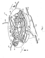
- Figure 1 is a simplified, perspective view of a first embodiment of engine, configured as a diesel engine and shown with portions broken away to reveal internal construction features;
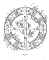
- Figure 2 is a cross-sectional view of a second embodiment of engine, configured as a two-cycle engine, the cross-sectional view being taken generally along lines A-A of Figure 1 but with certain modifications therein to illustrate the two-cycle features of this embodiment of the invention;
- Figure 3 is a cross-sectional view of a third embodiment of engine, configured as a four-cycle engine, the cross-sectional view being taken generally along lines A-A of Figure 1 but with certain modifications therein to illustrate the four-cycle features of this embodiment of the invention; and
- Figure 4 is a cross-sectional view of a fourth embodiment of engine, configured as a combination compressor/two-cycle internal combustion engine, the cross-sectional view being taken generally along lines A-A of Figure 1 but with certain modifications therein to illustrate the two-cycle and air compressor features of this embodiment of the invention.
- With reference to each of Figures 1 - 4, the overall concept of the engine revolves around a double-acting piston concept wherein pairs of pistons are mounted on each end of transecting rocker arms and cooperate in an annular cylinder.
Rocker arms shaft 29 and respectively support pistons 21 - 28 on theends pistons tie rod 16 mounted to end 12a ofrocker arm 12. Correspondingly,pistons tie rod 17 secured to end 14a ofrocker arm 14. Pistons 25 and 27 are mounted totie rod 18 joined toend 12b ofrocker arm 12 while pistons.27 and 28 are mounted to the ends oftie rod 19 secured to end 14b ofrocker arm 14. An annular cylinder 11 contains cylinder liners 36 - 39 so that coacting pairs of pistons form compression/combustion chambers 31--34, respectively, therein. For example,pistons cylinder liner 36 to form combustion/compression chamber 31. The same features are found for each of the remaining pistons 22 - 27, as will be clearly seen from each of Figures 1 - 4. - Slots 8.1 - 84 in the internal side wall of annular cylinder 11 accommodate the oscillatory movement of the respective end of
rocker arms rocker arms ends 12a and 14b towards each other bringspiston 21 andpiston 28 toward the center of combustion/compression chamber 31, thereby compressing the compressible medium therein. Correspondingly,pistons combustion chamber 33. While the foregoing event is taking place,pistons pistons compression chamber 34. Reverse movement ofrocker arms compression chambers compression chambers rocker arms - Oscillatory movement of
rocker arms cranks side gears main gear 59. Each full, oscillatory cycle of therespective rocker arm side gear - Referrring now more particularly to Figure 2, the second preferred embodiment of the novel engine apparatus of this invention is shown generally at 20 and is configured as a two-cycle, internal combustion engine. In particular, each of compression/combustion chambers 31 - 34 are configured as internal combustion chambers having spark plugs 41 - 44, respectively, mounted therein. By two-cycle operation, it is understood herein that the_ reverse movement of each of pistons 21 - 28 is a power/expansion stroke wherein a fuel/air mixture is appropriately ignited and combusted in combustion chambers 31 - 34. Correspondingly, each forward movement of pistons 21 - 28 in combination with the respective opposing piston serves as a compression stroke to compress a fuel/air mixture in the respective combustion chambers 31 - 34.
- Intake and exhaust ports are provided through the walls of annular cylinder chamber 11 and Irrespective cylinder liners 36 - 39 therein. For example,
intake ports intake ports combustion chamber 32;intake ports combustion chamber 33; andintake ports combustion chamber 34. Each of intake ports 61 - 68 are selectively interconnected through intake plenum chambers 51 - 58, respectively, each of which is selectively connected to an intake header (not shown) by intake conduits 51a - 58a, respectively. - In operation, therefore, each cfpistons 21 - 28 operates substantially identical to
piston 21 in that reverse movement ofpiston 21 exposesintake port 61 thereby allowing an appropriate fuel/air mixture to be introduced from the intake header (not shown) through intake conduit 51a intointake plenum chamber 51 thence throughintake port 61 intocombustion chamber 31. Forward movement ofpiston 21 coversintake port 61 and commences the compression of the fuel/air mixture thus obtained. - Exhaust from
combustion chamber 31 is discharged throughexhaust ports exhaust plenum chamber 61 and vented through exhaust conduit 61a into an exhaust header (not shown). Correspondingexhaust ports 72 and 73 discharge intoexhaust plenum chamber 61 and through exhaust conduit 62a..Exhaust ports exhaust plenum chamber 63 and exhaust conduit 63a.Exhaust ports exhaust plenum chamber 64 and exhaust conduit 64a. Accordingly, during a power stroke, a fuel/air mixture incombustion chamber 31, for example, is ignited at an appropriate time by a spark produced byspark plug 41 with the resulting increase in pressure forcing apartpistons cranks side gears main gear 59. Continued reverse movement ofpistons exhaust ports combustion chamber 31. Continued rearward movement ofpistons intake ports exhaust ports combustion chamber 33. The end of the power stroke centered aroundcombustion chambers combustion chambers pistons pistons pistons pistons pistons covers intake ports exhaust ports - In addition to providing a power stroke with each oscillatory movement of
rocker arms - Referring now more particularly to Figure 3, a third preferred embodiment of the novel engine apparatus of this invention is shown generally at 30 and is configured as a four-cycle, internal combustion engine. In particular, each of combustion chambers 31 - 34 incorporates therein a set of intake valves 91 - 94 and a set of exhaust valves 95 98 respectively. Intake valves 91 - 94 and exhaust valves 95 - 98 are operated by the appropriate, conventional valve actuation systems (not shown) operated by a cam-driven valve lifter system (not shown). At this point, it should be particularly understood that while a specified valve system is shown for the novel engine apparatus of this invention, it should be clearly understood that any suitable valve system could be incorporated into the novel engine apparatus and method of this invention.
- In operation and with reference particularly to
combustion chamber 31, a power cycle is commenced by the ignition of a fuel/air mixture incombustion chamber 31 byspark plug 41 igniting the fuel/air mixture with the resultant explosion, forcing apartpistons pistons exhaust valve 98 is opened, allowing the exhaust products to be discharged fromcombustion chamber 31. At the end of the forward movement ofpistons exhaust valve 98 is closed and intake valve 91 is opened allowing a fresh fuel/air mixture to entercombustion chamber 31. At the end of reverse movement ofpistons pistons combustion chamber 31 is compressed. Upon reaching the end of travel forpistons spark plug 41 initiates combustion of the same, commencing the power stroke. The power thus generated is transmitted torocker arms cranks side gears main gear 59. - While each of opposed combustion chamber pairs,
combustion chambers combustion chambers combustion chamber 31 is in the expansion/power stroke mode,combustion chamber 33 would be in the intake mode.. Simultaneously,combustion chamber 32 would be in the exhaust mode whilecombustion chamber 34 would be in the compression mode of operation. Accordingly, since there are four combustion chambers, combustion chambers 31 - 34, each combustion chamber would be selectively timed so as to fire sequentially, thereby substantially smoothing out the overall operation of four-cycle engine apparatus 30. - With additional reference to Figure 3, the elimination of each of spark plugs 41 - 44 and the appropriate modification of intake valves 91 - 94 and exhaust valves 95 - 98 could readily adapt four-
cycle engine apparatus 30 as an external combustion engine apparatus. In particular, intake ports 91 - 94 would now be configured so that an expansion fluid such as steam may be injected therethrough at the appropriate portion of the cycle as the respective pistons 21 - 28 are at their point of closest proximity. The resulting expansion would drive apart the respective pistons causing the appropriate movement ofrocker arms cycle engine apparatus 30, an external combustion engine apparatus is readily provided from what was previously considered as an internal combustion engine apparatus. - Referring now more particularly to Figure 4, a combination two-cycle, internal combustion engine/ compressor apparatus is shown generally at 40 and includes
combustion chambers internal combustion chambers cycle engine apparatus 20 shown in Figure 2. The major difference is thatcompression chambers intake valves 92 and 94 andexhaust valves combustion chambers pistons compression chamber 32 while correspondingpistons compression chamber 34. - Toward the end of the compression stroke,
exhaust valves exhaust valves intake valves 92 and 94 are opened so that air is drawn into the particular compression chamber. - In the alternative, the Figure 4 embodiment may be modified so that the combustion chambers are separated by 90° rather than being diametrically opposite, for
example chambers 31 and 34 are combustion chambers and each are provided with fuel ignition means and appropriate intake and exhaust ports. The compression chambers are then also separated by 90°, forexample chambers - It should be readily noted, therefore, with respect to each of the embodiments of the novel engine apparatus of this invention that the novel structure thereof is readily adaptable to numerous configurations for either of diesel, two-cycle, four-cycle, external combustion, or compressor operations, as may be desired.
- Referring now more particularly to Figure 1, another preferred embodiment of the novel engine apparatus of this invention is shown generally at 10.
Engine apparatus 10 is shown in perspective and is specifically configured for operations as a diesel engine in that fuel injection is provided through fuel injectors 101 - 104 into the appropriate combustion chambers. Overall, however, the valving system may be provided either as a two-cycle engine apparatus utilizing intake valves 61 - 68 and exhaust valve 71 - 78 (Figure 2) or as a four-cycle system utilizing intake valves 91 - 95 and exhaust valves 95 - 98 (Figure 3). Regardless of the particular valving system and whether a two-cycle engine or a four-cycle engine, thediesel engine apparatus 10 of this particular embodiment incorporates fuel injector systems 101 - 104 and may be supplemented with an appropriate glow plug or spark plug, such as spark plugs 41 - 44 (Figures 2 and 3). In either embodiment, power transmitted toshaft 29 bymain gear 59 is directed throughgear housing 105 into transmission/differential 106 with the power being directed toshafts shafts shaft shafts - The entire structure of
engine apparatus 10 is enclosed in anengine housing 100, the engine housing serving also as a support bearing surface forcranks shaft 29 and drives abelt 110 to drive the appropriate auxiliary equipment (not shown), as is conventional. - The invention may be embodied in other specific forms, and the described embodiments are to be considered only as illustrative.
Claims (10)
1. An engine comprising an annular cylinder, a rocker arm, opposing pistons mounted to the rocker arm and reciprocatorily operating in the annular cylinder means; and a crank connected to the rocker arm for converting reciprocatory motion of the piston and rocker arm into rotary motion.
2. An engine as claimed in.claim 1 wherein the annular cylinder comprises a toroidal cylinder chamber having an inlet for introducing a fuel/air mixture into the cylinder chamber and an exhaust means for removing exhaust products from the cylinder chamber.
3. An engine as claimed in claim 1 or claim 2 wherein the annular cylinder comprises four cylinder liners, each cylinder liner forming a combustion chamber.
4. An engine as claimed in claim 3 wherein a piston set is provided in each combustion chamber.
5. An engine as claimed in claim 4 wherein each piston set comprises a first piston carried by a first rocker arm and a second piston carried by a second rocker arm, the first and second pistons cooperating in opposed relationship in the combustion chamber.
6. An engine as claimed in claim 5 wherein a first crank interconnects the first rocker arm with a rotary gear; and a second crank interconnects the second rocker arm with the rotary gear.
7. An engine as claimed in claim 6 wherein the rotary gear is connected to a drive shaft for transmitting rotary motion from the rotary gear.
8. An engine comprising an annular cylinder in which are defined four compression chambers, first and second intersecting rocker arms, pivotally mounted about a common axis, a pair of pistons mounted at each end of each rocker arm, one piston of each pair on the first rocker arm cooperating in one of the compression chambers with an adjacent piston of a respective pair on the second rocker arm, intake and exhaust ports for the compression chambers; and cranks connected to respective ones of the rocker arms for translating oscillatory movement of the rocker arms into rotary movement.
9. An engine as claimed in claim 8 wherein two of the compression chambers are configured as compressor chambers and two of the compression chambers are configured as internal combustion engine chambers.
10. An engine as claimed in claim 8 wherein the engine is configured as a two-cycle or four-cycle internal combustion engine or as an external combustion engine.
Applications Claiming Priority (2)
| Application Number | Priority Date | Filing Date | Title |
|---|---|---|---|
| US15226280A | 1980-05-21 | 1980-05-21 | |
| US152262 | 1980-05-21 |
Publications (1)
| Publication Number | Publication Date |
|---|---|
| EP0040549A1 true EP0040549A1 (en) | 1981-11-25 |
Family
ID=22542182
Family Applications (1)
| Application Number | Title | Priority Date | Filing Date |
|---|---|---|---|
| EP81302237A Withdrawn EP0040549A1 (en) | 1980-05-21 | 1981-05-20 | Engine |
Country Status (2)
| Country | Link |
|---|---|
| EP (1) | EP0040549A1 (en) |
| JP (1) | JPS5710702A (en) |
Cited By (16)
| Publication number | Priority date | Publication date | Assignee | Title |
|---|---|---|---|---|
| US4662177A (en) * | 1984-03-06 | 1987-05-05 | David Constant V | Double free-piston external combustion engine |
| US5560324A (en) * | 1994-02-10 | 1996-10-01 | Francis David Robert Grant | Oscillating piston internal combustion engine |
| EP1061232A2 (en) * | 1999-06-16 | 2000-12-20 | Nihon Software Approach Co., Ltd. | Oscillating rotary piston engine |
| WO2002053874A1 (en) * | 2000-12-28 | 2002-07-11 | Dragomir Konstantinov | Transmission of mechanical motion |
| WO2003060291A2 (en) * | 2002-01-15 | 2003-07-24 | Branko Grahovac | Two-stroke internal combustion engine with circularly arranged pistons and cylinders |
| US6691647B2 (en) * | 1999-11-29 | 2004-02-17 | Brian Parker | Engine and drive system |
| CN100543282C (en) * | 2006-01-12 | 2009-09-23 | 李武权 | Ring-shape cylinder interal combustion engine |
| CN102322348A (en) * | 2011-10-09 | 2012-01-18 | 郭革委 | Disc piston internal combustion engine |
| CN102840027A (en) * | 2012-09-26 | 2012-12-26 | 贵州科学院 | Arc cylinder pendulum type internal combustion engine |
| ITCA20120005A1 (en) * | 2012-05-07 | 2013-11-08 | Enrichetto Casti | INTERNAL COMBUSTION ENGINE WITH DOUBLE SKY ROTATING PISTONS |
| CN104653461A (en) * | 2014-12-15 | 2015-05-27 | 康立业 | Swing type gas compressor |
| FR3043721A1 (en) * | 2015-11-16 | 2017-05-19 | Martial Maurice Jacques Robert | EXPLOSION ENGINE WITH INCURVED COMBUSTION CYLINDERS |
| CN106949052A (en) * | 2017-03-31 | 2017-07-14 | 上乘精密科技(苏州)有限公司 | A kind of circumference puts piston component |
| CN107725182A (en) * | 2016-08-12 | 2018-02-23 | 黄勃 | Ring type engine |
| CN112112734A (en) * | 2020-10-16 | 2020-12-22 | 胡杰 | Arc cylinder and piston driven crankless engine |
| CN113685289A (en) * | 2020-05-19 | 2021-11-23 | 塔格海底天然气工程有限公司 | Storage and supply system, method for supplying gas to gas engine and ship |
Families Citing this family (4)
| Publication number | Priority date | Publication date | Assignee | Title |
|---|---|---|---|---|
| JPH0741697Y2 (en) * | 1990-02-21 | 1995-09-27 | レオン自動機株式会社 | Confectionery piece transfer device |
| JPH0753529B2 (en) * | 1991-01-19 | 1995-06-07 | 中小企業事業団 | Box front and back front and back discrimination correction device |
| US7415962B2 (en) * | 2005-12-16 | 2008-08-26 | Reisser Heinz-Gustav A | Internal combustion engine |
| US8944015B2 (en) | 2005-12-16 | 2015-02-03 | Heinz-Gustav A. Reisser | Rotary piston internal combustion engine |
Citations (7)
| Publication number | Priority date | Publication date | Assignee | Title |
|---|---|---|---|---|
| DE265095C (en) * | ||||
| DE292633C (en) * | 1914-04-08 | 1916-06-20 | ||
| FR556120A (en) * | 1922-09-16 | 1923-07-12 | Manufacturing process of a real milk and cocoa jam | |
| FR718627A (en) * | 1931-06-13 | 1932-01-27 | Enhancements to two-stroke, opposed piston internal combustion engines | |
| FR1026087A (en) * | 1950-10-18 | 1953-04-23 | Improvement in thermal engines and more particularly those known as: explosion or internal combustion | |
| DE1942033A1 (en) * | 1969-08-19 | 1971-03-04 | Czaika Paul Peter | Czaika engine |
| AU455824B2 (en) * | 1971-02-16 | 1974-11-18 | Cano, Sera Fin | Oscillating internal combustion engine |
-
1981
- 1981-05-20 EP EP81302237A patent/EP0040549A1/en not_active Withdrawn
- 1981-05-20 JP JP7509181A patent/JPS5710702A/en active Pending
Patent Citations (7)
| Publication number | Priority date | Publication date | Assignee | Title |
|---|---|---|---|---|
| DE265095C (en) * | ||||
| DE292633C (en) * | 1914-04-08 | 1916-06-20 | ||
| FR556120A (en) * | 1922-09-16 | 1923-07-12 | Manufacturing process of a real milk and cocoa jam | |
| FR718627A (en) * | 1931-06-13 | 1932-01-27 | Enhancements to two-stroke, opposed piston internal combustion engines | |
| FR1026087A (en) * | 1950-10-18 | 1953-04-23 | Improvement in thermal engines and more particularly those known as: explosion or internal combustion | |
| DE1942033A1 (en) * | 1969-08-19 | 1971-03-04 | Czaika Paul Peter | Czaika engine |
| AU455824B2 (en) * | 1971-02-16 | 1974-11-18 | Cano, Sera Fin | Oscillating internal combustion engine |
Cited By (20)
| Publication number | Priority date | Publication date | Assignee | Title |
|---|---|---|---|---|
| US4662177A (en) * | 1984-03-06 | 1987-05-05 | David Constant V | Double free-piston external combustion engine |
| US5560324A (en) * | 1994-02-10 | 1996-10-01 | Francis David Robert Grant | Oscillating piston internal combustion engine |
| EP1061232A2 (en) * | 1999-06-16 | 2000-12-20 | Nihon Software Approach Co., Ltd. | Oscillating rotary piston engine |
| EP1061232A3 (en) * | 1999-06-16 | 2002-04-17 | Nihon Software Approach Co., Ltd. | Oscillating rotary piston engine |
| US6691647B2 (en) * | 1999-11-29 | 2004-02-17 | Brian Parker | Engine and drive system |
| WO2002053874A1 (en) * | 2000-12-28 | 2002-07-11 | Dragomir Konstantinov | Transmission of mechanical motion |
| WO2003060291A2 (en) * | 2002-01-15 | 2003-07-24 | Branko Grahovac | Two-stroke internal combustion engine with circularly arranged pistons and cylinders |
| WO2003060291A3 (en) * | 2002-01-15 | 2003-10-09 | Branko Grahovac | Two-stroke internal combustion engine with circularly arranged pistons and cylinders |
| CN100543282C (en) * | 2006-01-12 | 2009-09-23 | 李武权 | Ring-shape cylinder interal combustion engine |
| CN102322348B (en) * | 2011-10-09 | 2014-04-16 | 郭革委 | Disc piston internal combustion engine |
| CN102322348A (en) * | 2011-10-09 | 2012-01-18 | 郭革委 | Disc piston internal combustion engine |
| ITCA20120005A1 (en) * | 2012-05-07 | 2013-11-08 | Enrichetto Casti | INTERNAL COMBUSTION ENGINE WITH DOUBLE SKY ROTATING PISTONS |
| CN102840027A (en) * | 2012-09-26 | 2012-12-26 | 贵州科学院 | Arc cylinder pendulum type internal combustion engine |
| CN104653461A (en) * | 2014-12-15 | 2015-05-27 | 康立业 | Swing type gas compressor |
| FR3043721A1 (en) * | 2015-11-16 | 2017-05-19 | Martial Maurice Jacques Robert | EXPLOSION ENGINE WITH INCURVED COMBUSTION CYLINDERS |
| WO2017085364A1 (en) * | 2015-11-16 | 2017-05-26 | Robert Martial | Combustion engine with curved combustion cylinders |
| CN107725182A (en) * | 2016-08-12 | 2018-02-23 | 黄勃 | Ring type engine |
| CN106949052A (en) * | 2017-03-31 | 2017-07-14 | 上乘精密科技(苏州)有限公司 | A kind of circumference puts piston component |
| CN113685289A (en) * | 2020-05-19 | 2021-11-23 | 塔格海底天然气工程有限公司 | Storage and supply system, method for supplying gas to gas engine and ship |
| CN112112734A (en) * | 2020-10-16 | 2020-12-22 | 胡杰 | Arc cylinder and piston driven crankless engine |
Also Published As
| Publication number | Publication date |
|---|---|
| JPS5710702A (en) | 1982-01-20 |
Similar Documents
| Publication | Publication Date | Title |
|---|---|---|
| EP0040549A1 (en) | Engine | |
| US6484687B1 (en) | Rotary machine and thermal cycle | |
| JP3016485B2 (en) | Reciprocating 2-cycle internal combustion engine without crank | |
| US3895620A (en) | Engine and gas generator | |
| US4437441A (en) | Rotary alternating piston gas generator | |
| US4586881A (en) | Machine having integral piston and cylinder wall sections | |
| EP0717812B1 (en) | Engine | |
| US3857370A (en) | Rotary internal combustion engine | |
| JP3377968B2 (en) | Internal combustion rotary engine and compressor | |
| US5138993A (en) | Rotary wavy motion type engine | |
| KR200303198Y1 (en) | shuttle linkage engine | |
| RU2477376C2 (en) | Internal combustion engine: five-stroke rotary engine with rotary gates, separate working medium compression and expansion sections, and isolated invariable-volume combustion chambers | |
| US20030121482A1 (en) | One-stroke internal combustion engine | |
| US2462092A (en) | Opposed piston engine | |
| EP1085182B1 (en) | Internal combustion rotary engine | |
| RU2067187C1 (en) | Torus-ring piston machine | |
| WO2000036288A2 (en) | Pairing of combustion chambers in engines | |
| GB2227522A (en) | Opposed piston twin crankshaft I.C. engine | |
| KR100336159B1 (en) | Combustion Motor | |
| EP0413541A1 (en) | Rotary internal combustion engine | |
| US4249492A (en) | Constant torque rotary engine | |
| GB2069041A (en) | Crankcase compression four- stroke engine | |
| RU2094628C1 (en) | Piston internal combustion engine | |
| US1643581A (en) | Internal-combustion engine | |
| RU2002085C1 (en) | Internal combustion engine |
Legal Events
| Date | Code | Title | Description |
|---|---|---|---|
| PUAI | Public reference made under article 153(3) epc to a published international application that has entered the european phase |
Free format text: ORIGINAL CODE: 0009012 |
|
| AK | Designated contracting states |
Designated state(s): AT BE CH DE FR GB IT LU NL SE |
|
| STAA | Information on the status of an ep patent application or granted ep patent |
Free format text: STATUS: THE APPLICATION IS DEEMED TO BE WITHDRAWN |
|
| 18D | Application deemed to be withdrawn |
Effective date: 19821030 |