EP0040309A2 - Rekursives Informationsverarbeitungssystem und Gerät zur rekursiven Dekodierung einer augenblicklichen FIFO binären arithmetischen Zeichenkette - Google Patents
Rekursives Informationsverarbeitungssystem und Gerät zur rekursiven Dekodierung einer augenblicklichen FIFO binären arithmetischen Zeichenkette Download PDFInfo
- Publication number
- EP0040309A2 EP0040309A2 EP81102415A EP81102415A EP0040309A2 EP 0040309 A2 EP0040309 A2 EP 0040309A2 EP 81102415 A EP81102415 A EP 81102415A EP 81102415 A EP81102415 A EP 81102415A EP 0040309 A2 EP0040309 A2 EP 0040309A2
- Authority
- EP
- European Patent Office
- Prior art keywords
- fsm
- processor
- component
- value
- present
- Prior art date
- Legal status (The legal status is an assumption and is not a legal conclusion. Google has not performed a legal analysis and makes no representation as to the accuracy of the status listed.)
- Withdrawn
Links
- 239000013598 vector Substances 0.000 claims abstract description 9
- 230000002452 interceptive effect Effects 0.000 claims abstract description 3
- 238000004364 calculation method Methods 0.000 claims description 5
- 230000004044 response Effects 0.000 abstract description 3
- 230000001360 synchronised effect Effects 0.000 abstract description 3
- 230000008901 benefit Effects 0.000 abstract description 2
- 230000006870 function Effects 0.000 description 15
- 238000000034 method Methods 0.000 description 11
- 238000011144 upstream manufacturing Methods 0.000 description 10
- 230000001934 delay Effects 0.000 description 8
- 208000025766 lethal multiple pterygium syndrome Diseases 0.000 description 8
- 230000008569 process Effects 0.000 description 8
- 238000010606 normalization Methods 0.000 description 6
- 238000012545 processing Methods 0.000 description 6
- 238000010586 diagram Methods 0.000 description 5
- 230000009471 action Effects 0.000 description 3
- 230000003750 conditioning effect Effects 0.000 description 3
- 238000013459 approach Methods 0.000 description 2
- 238000005192 partition Methods 0.000 description 2
- 238000012360 testing method Methods 0.000 description 2
- 206010015137 Eructation Diseases 0.000 description 1
- 230000006978 adaptation Effects 0.000 description 1
- 238000007906 compression Methods 0.000 description 1
- 230000006835 compression Effects 0.000 description 1
- 230000008878 coupling Effects 0.000 description 1
- 238000010168 coupling process Methods 0.000 description 1
- 238000005859 coupling reaction Methods 0.000 description 1
- 230000001351 cycling effect Effects 0.000 description 1
- 238000013144 data compression Methods 0.000 description 1
- 238000013461 design Methods 0.000 description 1
- 230000009977 dual effect Effects 0.000 description 1
- 238000003780 insertion Methods 0.000 description 1
- 230000037431 insertion Effects 0.000 description 1
- 230000001960 triggered effect Effects 0.000 description 1
Images


Classifications
-
- H—ELECTRICITY
- H03—ELECTRONIC CIRCUITRY
- H03M—CODING; DECODING; CODE CONVERSION IN GENERAL
- H03M7/00—Conversion of a code where information is represented by a given sequence or number of digits to a code where the same, similar or subset of information is represented by a different sequence or number of digits
- H03M7/30—Compression; Expansion; Suppression of unnecessary data, e.g. redundancy reduction
- H03M7/40—Conversion to or from variable length codes, e.g. Shannon-Fano code, Huffman code, Morse code
- H03M7/4006—Conversion to or from arithmetic code
Definitions
- This invention can be regarded as a means for ensuring continuous flow through a pipeline processor.
- the invention relates to measures needed to speed up the serial decoding of a FIFO Rissanen/Langdon arithmetic binary encoded string.
- the binary arithmetic coding as described in the co-pending 285 application generates an instantaneous F I FO binary arithmetic code string C(sb).
- This string is recursively formed by the high to low order pairwise combining of digits of a decodable set of relatively shifted finite binary number strings C(s) and/or A(sb).
- C(s) is the encoded string corresponding to source string s
- A(sb) is an augend function for symbol b given prior string s.
- the encoding action is in response to each binary symbol b occurring in the symbol string s. In this latter regard "q" of the lowest order bits of each string C(s) and A(sb) are combined during each recursion.
- arithmetic code string carries are controlled through control character insertions after predetermined length runs of consecutive l's.
- the encoder determines that the symbol to be encoded is LPS, then the encoder adds TA to the working end of the code stream so as to form a new working end. At the same time, the encoder left shifts out k bits from the working end of the code string and similarly shifts the contents of the designated register (register C). The internal state T of the encoder remains unchanged.
- the encoder tests for normalization. The test for normalization involves the leftmost bit of T A. If the leftmost bit is "1", then TA is already "normalized”. A normalized value of T is assigned the value TA. If the leftmost bit of TA is "0", then the most significant bit in designated register C is outputted. Next, TA is normalized: left shifted one bit and assigned as the value of T. The designated register C is left shifted one bit.
- the decoder as described in the co-pending 285 application needs only to subtract and shift.
- the decoder has the q most significant bits of the code stream in a designated register r C and has an internal state represented by the number T.
- the above objects are satisfied in.an embodiment of an apparatus for ensuring continuous flow through a pipeline processor as it relates to the serial decoding of FIFO Rissanen/Langdon arithmetic string code of binary sources.
- the pipeline decoder includes a processor (11, 23) and a finite state machine (21, FSM) in interactive signal relation.
- the processor generates output binary source signals (18), status signals (WASMPS, 31) and K component/K candidate next integer-valued control parameters (LQ, k0; Ll, kl; 25).
- These signals and parameters are generated in response to the concurrent application of one bit from successive arithmetic code bits, a K component present integer-valued control parameter (52), and K component vector representation (T, TA) of the present internal state (51) of the associated finite state machine (FSM).
- the FSM makes a K-way selection from K candidate next internal states and K candidate next control parameters. This selection is made in no more than K 2 + K computation cycles.
- the selected signals are then applied to the processor in a predetermined displaced time relation to the present signals in the processor.
- this system takes advantage of the multi-state or "memory" capability of an FSM in order to control the inter-symbol influence and facilitate synchronous multi-stage pipeline decoding.
- the processor comprises a shift and subtract circuit for magnitude comparison between the arithmetic code string and an updated trial augend for purposes of generating the binary source symbol output.
- the FSM uses status signals from the processor and the FSM's present internal state for making the K-way selection of the next trial augend in overlap relation with-the shift and subtract decode operation of the first processor.
- the particular problem solved is that of constructing a high-speed decoder for a data compression code.
- the general problem solved is the design of a pipeline where a finite state machine (FSM) comprises one of the functions (or subfunctionsl to be performed. That is, the system has upstream controls (signals) from downstream in the pipeline which influence the output and next state of the upstream pipeline unit.
- FSM finite state machine
- the present embodiment depicts the high-speed decoding of a compressed binary stream using the binary multiplicative arithmetic code described in the co-pending application, Langdon, et al, USSN 098,285, filed November 29, 1979.
- Arithmetic string encoding involves the encoding and decoding of one-bit binary symbols (0 or 1) under statistics summarized by an r-bit quantity Q.
- Q includes a description of the less probable symbol (LPS).
- L less probable symbol
- Q could be formed, for example, of five bits, one bit of which, designated L, denotes whether 0 or 1 is less probable; and a skew number k which indicates that the probability of L, i.e., p(L) is approximated by 2- k .
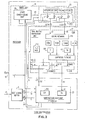
- FIG. 1 there is shown a block diagram of receiver 1, including a binary arithmetic decoder 3 in its environment.
- a buffer unit 5 provides the decoder 3 with input C(s) over path 7.
- the buffer takes the next, say, 16 bits of decode string C(s) and properly aligns it.
- Buffer 5 receives from the decoder 3 a signal SA on path 9.
- SA denotes "shift amount”.
- SA indicates how many bits of C(s) were transferred from buffer 5 to decoder 3.
- Decoder 3 emits a 1-bit symbol b(i) during each decoding cycle as governed by a clock signal over path 15.
- the clock signal on path 15 coordinates (synchronizes) buffer 5, decoder 3 and model unit 11.
- the source data string originally encoded to form the code string C(s) is itself denominated where the symbols "b" are bit values (0 or 1).
- the encoded source string C(s) is applied as an input on path 17 of receiver 1.
- Both the encoding and decoding processes involve a double recursion.
- the first recursion concerns the code string C(s), while the second recursion includes an internal variable T(s).
- T is stored as a running parameter in a 16-bit register 109 in trial augend calculation unit 21 as depicted in Figure 5.
- the leftmost q 16 bits of C(s) are placed in a 16-bit register CR 201, as shown in Figure 6 of the shift and subtract unit 23. Further, register T is set to all 1's. It should be remembered that the decoding process is the dual of the encoding process. During encoding, augends were added to the code string C(s) and the result was shifted left. For decoding, augends are subtracted and the result left shifted.
- the decoder must perform several sequential steps before the value of the decoded bit stream is known. Initially, the value of Q under which the next bit was encoded and the value of T are known. These steps were previously described in the background portion of the specification. It is sufficient to remark that as the string C(s) is decoded, the higher order bits in register CR 201 ( Figure 6) are converted to 0's by the subtraction operations. As the CR contents are shifted left, these O's are shifted out and the lesser significant bits of string C(s) are shifted left into register CR, filling the vacated positions in the register. Therefore, the 16 next most significant bits of C(s) must feed a shifter ready to be reinserted to their new positions when CR is shifted.
- the receiver logic including the decoder 3 and model unit 11.
- the above-mentioned 3-step partition is functionally embodied in the apparatus.
- the buffer unit 5 manages the code string and furnishes the higher order bits of C(s) as required.
- Step 1 i.e., that of aligning values and updating the variables, can be implemented by a table look-up procedure.
- Attention is directed to model unit 11 in Figure 2.
- This model includes a state conditioning unit 28 formed from a shift register 281, parallel path readout means 30 and a table look-up unit 25.
- the output of decoder 3 is fed back over path 18 into shift register 281 of state conditioning unit 28.
- the instantaneous present output b(i), together with the past history b (i - 1), b (i - 2), b (i - 3)...on path 30, constitutes the address for accessing a 5-bit quantity from table look-up unit 25 (TLU).
- Step 2 both operate upon internal variable T for the next state, as well as calculate the output, trial augend TA.
- the apparatus for implementation is called the trial augend calculation unit (TAC) 21.
- the value of the most recently decoded symbol is required information for TAC in order to determine the value T(i + 1).
- Step 3 determines the value b(i) by way of a subtraction operation. The result is then shifted left by 0, 1, or k bits.
- the apparatus embodying the Step 3 functions is called the SUBTRACT AND SHIFT UNIT (SAS) 23.
- SAS receives the value k(i), L(i), and TA(i) from the TAC unit.
- the SAS also receives the leading bits from the code string C(s) from buffer unit 5. These leading bits fill the vacated position of the dedicated register CR within the SAS.
- the SAS outputs the value b(i) and LPS (i).
- the embodiment in Figure 2 were operated in an overlapped manner. This results from the fact that the delays of each unit occur in series. For example, once b(i) is known, the TLU obtains k(i + 1) and L(i + 1). From MPS (i) the TAC updates the internal variable T(i + 1). From k(i + 1), the TAC calculates TA(i + 1) and awaits the result LPS(i + 1) before updating T. In turn, the SAS unit calculates LPS(i + 1) from the values CR(i + 1) and TA(i + l). Likewise, SAS calculates b(i + 1) from LPS(i + 1) and L(i + 1).
- the minimum time of cycling the decoder unit would be the maximum delay through one of the three units instead of the sum of the maximum delays of the three units.
- TLU would generate the values k(i + 2) and L (i + 2) while TAC-would update the trial augend-TA(i + 1). Overlapped with this SAS would compute b(i).
- the TLU must know b(i) and b(i + 1) before it can generate k(i + 2) and L(i + 2).
- the TAC must know LPS(i) before it can determine T (i + 1) which is needed in order to calculate TA(i + 1).
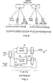
- FIG. 3 there is disclosed a block diagram of the invention, showing the model unit, TAC, and SAS, their registers and the interface signals. Of interest here are the global, rather than the local aspects of the invention.
- TAC can calculate two trial augends. One trial augend, if b(i) is LPS. This is designated TALPS(i + 1). The second trial augend calculated by TAC occurs for the case where b(i) is MPS. This, in turn, is designated TAMPS(I + 1).
- TAC unit determines two values for T (i + 1). The first value for the case of the symbol b(i) is LPS. The second value is if b (i) is MPS.
- the data selector 253 in TLU unit 25 may be formed from 2 x 1 MUX units.
- Each of the four ordered pairs (L00,k00); (L01,k01); ( L 10, klO); (Lll,kll) is applied two pairs at a time to respective ones of the MUX units.
- the value of b(i) on path 18 conditions which one of the respective pair will appear on the counterpart path 33 and 35 to be applied in turn to the TAC.
- the TLU determines the Q value pairs with respect to k(i + 2) and L(i + 2), while the TAC processes TA(i + 1) and k(i + 1). Overlapped with this, the SAS unit decodes b(i) as applied to the TLU unit. SAS also generates WASMPS (i) sent to the TAC over path 31.
- the conditioning class address minus'the bits representing b(i) and b(i + 1) does the look-up in, for example, a 20-bit wide memory instead of one 5 bits wide.
- the proper ordered pair (L,k) is selected once b(i) is known.
- the selected pair on either path 33 or 35 is then passed to the TAC unit.
- the SAS unit receives L(i), k(i), over line 27 and TA(i) on line 51. It should be noted that a 2 x 1 MUX status selector is controlled by the WASMPS output on path 31 in the electrical connection between TAC and SAS.
- TAC and SAS may be viewed respectively as an upstream and downstream processor.
- the unpipelined TAC unit in Figure 2 may be characterized as an FSM with the value T as its internal state.
- T the value of TA is calculated.
- WASMPS the outcome "WASMPS” may be calculated by the downstream processor SAS.
- WASMPS the next value.T is calculated.
- the signal WASMPS may be viewed as a control signal passed upstream back to the TAC. This is designated as "upstream control.”
- next value of T is not determined until the old value of TA is used for the generation of WASMPS.
- TAC is a finite state machine
- the next state function result is not available at the end of a cycle.
- the value of the next state function can be narrowed to one-of two possibilities. If each of the possibilities is treated as "a present state", then two candidate values of TA can be calculated, one from each "present” state. However, from each present state, there will be two next-state possibilities.
- the TLU unit passes to the TAC unit 21 two 5-bit quantities (LOO,kOO); (L01,k01); (L01,k10); (Lll,kll). If b(i) is "0", then LOkO is the correct ordered pair Q. If b(i) is "1", then Llkl is the correct Q. Once b(i - 1) is known, then L(i), the value of the least probable symbol for bits position i, is known. As an example, before symbol b(l) is decoded, the value L(l) is known.
- L0(i + 1), k0(i + 1), Ll(i + 1), and kMPS(i + 1) can be readily converted into LLPS(i + 1), kLPS(i + 1), LMPS(i + 1), and kMPS(i + 1) using the value L(i). If L(i) is "0", then LLPS and kLPS are equal to LO and k0, respectively, while LMPS and kMPS are Ll and kl, respectively. On the other hand, if L(i) is "1", then LLPS and kLPS are Ll and kl, respectively, while LMPS and kMPS are LO and k0, respectively.
- Gating network 210 in Figure 3 is shown implemented in Figure 5 by a pair of 2 x 1 MUX circuits 212 and 214.
- the MUX circuits have their inputs cross-connected such that path 35 is terminated in a 1 input for MUX 214 and a 0 input for MUX 212.
- Path 33 is terminated in a "1" input for MUX.212 and a "0" input for MUX 214.
- the L (i) output from register 216 controls the Q value to be selected by way of the L(i) signal applied over path 218.
- T a pair of values for the internal variable T, stored in register 109, T assuming one value if b(i) is LPS and the other if b(i) is MPS.
- T(l) the initial value, i.e., 0.11111...1 since L(l) and k (1) are known, then TA (1) is determined.
- the TAC must calculate TALPS(2) and TAMPS(2) without knowing the value b (1).
- TLU unit has passed L0,K0, Ll,kl for bit position 2. Since L(l) is known, these can be converted as previously described to LLPS(2), kLPS(2), LMPS(2), and kMPS(2). Values TLPS(2) and TMPS(2) must be calculated for bit position 2. This may be accomodated if b(l) is LPS, then TLPS is T(l), because the occurrence of the LPS symbol leaves T unchanged according to the algorithm. On the other hand, if b(l) is MPS, then TMPS is "TA(1) normalized.” This is denoted by TA(1)NORM. Consequently, the values for TAMPS and TALPS for bit position i + 1 are defined by the following relations:
- the new value of L is used to convert L0,...,k1 to the required value in terms of LLPS,...,kMPS.
- the value k(i + 1) is now known. Thus, this value may be passed on to the SAS unit.
- the value k(i + 1) is needed so that the SAS unit knows the amount to shift left register CR (depicted as register 201 in Figure 6) in case the symbol b(i + 1) was LPS.
- LLPS Values LLPS, LMPS, kLPS and kMPS are in respective registers 115, 117, 119 and 121.
- Internal states T and TA norm are in respective registers 109 and 111 at the start of a cycle.
- Eq. 2 to calculate TAMPS, is embodied by shifter 129 responsive to kLPS signal'125, adder 127 which subtracts the shifted T from itself, forming TALPS.
- Eg. 3 is embodied by shifter 137 and adder 135, forming TAMPS.
- one of candidates TALPS and TAMPS is selected through MUX 124, forming TAN 51.
- Selection signal WASMPS 31 is generated by SAS. If WASMPS 31 is "1", TAMPS is passed through M U X 124; otherwise TALPS is passed.
- Bus TAN 51 goes to SAS, but also feeds MUX 220.
- Select signal 221 is the most significant bit TAN(0), which if "0", calls for normalization.
- the normalized bus 222 is loaded into TA norm at the end of the cycle.
- WASMPS also selects the value L, K to be passed to the SAS unit along with TAN. This is done by MUX 123, feeding register 216.
- MUX 123 implements equations 4 and 5, and register 216 holds the result for SAS for the next cycle.
- WASMPS 31 also controls the proper permutation through unit 210 of values. LLPS, LMPS, kLPS, and kMPS.from the inputs Ll, kl, 33 and L0, k0, 35, furnished by the TLU unit 25.
- E q. 6 is implemented by clocking into TA norm the normalized value selected for TAN and leaving register T 109 alone.
- Eq. 7 also .selects normalized TAN, but transfers the value of TA norm to T for the next cycle.
- the subtractor determines the value of MPS. This causes WASMPS 31 to be 0 or 1, and accordingly select the value for the next TAN 51, L, k 216, and permutation LLPS, LMPS, kLPS and kMPS in unit 210.
- register CR 201 holds the working end of the code string being decoded, with the next lesser significant bits waiting on bus 7 to be.shifted and appended through unit 203 to replace the bits of CR 201 which are shifted out.
- value TA N 51 is subtracted from CR 201.
- Adder C/OUT signal, called WASLPS is inverted to generate signal WASMPS 31. If signal WASMPS is active, then CR is shifted left only if TAN(O) is "0", signifying normalization.
- the delay which determines the fastest cycle time includes a flip-flop propagation delay tP(FF) to store value b(i), and the contents of CR register 201 of SAS unit 23, a table look-up access delay tA(TLU), a 16-bit barrel shifter propagation delay tP(shift) for augent TA, a subtractor propagation-delay tP(sub) for the addend TA, a 16-bit subtractor delay tP(sub) for the value CR - TA, and a 16-bit shifter delay tP(shift) to realign CR - TA by a k-bit shift, and finally a flip-flop set-up delay tSU(FF) for the edge-triggered flip-flops which are-used in the embodiment.
- the delay is thus equal to the sum of the incrmental delays as expressed by DELAY
- the delays occur in parallel so that the delay determining the fastest cycle time is the maximum of the individual unit delays.
- the three units which are overlapped are the TLU, the TAC and the SAS. Their delay times may be represented as follows:
- the output value of the final decoder unit of the pipeline in this invention influences the upstream units via an upstream control signal "WASMPS". Since the final unit (SAS) output must select between two candidate inputs to the SAS, then the TAC unit must generate two candidate outputs. If a unit output, i.e., from the T LU is two pipeline units (hence, two clock times) away from the last (SAS) unit output, then the pipeline must work on four possible outputs if the SAS unit current output depends on the two previous outputs. This increases by a power of two for each clock time.
- WASMPS upstream control signal
- the decoder in pipeline operation includes a finite state machine (FSM).
- FSM finite state machine
- TAC unit the internal variable
- An FSM not only delivers an output each cycle, but updates an internal state. The output is a function of the input and the internal state.
- the pipeline of the next state function occurs without interruption of the pipeline. This means that at each pipeline clock, a new input value and a new present state value are presented. In the event that there are delays, as for example in the output of the next state function, then there is a "burping" of the data stream throughput. This is cured in this invention by pipelining the next state function such that the next state is clocked out by a signal coming from a downstream unit rather than the synch unit.
Landscapes
- Engineering & Computer Science (AREA)
- Theoretical Computer Science (AREA)
- Complex Calculations (AREA)
- Advance Control (AREA)
- Compression, Expansion, Code Conversion, And Decoders (AREA)
- Multi Processors (AREA)
Applications Claiming Priority (2)
| Application Number | Priority Date | Filing Date | Title |
|---|---|---|---|
| US06/143,986 US4295125A (en) | 1980-04-28 | 1980-04-28 | Method and means for pipeline decoding of the high to low order pairwise combined digits of a decodable set of relatively shifted finite number of strings |
| US143986 | 1988-01-14 |
Publications (2)
| Publication Number | Publication Date |
|---|---|
| EP0040309A2 true EP0040309A2 (de) | 1981-11-25 |
| EP0040309A3 EP0040309A3 (de) | 1982-10-27 |
Family
ID=22506565
Family Applications (1)
| Application Number | Title | Priority Date | Filing Date |
|---|---|---|---|
| EP81102415A Withdrawn EP0040309A3 (de) | 1980-04-28 | 1981-03-31 | Rekursives Informationsverarbeitungssystem und Gerät zur rekursiven Dekodierung einer augenblicklichen FIFO binären arithmetischen Zeichenkette |
Country Status (3)
| Country | Link |
|---|---|
| US (1) | US4295125A (de) |
| EP (1) | EP0040309A3 (de) |
| JP (1) | JPS56162154A (de) |
Families Citing this family (25)
| Publication number | Priority date | Publication date | Assignee | Title |
|---|---|---|---|---|
| JPS57134774A (en) * | 1981-02-13 | 1982-08-20 | Hitachi Ltd | Vector operating device |
| US4652856A (en) * | 1986-02-04 | 1987-03-24 | International Business Machines Corporation | Multiplication-free multi-alphabet arithmetic code |
| US4935882A (en) * | 1986-09-15 | 1990-06-19 | International Business Machines Corporation | Probability adaptation for arithmetic coders |
| US4905297A (en) * | 1986-09-15 | 1990-02-27 | International Business Machines Corporation | Arithmetic coding encoder and decoder system |
| US4891643A (en) * | 1986-09-15 | 1990-01-02 | International Business Machines Corporation | Arithmetic coding data compression/de-compression by selectively employed, diverse arithmetic coding encoders and decoders |
| US5333212A (en) * | 1991-03-04 | 1994-07-26 | Storm Technology | Image compression technique with regionally selective compression ratio |
| JP3123792B2 (ja) * | 1991-11-05 | 2001-01-15 | 株式会社リコー | 算術符号を用いる符号化装置および復号化装置 |
| CA2077271C (en) * | 1991-12-13 | 1998-07-28 | David J. Craft | Method and apparatus for compressing data |
| US5396228A (en) * | 1992-01-16 | 1995-03-07 | Mobile Telecommunications Technologies | Methods and apparatus for compressing and decompressing paging data |
| US5325401A (en) * | 1992-03-13 | 1994-06-28 | Comstream Corporation | L-band tuner with quadrature downconverter for PSK data applications |
| US5563595A (en) * | 1993-12-23 | 1996-10-08 | International Business Machines Corporation | Method and apparatus for compressing data |
| KR960015195A (ko) * | 1994-10-31 | 1996-05-22 | 배순훈 | 트리 구조 이원 연산 코딩 장치 |
| US6055338A (en) * | 1996-08-22 | 2000-04-25 | Sumitomo Metal Industries Limited | Bi-level adaptive coding using a dual port memory and a context comparator |
| US6058216A (en) * | 1996-09-03 | 2000-05-02 | Sumitomo Metal Industries Limited | Apparatus for encoding image data |
| US5818368A (en) * | 1997-04-18 | 1998-10-06 | Premier Research, Llc | Method and apparatus for lossless digital data compression |
| US6892343B2 (en) | 2000-03-27 | 2005-05-10 | Board Of Regents Of The University Of Nebraska | System and method for joint source-channel encoding, with symbol decoding and error correction |
| FR2813484A1 (fr) * | 2000-08-31 | 2002-03-01 | Koninkl Philips Electronics Nv | Traitement de donnees en une serie temporelle d'etapes |
| US6714145B1 (en) | 2002-09-26 | 2004-03-30 | Richard Marques | Method and apparatus for integer-based encoding and decoding of bits |
| US8176155B2 (en) * | 2003-11-26 | 2012-05-08 | Riip, Inc. | Remote network management system |
| KR100648258B1 (ko) * | 2004-08-02 | 2006-11-23 | 삼성전자주식회사 | 고속의 디코딩을 수행하는 파이프라인 구조의 내용 기반적응적 이진 산술 디코더 |
| US7161507B2 (en) * | 2004-08-20 | 2007-01-09 | 1St Works Corporation | Fast, practically optimal entropy coding |
| WO2007002468A2 (en) * | 2005-06-23 | 2007-01-04 | 1Stworks Corporation | Modeling for enumerative encoding |
| JP4779977B2 (ja) * | 2007-01-12 | 2011-09-28 | 株式会社日立製作所 | 画像符号化・復号化装置 |
| US8779950B2 (en) | 2012-03-05 | 2014-07-15 | Dcba, Llc | Command encoded data compression |
| US9543980B2 (en) | 2014-10-10 | 2017-01-10 | Massachusettes Institute Of Technology | Systems and methods for model-free compression and model-based decompression |
Family Cites Families (4)
| Publication number | Priority date | Publication date | Assignee | Title |
|---|---|---|---|---|
| US4025771A (en) * | 1974-03-25 | 1977-05-24 | Hughes Aircraft Company | Pipe line high speed signal processor |
| US4099257A (en) * | 1976-09-02 | 1978-07-04 | International Business Machines Corporation | Markov processor for context encoding from given characters and for character decoding from given contexts |
| US4122440A (en) * | 1977-03-04 | 1978-10-24 | International Business Machines Corporation | Method and means for arithmetic string coding |
| US4286256A (en) * | 1979-11-28 | 1981-08-25 | International Business Machines Corporation | Method and means for arithmetic coding utilizing a reduced number of operations |
-
1980
- 1980-04-28 US US06/143,986 patent/US4295125A/en not_active Expired - Lifetime
-
1981
- 1981-03-20 JP JP3973481A patent/JPS56162154A/ja active Granted
- 1981-03-31 EP EP81102415A patent/EP0040309A3/de not_active Withdrawn
Also Published As
| Publication number | Publication date |
|---|---|
| JPS56162154A (en) | 1981-12-12 |
| US4295125A (en) | 1981-10-13 |
| JPS6114532B2 (de) | 1986-04-19 |
| EP0040309A3 (de) | 1982-10-27 |
Similar Documents
| Publication | Publication Date | Title |
|---|---|---|
| US4295125A (en) | Method and means for pipeline decoding of the high to low order pairwise combined digits of a decodable set of relatively shifted finite number of strings | |
| US4467317A (en) | High-speed arithmetic compression coding using concurrent value updating | |
| US4463342A (en) | Method and means for carry-over control in the high order to low order pairwise combining of digits of a decodable set of relatively shifted finite number strings | |
| US4286256A (en) | Method and means for arithmetic coding utilizing a reduced number of operations | |
| EP1859360B1 (de) | Verfahren und vorrichtung zum produzieren eines indexvektors zur verwendung bei der durchführung einer vektorpermutationsoperation | |
| JPH0144058B2 (de) | ||
| US6754870B2 (en) | CRC operation unit and CRC operation method | |
| US5625356A (en) | Method for re-synchronizing variable length code at high speed using parallel-processing pattern matching | |
| WO2008039321A2 (en) | Iterative process with rotated architecture for reduced pipeline dependency | |
| US6101621A (en) | Logic circuit and method for designing the same | |
| US5097436A (en) | High performance adder using carry predictions | |
| US6751773B2 (en) | Coding apparatus capable of high speed operation | |
| US5339267A (en) | Preprocessor of division device employing high radix division system | |
| US6009128A (en) | Metric acceleration on dual MAC processor | |
| US7839936B2 (en) | Method and system for determining a number of data packets required to transport a data block | |
| JP3184670B2 (ja) | 画像符号化装置 | |
| EP1096380A1 (de) | Prozessor | |
| CN110598172B (zh) | 一种基于csa加法器的卷积运算方法和电路 | |
| EP0079333B1 (de) | Schnelle arithmetische kompressionscodierung mit gleichzeitiger werteaktualisierung | |
| CN114895868B (zh) | 基于两位商计算的除法运算单元及除法器 | |
| JP3219571B2 (ja) | 画像符号化装置及び方法 | |
| CN117785108B (zh) | 一种前导数处理方法、系统、设备及存储介质 | |
| CN121077466A (zh) | 一种混合式时序跳变先导零检测电路 | |
| JP3595659B2 (ja) | パッキング回路 | |
| JPH03255723A (ja) | 可変ビット長のパッキング処理方法及び装置 |
Legal Events
| Date | Code | Title | Description |
|---|---|---|---|
| PUAI | Public reference made under article 153(3) epc to a published international application that has entered the european phase |
Free format text: ORIGINAL CODE: 0009012 |
|
| AK | Designated contracting states |
Designated state(s): DE FR GB IT |
|
| PUAL | Search report despatched |
Free format text: ORIGINAL CODE: 0009013 |
|
| AK | Designated contracting states |
Designated state(s): DE FR GB IT |
|
| 17P | Request for examination filed |
Effective date: 19821116 |
|
| STAA | Information on the status of an ep patent application or granted ep patent |
Free format text: STATUS: THE APPLICATION IS DEEMED TO BE WITHDRAWN |
|
| 18D | Application deemed to be withdrawn |
Effective date: 19840514 |
|
| RIN1 | Information on inventor provided before grant (corrected) |
Inventor name: LANGDON, GLEN GEORGE, JR. |