EP0040098B1 - A district hot water supply system - Google Patents
A district hot water supply system Download PDFInfo
- Publication number
- EP0040098B1 EP0040098B1 EP81302107A EP81302107A EP0040098B1 EP 0040098 B1 EP0040098 B1 EP 0040098B1 EP 81302107 A EP81302107 A EP 81302107A EP 81302107 A EP81302107 A EP 81302107A EP 0040098 B1 EP0040098 B1 EP 0040098B1
- Authority
- EP
- European Patent Office
- Prior art keywords
- fluid
- positive displacement
- pressure
- motor
- load
- Prior art date
- Legal status (The legal status is an assumption and is not a legal conclusion. Google has not performed a legal analysis and makes no representation as to the accuracy of the status listed.)
- Expired
Links
- XLYOFNOQVPJJNP-UHFFFAOYSA-N water Substances O XLYOFNOQVPJJNP-UHFFFAOYSA-N 0.000 title claims description 138
- 239000012530 fluid Substances 0.000 claims abstract description 97
- 238000006073 displacement reaction Methods 0.000 claims abstract description 79
- 230000005484 gravity Effects 0.000 claims description 14
- 238000007599 discharging Methods 0.000 claims description 6
- 230000004888 barrier function Effects 0.000 claims description 4
- 230000007423 decrease Effects 0.000 claims description 3
- 238000010438 heat treatment Methods 0.000 description 64
- 230000000694 effects Effects 0.000 description 14
- 230000001276 controlling effect Effects 0.000 description 13
- 230000008901 benefit Effects 0.000 description 6
- 230000005611 electricity Effects 0.000 description 6
- 238000009434 installation Methods 0.000 description 5
- 238000012544 monitoring process Methods 0.000 description 5
- 238000009826 distribution Methods 0.000 description 4
- 230000010354 integration Effects 0.000 description 4
- 230000007246 mechanism Effects 0.000 description 4
- 230000004044 response Effects 0.000 description 4
- 238000005096 rolling process Methods 0.000 description 4
- 230000008878 coupling Effects 0.000 description 3
- 238000010168 coupling process Methods 0.000 description 3
- 238000005859 coupling reaction Methods 0.000 description 3
- 239000012528 membrane Substances 0.000 description 3
- 230000001105 regulatory effect Effects 0.000 description 3
- 230000002159 abnormal effect Effects 0.000 description 2
- 238000005520 cutting process Methods 0.000 description 2
- 230000009849 deactivation Effects 0.000 description 2
- 238000010586 diagram Methods 0.000 description 2
- 238000000034 method Methods 0.000 description 2
- 230000009467 reduction Effects 0.000 description 2
- 238000007789 sealing Methods 0.000 description 2
- 238000011144 upstream manufacturing Methods 0.000 description 2
- 241000555745 Sciuridae Species 0.000 description 1
- 230000003213 activating effect Effects 0.000 description 1
- QVGXLLKOCUKJST-UHFFFAOYSA-N atomic oxygen Chemical compound [O] QVGXLLKOCUKJST-UHFFFAOYSA-N 0.000 description 1
- 230000008859 change Effects 0.000 description 1
- 239000002131 composite material Substances 0.000 description 1
- 230000008602 contraction Effects 0.000 description 1
- 230000003111 delayed effect Effects 0.000 description 1
- 238000001514 detection method Methods 0.000 description 1
- 239000000835 fiber Substances 0.000 description 1
- 230000006698 induction Effects 0.000 description 1
- 238000005304 joining Methods 0.000 description 1
- 238000004519 manufacturing process Methods 0.000 description 1
- 239000000463 material Substances 0.000 description 1
- 238000005259 measurement Methods 0.000 description 1
- 239000002184 metal Substances 0.000 description 1
- 229910052760 oxygen Inorganic materials 0.000 description 1
- 239000001301 oxygen Substances 0.000 description 1
- 230000002572 peristaltic effect Effects 0.000 description 1
- 239000004033 plastic Substances 0.000 description 1
- 229920003023 plastic Polymers 0.000 description 1
- 239000007787 solid Substances 0.000 description 1
- 230000003068 static effect Effects 0.000 description 1
- 239000002699 waste material Substances 0.000 description 1
Images


Classifications
-
- F—MECHANICAL ENGINEERING; LIGHTING; HEATING; WEAPONS; BLASTING
- F04—POSITIVE - DISPLACEMENT MACHINES FOR LIQUIDS; PUMPS FOR LIQUIDS OR ELASTIC FLUIDS
- F04B—POSITIVE-DISPLACEMENT MACHINES FOR LIQUIDS; PUMPS
- F04B9/00—Piston machines or pumps characterised by the driving or driven means to or from their working members
- F04B9/08—Piston machines or pumps characterised by the driving or driven means to or from their working members the means being fluid
- F04B9/10—Piston machines or pumps characterised by the driving or driven means to or from their working members the means being fluid the fluid being liquid
- F04B9/103—Piston machines or pumps characterised by the driving or driven means to or from their working members the means being fluid the fluid being liquid having only one pumping chamber
- F04B9/107—Piston machines or pumps characterised by the driving or driven means to or from their working members the means being fluid the fluid being liquid having only one pumping chamber rectilinear movement of the pumping member in the working direction being obtained by a single-acting liquid motor, e.g. actuated in the other direction by gravity or a spring
-
- F—MECHANICAL ENGINEERING; LIGHTING; HEATING; WEAPONS; BLASTING
- F24—HEATING; RANGES; VENTILATING
- F24D—DOMESTIC- OR SPACE-HEATING SYSTEMS, e.g. CENTRAL HEATING SYSTEMS; DOMESTIC HOT-WATER SUPPLY SYSTEMS; ELEMENTS OR COMPONENTS THEREFOR
- F24D10/00—District heating systems
- F24D10/006—Direct domestic delivery stations
-
- F—MECHANICAL ENGINEERING; LIGHTING; HEATING; WEAPONS; BLASTING
- F24—HEATING; RANGES; VENTILATING
- F24D—DOMESTIC- OR SPACE-HEATING SYSTEMS, e.g. CENTRAL HEATING SYSTEMS; DOMESTIC HOT-WATER SUPPLY SYSTEMS; ELEMENTS OR COMPONENTS THEREFOR
- F24D19/00—Details
- F24D19/10—Arrangement or mounting of control or safety devices
- F24D19/1006—Arrangement or mounting of control or safety devices for water heating systems
-
- G—PHYSICS
- G05—CONTROLLING; REGULATING
- G05D—SYSTEMS FOR CONTROLLING OR REGULATING NON-ELECTRIC VARIABLES
- G05D11/00—Control of flow ratio
- G05D11/008—Control of flow ratio involving a fluid operating a pump motor
-
- Y—GENERAL TAGGING OF NEW TECHNOLOGICAL DEVELOPMENTS; GENERAL TAGGING OF CROSS-SECTIONAL TECHNOLOGIES SPANNING OVER SEVERAL SECTIONS OF THE IPC; TECHNICAL SUBJECTS COVERED BY FORMER USPC CROSS-REFERENCE ART COLLECTIONS [XRACs] AND DIGESTS
- Y02—TECHNOLOGIES OR APPLICATIONS FOR MITIGATION OR ADAPTATION AGAINST CLIMATE CHANGE
- Y02B—CLIMATE CHANGE MITIGATION TECHNOLOGIES RELATED TO BUILDINGS, e.g. HOUSING, HOUSE APPLIANCES OR RELATED END-USER APPLICATIONS
- Y02B30/00—Energy efficient heating, ventilation or air conditioning [HVAC]
- Y02B30/17—District heating
-
- Y—GENERAL TAGGING OF NEW TECHNOLOGICAL DEVELOPMENTS; GENERAL TAGGING OF CROSS-SECTIONAL TECHNOLOGIES SPANNING OVER SEVERAL SECTIONS OF THE IPC; TECHNICAL SUBJECTS COVERED BY FORMER USPC CROSS-REFERENCE ART COLLECTIONS [XRACs] AND DIGESTS
- Y02—TECHNOLOGIES OR APPLICATIONS FOR MITIGATION OR ADAPTATION AGAINST CLIMATE CHANGE
- Y02E—REDUCTION OF GREENHOUSE GAS [GHG] EMISSIONS, RELATED TO ENERGY GENERATION, TRANSMISSION OR DISTRIBUTION
- Y02E20/00—Combustion technologies with mitigation potential
- Y02E20/14—Combined heat and power generation [CHP]
Definitions
- This invention relates to apparatus for controlling the flow of a fluid and in particular to apparatus employing positive displacement devices for controlling the flow of a fluid in a district hot water supply system.
- positive displacement device is understood to mean a device having an inlet and an outlet and at least one movable member which moves to displace fluid, the arrangement being such that the amount of fluid displaced is proportional to the amount by which the member is moved and that when the member is held stationary, substantially no fluid flows from the inlet to the outlet.
- a practical problem to be overcome in such apparatus is that of maintaining a continuous delivery of fluid (for example, water) to a load at a regulated pressure notwithstanding leakages of fluid from the load to which the low pressure fluid is delivered, and in spite of loss of fluid from the load through leakage. It is also desirable that the apparatus should be capable of making up the inevitable loss of fluid which will result if the two positive displacement devices are operated "back-to-back" and displace equal volumes of fluid, where the fluid displaced by one device is at a different temperature from that displaced by the other device: for example in the application to a district hot water heating system referred to above, the return flow of water from the load will be at a lower temperature than the hot water delivered to the load, and will therefore have a slightly higher density. Consequently, the displacement of equal volumes by the two devices will result in a net loss of fluid from the load.
- fluid for example, water
- a district hot water supply system in which the supply of water to consumers is controlled by flow control apparatus including a first positive displacement device connected to an input fluid pressure to deliver fluid to a load at a specific load pressure, a second positive displacement device arranged to receive fluid at the load pressure and to deliver fluid at the input pressure, and means to control the speed of at least one of the positive displacement devices to control the flow of fluid through the load and/or the load pressure, characterised in that the first positive displacement device delivers fluid through a first buffer container and the second positive displacement device is connected to the load pressure through a second buffer container.
- the buffer containers serve two useful purposes: in the first place they enable a substantially constant load pressure to be maintained notwithstanding intermittent operation of one or both of the positive displacement devices; secondly they enable the apparatus to compensate for the difference in density of the fluid at the inlet to and outlet from a load, while enabling equal volumes of fluid to be displaced by the two devices.
- the first positive displacement device acts as a motor which is driven, in use, by the fluid at the input pressure, delivering the fluid at a lower pressure to the load
- the second positive displacement device acts as a pump arranged to draw fluid from the load at the said lower pressure and to deliver it at the said input pressure.
- the incoming fluid flows first through the motor and then through the pump.
- the apparatus may be such that the incoming fluid flows first through a pump comprising the first positive displacement device and then through a motor comprising the second positive displacement device.
- a pump comprising the first positive displacement device
- a motor comprising the second positive displacement device.
- Such apparatus can be used to pump fluid to a height against gravity, for example to the top of a hill or high building.
- the apparatus can receive fluid from a height and can reduce the pressure imposed on the fluid by gravity.
- Advantageously means are provided for detecting the amount of movement performed by the movable member of at least one of the positive displacement devices, and means may be provided for measuring fluid temperatures at inlet to and outlet from the apparatus. With this arrangement the amount of heat taken from the fluid can be measured.
- the apparatus includes means for detecting a leak of fluid from the apparatus.
- Advantageously means are included for limiting the maximum speed at which at least one of the positive displacement devices can operate.
- the arrangement is such that the movable members of the positive displacement devices operate at a single, constant speed and control of fluid passing through the apparatus is achieved by alternation between operating the members at the said constant speed and keeping them stationary.
- the positive displacement devices can be set for maximum accuracy of metering at the said one constant speed and the problem of metering inaccuracies at other speeds does not arise.
- the apparatus includes switching means arranged to cause at least the said one of the positive displacement devices to cease discharging fluid to the first buffer container when a predetermined greater volume of fluid is in the container, but to restart discharging fluid into the said container when a predetermined lesser volume of fluid is in the container.
- the switching means are arranged to cause the said one of the positive displacement devices to cease discharging fluid and are arranged, after a delay, to cause valves to close to prevent fluid from entering or leaving the apparatus.
- the apparatus includes additional switching means arranged to detect the presence of a predetermined small volume of fluid in the second buffer container and to allow additional fluid into the second container when the volume of fluid in it drops to the said pre- determined small volume.
- the apparatus includes further switching means arranged to detect the presence of a predetermined very slT ⁇ all volume of fluid in the second buffer container and to stop the apparatus from operating when the volume of fluid in the said second container drops to the said predetermined very small volume.
- the first buffer container is arranged above the load to deliver fluid to the load under gravity and the second buffer container is arranged below the load to accept fluid from the load under gravity.
- the first buffer container is air-tight and includes means for allowing its total volume to vary as the amount of fluid in it varies.
- both the containers are air-tight and joined by an air duct through which air moves between them to take up the volumes in them not occupied by the fluid.
- one or both of the buffer containers may be pressurized.
- the pressurisation is by means of a constant force spring acting on a diaphragm.
- both the containers are pressurized to different pressures.
- the two buffer containers are arranged adjacent one another with a movable barrier between them such that as one container increases in volume the other container decreases in volume and vice versa.
- the apparatus may include means for varying the speed at which the movable members operate. These may include means for varying the ratio at which the two positive displacement devices are linked together.
- the means for controlling the movable members may include a motor coupled to at least one of the movable members and arranged to vary in speed.
- the motor may be a constant speed motor such as a constant speed electric motor.
- the coupling between the movable members and the means for controlling the movable members is desirably such that the movable members cannot move if the means for controlling them is stationary.
- a geared coupling such as a worm and pinion gear is suitable.
- a motor is provided which is operatively connected to the link between the two positive displacement devices such that operation of the motor alters the ratio between the two positive displacement devices.
- the motor may also be arranged to provide power to the apparatus to drive at least one of the positive displacement devices.
- the movable members of the two positive displacement devices are preferably rigidly linked together. With this arrangement frictional losses are reduced.
- the positive displacement devices include valves having resilient seats. With this arrangment better sealing is achieved.
- the apparatus includes means for sensing and controlling the differential pressure between two points in the apparatus.
- These means may include a brake for braking one . of the positive displacement devices.
- the means may include means responsive to the pressure at one point in the apparatus to vary the ratio between the two positive displacement devices.
- the apparatus includes means for detecting at least one pressure in the apparatus and conveying this information to a remote point.
- Fibre optics may be used for conveying the information.
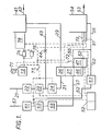
- a pipe 21 carrying hot water from the supply main of a district heating system into a dwelling.
- the pipe 21 connects the hot water from the district heating system to a filter 22 and thence to a temperature sensor 23. From the temperature sensor 23 the pipe leads through a normally closed solenoid valve 24 to a positive displacement device constituted by a hydraulic motor 26.
- the motor 26 co-operates with a second positive displacement device constituted by a hydraulic pump 27 (Figs. 2 and 3).
- the motor 26 and pump 27 each have three cylinders; one cylinder 28 of the motor 26 and one cylinder 29 of the pump 27 are shown in Figs. 2 and 3.
- Pistons 31 and 32 slide in the cylinders 28 and 29 respectively, pressure-tight seals being obtained by the use of cup washers, '0' rings or piston rings (not shown).
- the pistons 31 and 32 are connected together rigidly by a member 33, which is connected by a pair of connecting rods 34 to a crankshaft 36.
- the pistons of the other two cylinders of the motor 26 are similarly connected rigidly to corresponding pistons of the pump 27 by members 33, and the three members 33 are connected to the crankshaft 36 by connecting rods 34, in similar manner to that shown in Figs. 2 and 3.
- the motor 26 and pump 27 have valves to permit the entry and exit of fluid to and from the cylinders 28 and 29.
- the valves of the pump 27 (not shown) are conventional automatic valves.
- the motor 26 has valves 37 operated by cams 38 carried by the crankshaft 36.
- the pipe 21 (Fig. 1) is connected to the inlet valve of the motor 26, and a pipe 39 leads from the exhaust valve of the motor 26 to a hot water buffer tank 41.
- a pipe 42 connects the tank 41 to the heating system of the dwelling, which consists of a number of radiators (not shown) and an indirect coil in a tank for heating the domestic hot water.
- a pipe 43 normally closed by a stop cock 44, connects the pipe 21 to the tank 41 as shown in Fig. 1.
- the motor 26 and pump 27 have a common crankcase 46 (Fig. 1) on which is mounted an electric motor 47.
- the electric motor 47 is a constant speed squirrel cage induction motor.
- the electric motor 47 is connected to the crankshaft 36 of the hydraulic motor 26 and pump 27 by gearing such as a worm and pinion gear, which allows the motor 47 to drive the crankshaft 36, but which does not transmit torque in the other direction and so does not allow the crankshaft 36 to rotate unless the motor 47 is also rotating.
- the motor 47 (Fig. 4) has a shaft 48 which rotates with the motor 47 and carries a disc 49 formed with a slot 51.
- a photo-electric transducer 52 interacts with the slot 51 in the disc 49 to generate a pulse at each revolution of the motor 47.
- a return pipe 53 leads from the heating system of the dwelling to a warm water buffer tank 54.
- a pipe 56 connects the tank 54 to the inlet valve of the pump 27.
- the exhaust valve of the pump 27 is connected by a pipe 57 through a non-return valve 58, a temperature sensor 59 and a normally closed solenoid valve 61 back to the return main of the district heating system.
- a filter (not shown) would be provided between the pipe 57 and the return main.
- a pipe 62 normally closed by a solenoid valve 63, provides a fluid connection as shown in Fig. 1 between the tank 54 and the pipe 57 at a point between the sensor 59 and the valve 61.
- the pipe 62 includes a restrictor (not shown) to restrict the flow of water through it to a low rate even when the valve 63 is open.
- Fig. 5 shows detail of the connections between the two buffer tanks 41 and 54 which, for clarity, are not shown in Fig. 1.
- the tanks 41 and 54 have air spaces in their uppermost portions, these air spaces communicating with each other through a pipe 64.
- the pipe 64 communicates with a chamber 66.
- the upper wall of the chamber 66 is a flexible rubber membrane 67, which is normally in a collapsed condition as shown in Fig. 5 but which can expand to a taut condition to increase the volume of the chamber 66 if the air or the water in the tanks 41 and 54 should expand.
- the chamber 66 is connected through a water-filled U-trap 68 to an overflow pipe 69.
- the presence of the membrane 67 and the U-trap 68 prevent the access of oxygen to the water in the system.
- air can move between the tanks 41 and 54 through the pipe 64 to compensate for varying water levels in the tanks 41 and 54 as water moves through the apparatus and through the heating system of the dwelling. Changes in total system volume, for instance caused by thermal expansion of both air and water, or by inequalities of water entering the system from that leaving the system, are accommodated by expansion or contraction of the membrane 67 of the chamber 66.
- the pipe 69 provides an overflow in case of emergency.
- An AC power supply 71 is connected through relay contacts 72 to the motor 47, electrical connections being shown by broken lines in Fig. 1.
- the power supply 71 also powers a DC power supply 73.
- the DC power supply 73 has connected to it a relay coil 74 which operates the relay contacts 72.
- a slugged relay coil 76 is connected in parallel with the relay coil 74 and controls relay contacts 77.
- the relay contacts 77 as shown in Fig. 1, control the supply of power to the solenoid valves 24 and 61 from the DC power supply 73.
- the tank 41 is fitted with a float switch 78.
- the float switch 78 has a large hysteresis and is arranged to close when the water level in the tank 41 falls to a predetermined low point, and to open when the water level in the tank 41 rises to a predetermined high point.
- the tank 54 is fitted with a low level float switch 79 and an emergency level float switch 81.
- the switch 79 is connected between the power supply 73 and the solenoid valve 63. If the water level in the tank 54 falls to that of the switch 79, the switch 79 closes, supplying power to the solenoid valve 63 and causing the valve 63 to open. If the water level is above that of the switch 79, the switch 79 opens, allowing the valve 63 to close.
- the switch 81 is connected in series between the power supply 73 and the large hysteresis float switch 78. Provided the water level in the tank 54 is above the switch 81, the switch 81 remains closed, and current from the power supply 73 can flow to the float switch 78. When the float switch 78 is closed, the current from the power supply 73 can pass through the switch 78 to the relay coils 74 and 76, causing the relay contacts 72 and 77 to close and power to be supplied to the motor 47 and the solenoid valves 24 and 61, causing the motor 47 to start rotating and the solenoid valves 24 and 61 to open.
- the switch 81 opens and current from the power supply 73 cannot reach the float switch 78. Hence no current can reach the relay coils 74 and 76, the relay contacts 72 and 77 remain open and power is cut off from the electric motor 47, which cannot rotate, and from the solenoid valves 24 and 61, which close.
- a counter and multiplier 82 is connected electrically to the temperature sensors 23 and 59, and to the photoelectric transducer 52.
- the operation of the apparatus is as follows.
- Hot water from the supply main of the district heating system is connected to the pipe 21. Initially the tanks 41 and 54 are empty and the float switch 81 is therefore open. Hence the electric motor 47 cannot rotate and the valves 24 and 61 remain closed, isolating the apparatus from the district heating system.
- the motor 26 and the pump 27 are held stationary by the fact that the electric motor 47 is stationary.
- the worm and pinion gearing (not shown) between the motor 47 and the crankshaft 36 (Fig. 3) prevents the motor 26 and pump 27 from moving when the electric motor 47 is stationary.
- the stop cock 44 is opened manually, allowing hot water to flow from the pipe 21 into the tank 41 and thence to the heating system of the dwelling and the tank 54. Once the apparatus has been adequately filled with hot. water, the stop cock 44 is closed. The water level in the tank 54 being then above the level of the switch 81, the switch 81 is closed and the power supply 73 is connected to the switch 78 through the switch 81. Initially, the switch 78 is closed and the relay coils 74 and 76 are energised, hence the relay contacts 72 are closed and supply current to the electric motor 47, and the relay contacts 77 are closed and supply current to the valves 24 and 61 to hold them open.
- Hot water at high pressure from the district heating system therefore passes through the pipe 21 to the hydraulic motor 26.
- the incoming water does work on the motor 26 and drives the motor 26 and the pump 27.
- the speed of rotation of the motor 26 and pump 27 is controlled and kept constant by the electric motor 47 which is geared to them and which runs at a constant speed.
- the work done by the water on the motor 26 reduces the water pressure. After leaving the motor 26 the water passes through the pipe 39 to the tank 41, which is unpressurized.
- the counter and multiplier 82 receives information from the transducer 52 concerning the number of revolutions of the motor 47. Since the motor 47 is geared to the crankshaft 36 of the hydraulic motor 26 and pump 27, the number of revolutions of the motor 47 gives a measure of the volume of water passing through the domestic heating system. The hydraulic motor 26 and pump 27 are positive displacement devices and therefore deliver an accurate volume of water with each revolution.
- the counter and multiplier 82 also receives information from the temperature sensors 23 and 59 concerning the temperatures of the water at entry to and exit from the apparatus. The counter and multiplier 82 therefore receives sufficient information to allow metering of the quantities of hot water, and of heat, used by the dwelling.
- the hydraulic motor 26 delivers water to the tank 41, which therefore tends to fill, while the pump 27 draws water from the tank 54, which tends to empty. If the heating load in the dwelling is large, the tank 41 will fill only slowly, whereas if the heating load is small the tank 41 will fill relatively quickly. In either case there will come a time when the tank 41 has filled to its pre- determined high point. At this moment, the float switch 78 opens, thus de-activating the relay coil 74 and the slugged relay coil 76.
- the de-activation of the relay coil 74 causes relay contacts 72 to open. Therefore the electric motor 47 decelerates to rest. This causes the hydraulic motor 26 and the pump 27 also to decelerate to rest. No further water is delivered to the tank 41 by the motor 26, nor is further water drawn from the tank 54 by the pump 27.
- relay coil 76 Since the relay coil 76 is slugged, its deactivation is delayed and takes effect after that of the relay coil 74. The deactivation of the relay coil 76 causes the relay contacts 77 to open, thus de-energising the solenoid valves 24 and 61 and causing them to close. The closing of the valves 24 and 61 therefore takes place after the motor 47 has stopped, thus avoiding hydraulic hammer.
- the float switch 78 closes, activating the relay coil 74 and the slugged relay coil 76.
- the relay coil 74 closes the contacts 72, switching on the motor 47.
- the slugged relay coil 76 closes the contacts 77, thus energising and opening the solenoid valves 24 and 61. Hot water is then once again allowed to enter the apparatus from the district heating system and passes through the hydraulic motor 26 to the tank 41 and the cycle begins again.
- the switch 81 When the water level in the tank 54 falls to that of the switch 81, the switch 81 opens, cutting off power to the switch 78 and hence to the relay coils 74 and 76. The relay contacts 72 and 77 therefore open, switching off the motor 47 and de-energising the solenoid valves 24 and 61 and causing them to close. Entry of further hot water to the apparatus from the district heating system is thus prevented. The apparatus is locked stationary until additional water is admitted to it by means of the manual stop cock 44. This would not be done until the leak had been located and cured.
- the solenoid valves 24 and 61 would close so that no water could enter or leave the apparatus.
- the electric motor 47 would stop and with it the hydraulic motor 26 and pump 27, so that no water could pass through the motor 26 or the pump 27.
- the water in the tank 41 would drain by gravity through the heating system of the dwelling into the tank 54.
- Means are provided to prevent the tank 54 from overflowing into the dwelling under these circumstances. This could be done by arranging for the tank 54 to be of sufficiently large capacity to contain all the water that would drain from the tank 41 and the heating system of the dwelling.
- a solenoid valve (normally closed) could be provided in the pipe 53 close to the tank 54. With the electricity supply working, the solenoid valve would be open, but if the electricity failed, the solenoid valve would close and prevent overflow.
- a conventional overflow pipe could be provided for the tank 54, to carry any overflowing water away harmlessly.
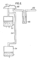
- Fig. 6 shows a device which can be used in place of the buffer tanks 41 and 54 if, for example, a domestic environment makes it difficult to provide a suitable gravity head between the tank 41 and the tank 54, or if a greater pressure is needed than can be provided by gravity.
- a cylinder 91 is divided into two halves by a central plate 92.
- a piston rod 93 is mounted for sliding movement through the plate 92 and carries pistons 94 and 96 at its ends.
- the pistons 94 and 96 are connected to the plate 92 by constant force springs 97 which apply a constant upward biasing force to the assembly of the pistons 94 and 96 and the piston rod 93.
- constant force springs 97 which apply a constant upward biasing force to the assembly of the pistons 94 and 96 and the piston rod 93.
- Flexator Registered Trade Mark
- Tensator Registered Trade Mark
- the piston 94 carries a Bellofram (Registered Trade Mark) rolling diaphragm 98 which provides a leak-proof seal against the cylinder 91 as the piston 94 moves up and down within the cylinder 91.
- the diaphragm 98 and the cylinder 91 define a chamber 99 of variable volume.
- a pipe 101 connects the chamber 99 to the output side of the hydraulic motor 26 (Fig. 1).
- the piston 96 similarly carries a Bellofram rolling diaphragm 102 which provides a leak-proof seal against the lower part of the cylinder 91, as shown, and with the cylinder 91 defines a chamber 103 of variable volume.
- a pipe 104 connects the chamber 103 to the input side of the hydraulic pump 27 (Fig. 1).
- a further pipe 106 connects the chamber 103 to another chamber 107 of variable volume defined by a cylinder 108 and a Bellofram rolling diaphragm 109 carried by a piston 111 and providing a leak-proof seal against the cylinder 108 as the piston 111 moves up and down within the cylinder 108.
- the piston 111 carries a piston rod 112 which is loosely guided within a pipe 110 to allow vertical sliding movement of the piston 111 and piston rod 112.
- the piston rod 112 has a step 113 formed in it, as shown.
- An upper switch 114 and a lower switch 116 are positioned beside the piston rod 112, as shown, and have plungers 117 which are biased to the left, as seen in Fig. 6, against the piston rod 112.
- the switch 114 is open when its plunger 117 is pushed to the right, as seen in Fig. 6.
- the switch 116 is closed when its plugner 117 is pushed to the right.
- the plungers 117 of the switches 114 and 116 are successively allowed to move to the left by the presence of the step 113. This has the effect, successively, of closing the switch 114 and opening the switch 116.
- the piston rod 93 has a slot 115 cut in it, with a shoulder 118 at its upper end and a shoulder 119 at its lower end.
- a toggle switch 121 is resiliently mounted on the plate 92 and has an operating lever 122 which projects into the.slot 115 in the piston rod 93.
- the shoulders 119 and 118 contact the lever 122 of the switch 121 and thereby cause the switch 121 to change its state.
- the shoulder 119 raises the lever 122 to close the switch 121
- the shoulder 118 depresses the lever 122 to open the switch 121.
- the pipe 110 connects a chamber 123 above the piston 111 to a cold water header tank of the dwelling.
- the device shown in Fig. 6 replaces the tanks 41 and 54 shown in Fig. 1 and operates in conjunction with the rest of the apparatus shown in Fig. 1 in the following manner.
- the chamber 99 corresponds to the tank 41 shown in Fig. 1 and is connected to the output side of the hydraulic motor 26 through the pipe 101 and to the input side of the heating system of the dwelling through a pipe (not shown) corresponding to the pipe 42 in Fig. 1.
- the chamber 103 corresponds to the tank 54 shown in Fig. 1 and is connected to the input side of the hydraulic pump 27 through the pipe 104 and to the output side of the heating system of the dwelling through a pipe (not shown) corresponding to the pipe 53 in Fig. 1.
- the chamber 123 contains cold water at a low pressure imposed by the header tank of the dwelling. This low pressure is transmitted through the diaphragm 109 to the chamber 107 and thence to the chamber 103.
- the chamber 103 corresponding to the tank 54 is, therefore, at a low pressure, while the chamber 99 corresponding to the tank 41 is at a higher pressure, the difference between the two pressures being determined by the forces exerted by the springs 97.
- This difference in pressure between the chambers 99 and 103 propels the hot water through the heating system of the dwelling, and therefore corresponds to the difference in height between the tank 41 and the tank 54 in Fig. 1.
- the switch 121 corresponds to the large hysteresis float switch 78 in Fig. 1.
- the piston rod 93 is lowered. In due course it is lowered to the point where the shoulder 118 depresses the lever 122 and changes the state of the switch 121.
- the switch 121 is connected to the remainder of the apparatus in the same way as the switch 78 in Fig. 1, and opening the switch 121 has the same effect of switching off the electric motor 47 and closing the solenoid valves 24 and 61.
- the motor 26 then stops delivering water to the chamber 99, and under the pressure exerted by the springs 97 water passes from the chamber 99 through the heating system of the dwelling and into the chamber 103.
- the piston rod 93 therefore rises. In due course it reaches the point where the shoulder 119 contacts the lever 122 and closes the switch 121. This has the same effect as closing the switch 78 in Fig. 1, and switches on the electric motor 47 and opens the solenoid valves 24 and 61.
- the upper switch 114 in the chamber 123 corresponds to the low level float switch 79 in Fig. 1 and is connected to the remainder of the apparatus in the same way.
- the lower switch 116 corresponds to the emergency level float switch 81 and is connected to the remainder of the apparatus in the same way.
- the switch 114 is normally open, but if the amount of water in the chambers 103 and 107 falls to a pre- determined low point, the piston rod 112 drops to a position where the plunger 117 of the switch 114 passes over the step 113 in the piston rod 112 and the switch 114 closes. This has the same effect as closing the switch 79 in Fig. 1, and opens the solenoid valve 63, thus allowing water from the pipe 62 to flow into the chamber 103.
- the water level in the chambers 103 and 107 falls beyond the predetermined low point to an emergency level, and the piston rod 112 drops to a position where the plunger 117 of the switch 116 passes over the step 113 in the piston rod 1.12.
- the switch 116 then opens. This has the same effect as opening the switch 81 in Fig. 1, and cuts off power to the switch 78 and hence to the relay coils 74 and 76.
- the relay contacts 72 and 77 therefore open, switching off the motor 47 and de-energising the solenoid valves 24 and 61 causing them to close and thereby prevent water from entering or leaving the apparatus from or to the district heating system, until the leak has been located and repaired.
- a constant force spring could be used to exert a downward force on piston 111.
- means are provided for monitoring the amount of time that the valve 63 (Fig. 1) is open and so detecting a slow leak from the apparatus. If desired, these monitoring means can receive information also from the temperature sensors 23 and 59, and /or from other temperature sensors placed elsewhere in the system, and so can determine with great precision the amount of time that the valve 63 should be open in the absence of any leak.
- the monitoring means could also detect leaks into the apparatus, e.g. a leak of untreated water into an indirect heating coil for domestic hot water. A small leak of this kind would result in the valve 63 being open for less time than normal, and the monitoring means could detect this if necessary with great precision in conjunction with temperature sensors. A large leak into the apparatus would cause a rapid rise of water level in the tank 54. This could be stopped by means of a high level float switch in the tank 54 in series between the switches 81 and 78 and arranged to open if the water level reached it, thereby cutting off power from the switch 78 and closing the system down.
- Fig. 7 shows a schematic view of an alternative heating system.
- Hot water from a combined heat and power unit, or from a district heating boiler flows into the heating system along a pipe 131 in the direction of the arrow, and passes through a filter (not shown) and a solenoid valve 132 to a positive displacement motor 133.
- the hot water then passes through a flow control valve 134 to the heating system of a dwelling, represented schematically in Fig. 7 by a single radiator 135.
- From there the water passes through a flow control valve 136 and another filter (not shown) to a positive displacement pump 137, and thence through a non-return valve 130 and a solenoid valve (not shown) and back to the combined heat and power unit or district heating boiler.
- a pressure relief valve 139 may be connected across the radiator 135. Alternatively the valve 139 and its connections can be omitted.
- the motor 133 and pump 137 are mounted on rotary shafts which are connected to an epicyclic gear train 141, the motor 133 being connected to the sun wheel and the pump 137 being connected to the planet wheels.
- the annulus of the epicyclic gear train 141 has teeth on its outside as well as on its inside, and these outside teeth mesh with a gear wheel driven by a variable speed electric motor 142.
- a further variable speed electric motor 143 is connected through a worm 144 and pinion 146 to the shaft of the motor 133.
- the speeds of the electric motors 143 and 142 are controlled by solid state speed controls 147 and 148 respectively.
- the speed controls 147 and 148 are respectively connected to pressure detectors and reservoirs 151 and 149 on the inlet side and 152 and 153 on the outlet side.
- a safety valve 154 is provided on the inlet side as shown.
- Temperature sensors 156 and 157 are provided on the inlet and outlet sides respectively, and are connected to an integration unit 158.
- the integration unit 158 thus receives information about the inlet and outlet temperatures from the sensors 156 and 157; it is also connected to the motor 143 and thus received information about the flow rate through the system.
- a heat meter 159 is connected to the integration unit 158 and measures the heat supplied to the dwelling.
- a flow meter 161 records the flow of water through the system.
- the flow meter 161 incorporates a flow limiting device and a trip mechanism.
- the flow limiting device limits the speed of rotation of the electric motor 143, and hence limits the maximum flow of water through the apparatus.
- the trip mechanism is arranged to stop the motor 133 under fault condition, thereby locking the motor 133 and preventing any further flow of water into the apparatus.
- the operation of the apparatus shown in Fig. 7 is as follows. Water at high pressure enters the system along the pipe 131 and drives the motor 133.
- the motor 133 drives the pump 137 through the epicyclic gear 141.
- the motor 133 reduces the pressure in the water from the high pressure at which it enters the system down to a pre-determined low pressure suitable for a domestic environment. The amount of pressure reduction depends on the magnitude of the braking effect applied to the motor 133 by the electric motor 143 and hence on the speed of revolution of the electric motor 143.
- the speed of the electric motor-143 is controlled by the speed control 147 in response to signals from the pressure detector 151. This arrangement allows complete control of the pressure in the system down-stream of the motor 133 through variation in the speed of revolution of the electric motor 143.
- the function of the pump 137 is to raise the water pressure from the low value present in the domestic system to the higher value suitable for the return main to the central boiler or power station.
- the amount of pressure increase depends on the speed of rotation of the pump 137.
- the pump 137 is driven by the motor 133 through the epicyclic gear train 141 and the speed of revolution of the pump 137 compared to that of the motor 133 is therefore controlled by the speed of rotation of the electric motor 142.
- Rotation of the electric motor 142 is controlled by the speed control 148 in response to signals from the pressure detector 152 upstream of the pump 137. This arrangement controls the speed of rotation of the pump 137 in response to the pressure upstream of the pump 137 and thereby ensures that the necessary higher pressure downstream of the pump 137 is attained.
- the apparatus described therefore, allows complete control of pressure at both the inlet and the outlet of a domestic system, by virtue of the response of the electric motors 142 and 143 to the pressure detectors 151 and 152.
- the work done by the motor 133 in overcoming the losses in the worm and pinion 144 and 146 and the losses in the epicyclic gear train 141, and in driving the pump 137 will be enough to reduce the incoming pressure to the pre-determined low pressure required for the domestic environment.
- no braking effort would be required from the electric motor 143 and the rotation of the motor 143 would be in synchronism, through the worm 144 and the pinion 146, with the shaft of the motor 133.
- the pump 137 At the outlet end of the domestic system, the pump 137, as already explained, is arranged to raise the water pressure. Under some circumstances, the speed at which the pump 137 is driven by the epicyclic gear train 141 (with the electric motor 142 stationary) will be enough to raise the water pressure from a low domestic value to a high value appropriate to the return main. In that case, no movement of the electric motor 142 is required. However, changes in the rotational speed of the motor 133, or changes in water pressure, would alter this situation and would necessitate changes in rotational speed of the pump 137 to maintain the pressure down- stream of the pump 137 at the correct value. Control of the pump 137 is achieved through the pressure sensor 152 and the speed controller 148, as already explained, and the arrangement is such that the rotational speed of the pump 137 varies so as to maintain the pressure downstream of the pump 137 at the correct value.
- a further function of the electric motor 142 applies during start-up or during conditions of low flow through the apparatus. Where the pressure difference between inlet and outlet is considerable, and where the volume flow is large, no difficulty would be experienced, but under low flow or start-up conditions the leakage through the motor 133 and/or the pump 137 might be such as to prevent the device starting. This could be overcome by using a pump 137 with larger capacity than the motor 133, the motor 133 having a small bypass valve across it. In the embodiment illustrated, however, the problem can be overcome very simply by use of the electric motor 142 to drive the pump 137 faster than the motor 133.
- the valve 139 is not essential in view of the inclusion of the reservoirs 149 and 153. However, if these reservoirs were dispensed with, the valve 139 provides an intermittent path between the motor 133 and the pump 137 to deal with leakage past the motor 133 under conditions of no, or low, flow.
- the valve 139 is spring-loaded and is set to open at a pre-determined pressure difference across it.
- a spring-loaded, re-settable valve 154 of the safety valve type, is arranged to allow discharge of water to waste in case of excessive surges of pressure.
- the electric motor 143 would incorporate a pawl and ratchet mechanism such that it is locked, and will not rotate, if the electricity supply fails.
- spring-loaded solenoid valves set to close on failure of the electricity supply, could be located in series with the valves 132 and 130.
- the apparatus described In addition to operating as a pressure controller, the apparatus described also operates as a heat meter, a flow meter, and a flow limiter.
- the integration unit 158 receives signals from the temperature sensors 156 and 157 giving the outlet and inlet temperatures, and from the motor 143 giving the flow rate. This enables the heat meter 159 and the flow meter 161 to be actuated.
- a flow limiting device is incorporated, in that the pressure sensor 151 if it detects a drop in pressure after the pre-determined maximum flow rate (as permitted by the governor of the motor 143 has been attained, is arranged to shut down the system by locking the motor 133. Such a drop in pressure would indicate a leak and therefore the shutting down of the system would prevent the further escape of water through the leak.
- the flow rate also has a pre-determined maximum value when the system is working normally, since the maximum flow through the system is limited by the governor of the motor 143.
- Means are provided for detecting any such abnormal difference in rotational speeds and, on such detection, for stopping the electric motors 142 and 143, thereby locking the motor 133 and the pump 137, and closing solenoid valves in the pipes leading to and from the apparatus.
- the electric motor 143 could be coupled directly to the motor 133 and used as a brake and speed control of the motor 133. Electric control of the motor 143 would be used to achieve control of the motor 133. A pawl and ratchet mechanism would be incorporated such that the motor 133 would be brought to a halt in case of electricity supply failure.
- An important advantage of the various embodiments described is its ability to control the pressures which exist throughout a system.
- the water in a district heating system is at a high pressure of perhaps several tens of bars and must be reduced to a much lower pressure, no more than 3 to 4 bar, to pass through radiators in a dwelling.
- the differential pressure within the dwelling must be at a specific value, say 0.2 bar, to operate the domestic heating satisfactorily.
- the water leaving the domestic heating system is at a low pressure and must be raised to a much higher pressure before it can enter the return main of the district heating system.
- the main system distribution pumps might boost the supply main pressure to as much as 16 bars.
- the supply main pressure might have dropped to 10 bars.
- the apparatus described is capable of accepting it, of dropping the pressure to a suitable value for a consumer's dwelling, say 1.5 bars, of maintaining a desired constant value, say 0.5 bars, across the heating system of a consumer's dwelling, and finally of boosting the pressure of water leaving the consumer's dwelling back up to any desired value, say 9 bars, suitable for the return main of the district heating system.
- the apparatus is capable of generating from these pressures any two other desired pressures at input to and output from the domestic heating system of the consumer.
- the apparatus is capable of generating any desired average pressure between the consumer's input and output and any desired differential pressure between the consumer's input and output.
- the effect of the apparatus described is to provide a barrier between the high pressures commonly employed in district heating systems and the low pressures suitable for a consumer's dwelling. Since positive displacement devices are employed, they provide a complete barrier between the high and low pressure sides. This is an important safety feature.
- the differential pressure at high pressures which exists on the high pressure side and which is used to drive the hot water round the district heating system is transformed to a differential pressure at low pressures on the consumer's side, and is stored on the consumer's side in this form.
- the apparatus described therefore allows direct connection of a district heating main to consumer's dwellings, while controlling the pressures throughout the system and ensuring complete safety. This is an important advantage, because such direct connection of the district heating main is greatly preferable to alternative methods of connection such as indirect connection through heat exchangers or a so-called direct mixing connection which involves mixing of outwardly flowing water with returning water.
- the apparatus described is fail-safe and cannot run out of control.
- the maximum flow rate of water through the apparatus can be controlled, e.g. by the governor of the motor 143 in Fig. 7. Any burst or leak into and out of the apparatus can be detected and controlled.
- the apparatus In the case of a large leak, the apparatus is automatically locked stationary and is isolated from the district heating system by solenoid valves.
- the use of positive displacement devices makes for very low leakage through the positive displacement motor and pump. This means that the apparatus can perform very accurate metering of the fluid passing through it, for example with an error in volume terms of as little as plus or minus 0.03% of the volume of fluid passing through it. This metering of the fluid volume can be combined with measurement of input and output temperatures to give the mass of fluid passing through and the amount of heat extracted from the fluid.
- the apparatus provides, the pressures within a particular installation can be lowered.
- This makes for easier and less expensive methods of manufacture of components, and the ability to use low cost materials, such as plastics, for components and pipework. This can reduce the frictional losses compared to metal components.
- the ability of the apparatus to provide controlled low pressures at consumers' dwellings means that existing radiators and pipework in the dwellings can be used, without the need to replace them with new equipment capable of withstanding high pressure.
- the concept of using two positive displacement devices linked together is put into practice by arranging for incoming water at high pressure from a district heating system to enter first a positive displacement motor.
- the motor reduces the pressure in the water to a suitable level for a domestic heating system.
- a positive displacement pump linked to the motor then raises the pressure of water leaving the domestic system to a value suitable for returning the water to the return main of the district heating system.
- both of the two positive displacement devices are pumps. Water from the supply main enters the apparatus and is pumped onwards by the first positive displacement device. In due course the water reaches the second positive displacement device and is pumped by it into the return main.
- the two pumps are linked together and driven by a single source of power.
- both of the two positive displacement devices can be motors. In this case the effect of both of them would be to reduce the pressure in a stream of fluid.
- the normal arrangement would be for the return pressure from the apparatus to be lower than the incoming pressure.
- the incoming pressure from a district heating main might be 10 bars, as described above, and the return main pressure might be 9 bars.
- the return pressure from such a motorised version of the apparatus can be higher than the incoming pressure.
- a district heating system were required to serve 100,000 consumers, it would be possible to drive the hot water around the network by means of a number of identical motorised versions of the apparatus. 1,000 such motorised versions might be sufficient.
- 1,000 much smaller pumps constituted by motorised versions of the apparatus could be employed. This would result in a substantial energy saving, and would avoid the need for very high pressures close to a single very large main system distribution pump.
- the apparatus described in fact, is capable of reducing the pressure of fluid passing through it, or of increasing the said pressure, or of maintaining the said pressure constant.
- the positive displacement pump receives the incoming water and does work on it to boost it to a higher pressure. Later, the water passes to the positive displacement motor, where it does work on the motor and its pressure is consequently reduced.
- This embodiment could be used, for example, for connecting a district heating system to a tall building. Incoming water from the supply main is boosted in pressure by the positive displacement pump to pump it to the top of the building. After passing through the heating systems of the consumers in the building, the water returns to the bottom of the building, by which time it will be at a high pressure because of the gravity head imposed on it. It passes to the positive displacement pump, which reduces the water pressure and makes use of this pressure to drive the pump.
- Figs. 1-6 differs substantially from that of Fig. 7 in that the motor 26 and the pump 27 are constrained by the electric motor 47 to rotate at only one speed, control of the passage of water through the apparatus being achieved by starting and stopping the motor 26 and pump 27 rather than by varying their speed. This has an important advantage, explained below, particularly for small installations.
- Fig. 7 For large installations, however, it is desirable ta have continuously variable pump and motor speeds, in order to give better flexibility. For such large installations the embodiment of Fig. 7 would be suitable.
- the advantage conferred by the single speed of the electric motor 47, and hence of the motor 26 and pump 27, is that the turn-down problem is eliminated. If there is a requirement to meter a fluid at a variety of different flow rates, the accuracy of metering suffers. The inaccuracy results from leakage, and the leakage of a metering device is constant both at low and high flow rates. Therefore, at low flow rates the leakage has a much bigger effect on the accuracy of metering than it does at high flow rates. It is difficult, therefore, to provide accurate metering at a variety of different flow rates.
- the direct coupling together of the pistons 31 of the motor 26 and the pistons 32 of the pump 27 has the effect of reducing frictional and other losses, since the net force acting on the composite of one of the pistons 31 and one of the pistons 32 is the difference between the individual forces acting on each of the pistons separately.
- the seatings for the valves can be made slightly resilient.
- the motor 26 and pump 27 are positive displacement devices and have been described above as having pistons and cylinders. Any other form of positive displacement device, however, could be used in any of the embodiments, such as a geared device (e.g. of the Roots blower type), a vaned device, a piston device of the swash plate or radial piston type, a peristaltic device, a Wank- el-type device, or any other desired form of device which is a positive displacement device.
- a geared device e.g. of the Roots blower type
- a vaned device e.g. of the Roots blower type
- a vaned device e.g. of the Roots blower type
- piston device of the swash plate or radial piston type e.g. of the Roots blower type
- a peristaltic device e.g. of the a peristaltic device
- Wank- el-type device e.g. of the Wank-
- the function of the motor 26 and the function of the pump 27 could be performed by a single device.
- a set of radial vanes mounted on a central rotary shaft could rotate in a casing divided into two parts, each part having an inlet and an outlet.
- the fluid entering through the inlet and leaving through the outlet could do work on the vanes, so rotating the shaft.
- the vanes could do work on the fluid. Therefore, in the said one part of the casing, the device constitutes a positive displacement motor, and in the said other part of the casing, it constitutes a pump.
- the apparatus is suitable for controlling the flow and the pressure of hot water in district heating systems. It could also be used for controlling the flow and/or the pressure of fluids other than water, or of water or other fluids for purposes other than heating, although such uses or purposes form no part of the present invention as defined by the appended claims.
- the pistons 31 and 32 of Figs. 2 and 3 are replaced by an arrangement in which movable members corresponding to the pistons 31 and 32 are sealed within the positive displacement device constituted by the pump 26 and the motor 27.
- the sealing is performed by movable walls joining the movable members to fixed parts of the pump 26 and motor 27, these fixed parts corresponding to the cylinders 28 and 29.
- the pistons 31 and 32 could be replaced by diaphragms.
- movable members corresponding to the pistons 31 and 32 could be joined by bellows to fixed parts of the pump 26 and motor 27 corresponding to the cylinders 28 and 29.
- BELLOFRAM Registered Trade Mark rolling diaphragms could be used.
Landscapes
- Engineering & Computer Science (AREA)
- Mechanical Engineering (AREA)
- General Engineering & Computer Science (AREA)
- Physics & Mathematics (AREA)
- Chemical & Material Sciences (AREA)
- Combustion & Propulsion (AREA)
- Thermal Sciences (AREA)
- General Physics & Mathematics (AREA)
- Automation & Control Theory (AREA)
- Steam Or Hot-Water Central Heating Systems (AREA)
- Flow Control (AREA)
- Control Of Fluid Pressure (AREA)
- Paper (AREA)
- Massaging Devices (AREA)
- Domestic Hot-Water Supply Systems And Details Of Heating Systems (AREA)
- Treatment Of Fiber Materials (AREA)
Abstract
Description
- This invention relates to apparatus for controlling the flow of a fluid and in particular to apparatus employing positive displacement devices for controlling the flow of a fluid in a district hot water supply system.
- The term "positive displacement device" is understood to mean a device having an inlet and an outlet and at least one movable member which moves to displace fluid, the arrangement being such that the amount of fluid displaced is proportional to the amount by which the member is moved and that when the member is held stationary, substantially no fluid flows from the inlet to the outlet.
- It is known, for example as described in United Kingdom Patent Specification No. 1595787, and United States Patent Specification No. 4021149, to provide apparatus for controlling flow of a fluid, including two positive displacement devices linked together, one of the devices being driven by the fluid and acting as a motor driving the other positive displacement device, which acts as a pump to drive the fluid through a circulatory system connected to the apparatus.
- With such apparatus it is possible to control the input and output pressures of both positive displacement devices by controlling the speeds at which the devices operate. Thus in the apparatus described in British Patent Specification No. 1595787 two positive displacement devices, controlled by a speed governor, are used to regulate the heat supply to a low pressure hot water system from a high pressure hot water system. This finds practical application in the regulated supply of hot water to a low pressure load (for example, a domestic user) from a high pressure district heating supply main.
- A practical problem to be overcome in such apparatus is that of maintaining a continuous delivery of fluid (for example, water) to a load at a regulated pressure notwithstanding leakages of fluid from the load to which the low pressure fluid is delivered, and in spite of loss of fluid from the load through leakage. It is also desirable that the apparatus should be capable of making up the inevitable loss of fluid which will result if the two positive displacement devices are operated "back-to-back" and displace equal volumes of fluid, where the fluid displaced by one device is at a different temperature from that displaced by the other device: for example in the application to a district hot water heating system referred to above, the return flow of water from the load will be at a lower temperature than the hot water delivered to the load, and will therefore have a slightly higher density. Consequently, the displacement of equal volumes by the two devices will result in a net loss of fluid from the load.
- According to the present invention, there is provided a district hot water supply system in which the supply of water to consumers is controlled by flow control apparatus including a first positive displacement device connected to an input fluid pressure to deliver fluid to a load at a specific load pressure, a second positive displacement device arranged to receive fluid at the load pressure and to deliver fluid at the input pressure, and means to control the speed of at least one of the positive displacement devices to control the flow of fluid through the load and/or the load pressure, characterised in that the first positive displacement device delivers fluid through a first buffer container and the second positive displacement device is connected to the load pressure through a second buffer container.
- The buffer containers serve two useful purposes: in the first place they enable a substantially constant load pressure to be maintained notwithstanding intermittent operation of one or both of the positive displacement devices; secondly they enable the apparatus to compensate for the difference in density of the fluid at the inlet to and outlet from a load, while enabling equal volumes of fluid to be displaced by the two devices.
- In the application of the invention to the regulated supply of hot water to a low pressure load from a high pressure supply of a district heating system the first positive displacement device acts as a motor which is driven, in use, by the fluid at the input pressure, delivering the fluid at a lower pressure to the load, and the second positive displacement device acts as a pump arranged to draw fluid from the load at the said lower pressure and to deliver it at the said input pressure. In this case the incoming fluid flows first through the motor and then through the pump.
- Alternatively, the apparatus may be such that the incoming fluid flows first through a pump comprising the first positive displacement device and then through a motor comprising the second positive displacement device. Such apparatus can be used to pump fluid to a height against gravity, for example to the top of a hill or high building. Also, the apparatus can receive fluid from a height and can reduce the pressure imposed on the fluid by gravity.
- Advantageously means are provided for detecting the amount of movement performed by the movable member of at least one of the positive displacement devices, and means may be provided for measuring fluid temperatures at inlet to and outlet from the apparatus. With this arrangement the amount of heat taken from the fluid can be measured.
- Desirably the apparatus includes means for detecting a leak of fluid from the apparatus. Preferably there are means for locking the apparatus stationary in case of such a leak. Preferably there are also means for preventing fluid from entering or leaving the apparatus in case of such a leak.
- Advantageously means are included for limiting the maximum speed at which at least one of the positive displacement devices can operate.
- Conveniently, the arrangement is such that the movable members of the positive displacement devices operate at a single, constant speed and control of fluid passing through the apparatus is achieved by alternation between operating the members at the said constant speed and keeping them stationary. With this arrangement, the positive displacement devices can be set for maximum accuracy of metering at the said one constant speed and the problem of metering inaccuracies at other speeds does not arise.
- Advantageously, the apparatus includes switching means arranged to cause at least the said one of the positive displacement devices to cease discharging fluid to the first buffer container when a predetermined greater volume of fluid is in the container, but to restart discharging fluid into the said container when a predetermined lesser volume of fluid is in the container.
- Desirably the switching means are arranged to cause the said one of the positive displacement devices to cease discharging fluid and are arranged, after a delay, to cause valves to close to prevent fluid from entering or leaving the apparatus.
- Advantageously the apparatus includes additional switching means arranged to detect the presence of a predetermined small volume of fluid in the second buffer container and to allow additional fluid into the second container when the volume of fluid in it drops to the said pre- determined small volume.
- Desirably the apparatus includes further switching means arranged to detect the presence of a predetermined very slTÍall volume of fluid in the second buffer container and to stop the apparatus from operating when the volume of fluid in the said second container drops to the said predetermined very small volume.
- Conveniently the first buffer container is arranged above the load to deliver fluid to the load under gravity and the second buffer container is arranged below the load to accept fluid from the load under gravity.
- Desirably the first buffer container is air-tight and includes means for allowing its total volume to vary as the amount of fluid in it varies. Conveniently both the containers are air-tight and joined by an air duct through which air moves between them to take up the volumes in them not occupied by the fluid.
- As an alternative to the two containers being arranged at different heights to enable fluid to pass between them under gravity, one or both of the buffer containers may be pressurized. Desirably the pressurisation is by means of a constant force spring acting on a diaphragm. Advantageously both the containers are pressurized to different pressures. Conveniently the two buffer containers are arranged adjacent one another with a movable barrier between them such that as one container increases in volume the other container decreases in volume and vice versa.
- Instead of controlling the passage of fluid through the apparatus by alternation between operating the movable members at the said constant speed and keeping them stationary, the apparatus may include means for varying the speed at which the movable members operate. These may include means for varying the ratio at which the two positive displacement devices are linked together.
- The means for controlling the movable members may include a motor coupled to at least one of the movable members and arranged to vary in speed. Alternatively the motor may be a constant speed motor such as a constant speed electric motor. The coupling between the movable members and the means for controlling the movable members is desirably such that the movable members cannot move if the means for controlling them is stationary. A geared coupling such as a worm and pinion gear is suitable.
- Conveniently a motor is provided which is operatively connected to the link between the two positive displacement devices such that operation of the motor alters the ratio between the two positive displacement devices. The motor may also be arranged to provide power to the apparatus to drive at least one of the positive displacement devices.
- The movable members of the two positive displacement devices are preferably rigidly linked together. With this arrangement frictional losses are reduced. Desirably the positive displacement devices include valves having resilient seats. With this arrangment better sealing is achieved.
- Advantageously the apparatus includes means for sensing and controlling the differential pressure between two points in the apparatus. These means may include a brake for braking one . of the positive displacement devices. Alternatively the means may include means responsive to the pressure at one point in the apparatus to vary the ratio between the two positive displacement devices.
- Conveniently the apparatus includes means for detecting at least one pressure in the apparatus and conveying this information to a remote point. Fibre optics may be used for conveying the information.
- The invention will now be described by way of example with reference to the accompanying drawings, in which:
- Fig. 1 is a block diagram of flow control apparatus according to one embodiment of the invention;
- Fig. 2 is a side elevational view of part of the apparatus of Fig. 1;
- Fig. 3 is a plan view of the apparatus of Fig. 2;
- Fig. 4 is a side elevational view of a motor, being part of the apparatus of Fig. 1;
- Fig. 5 is a side elevation view showing connections between two buffer tanks which are part of the apparatus of Fig. 1;
- Fig. 6 is a side elevational view of an alternative to the apparatus shown in Fig. 5, and
- Fig. 7 is a block diagram of another embodiment of flow control apparatus.
- Referring to the drawings and in particular to Fig. 1, there is shown a
pipe 21 carrying hot water from the supply main of a district heating system into a dwelling. Thepipe 21 connects the hot water from the district heating system to afilter 22 and thence to atemperature sensor 23. From thetemperature sensor 23 the pipe leads through a normally closedsolenoid valve 24 to a positive displacement device constituted by ahydraulic motor 26. - The
motor 26 co-operates with a second positive displacement device constituted by a hydraulic pump 27 (Figs. 2 and 3). Themotor 26 andpump 27 each have three cylinders; onecylinder 28 of themotor 26 and onecylinder 29 of thepump 27 are shown in Figs. 2 and 3.Pistons cylinders pistons member 33, which is connected by a pair of connectingrods 34 to acrankshaft 36. The pistons of the other two cylinders of themotor 26 are similarly connected rigidly to corresponding pistons of thepump 27 bymembers 33, and the threemembers 33 are connected to thecrankshaft 36 by connectingrods 34, in similar manner to that shown in Figs. 2 and 3. - The
motor 26 and pump 27 have valves to permit the entry and exit of fluid to and from thecylinders - The
motor 26 hasvalves 37 operated bycams 38 carried by thecrankshaft 36. The pipe 21 (Fig. 1) is connected to the inlet valve of themotor 26, and apipe 39 leads from the exhaust valve of themotor 26 to a hotwater buffer tank 41. Apipe 42 connects thetank 41 to the heating system of the dwelling, which consists of a number of radiators (not shown) and an indirect coil in a tank for heating the domestic hot water. - A
pipe 43, normally closed by astop cock 44, connects thepipe 21 to thetank 41 as shown in Fig. 1. - The
motor 26 and pump 27 have a common crankcase 46 (Fig. 1) on which is mounted anelectric motor 47. Theelectric motor 47 is a constant speed squirrel cage induction motor. Theelectric motor 47 is connected to thecrankshaft 36 of thehydraulic motor 26 and pump 27 by gearing such as a worm and pinion gear, which allows themotor 47 to drive thecrankshaft 36, but which does not transmit torque in the other direction and so does not allow thecrankshaft 36 to rotate unless themotor 47 is also rotating. - The motor 47 (Fig. 4) has a
shaft 48 which rotates with themotor 47 and carries adisc 49 formed with aslot 51. A photo-electric transducer 52 interacts with theslot 51 in thedisc 49 to generate a pulse at each revolution of themotor 47. - A
return pipe 53 leads from the heating system of the dwelling to a warmwater buffer tank 54. Apipe 56 connects thetank 54 to the inlet valve of thepump 27. The exhaust valve of thepump 27 is connected by apipe 57 through anon-return valve 58, atemperature sensor 59 and a normally closedsolenoid valve 61 back to the return main of the district heating system. A filter (not shown) would be provided between thepipe 57 and the return main. - A
pipe 62, normally closed by asolenoid valve 63, provides a fluid connection as shown in Fig. 1 between thetank 54 and thepipe 57 at a point between thesensor 59 and thevalve 61. Thepipe 62 includes a restrictor (not shown) to restrict the flow of water through it to a low rate even when thevalve 63 is open. - Fig. 5 shows detail of the connections between the two
buffer tanks tanks pipe 64. Thepipe 64 communicates with achamber 66. The upper wall of thechamber 66 is aflexible rubber membrane 67, which is normally in a collapsed condition as shown in Fig. 5 but which can expand to a taut condition to increase the volume of thechamber 66 if the air or the water in thetanks chamber 66 is connected through a water-filled U-trap 68 to anoverflow pipe 69. - The presence of the
membrane 67 and the U-trap 68 prevent the access of oxygen to the water in the system. At the same time, air can move between thetanks pipe 64 to compensate for varying water levels in thetanks membrane 67 of thechamber 66. Thepipe 69 provides an overflow in case of emergency. - An
AC power supply 71 is connected through relay contacts 72 to themotor 47, electrical connections being shown by broken lines in Fig. 1. Thepower supply 71 also powers aDC power supply 73. TheDC power supply 73 has connected to it arelay coil 74 which operates the relay contacts 72. A sluggedrelay coil 76 is connected in parallel with therelay coil 74 and controls relaycontacts 77. Therelay contacts 77, as shown in Fig. 1, control the supply of power to thesolenoid valves DC power supply 73. Thetank 41 is fitted with afloat switch 78. Thefloat switch 78 has a large hysteresis and is arranged to close when the water level in thetank 41 falls to a predetermined low point, and to open when the water level in thetank 41 rises to a predetermined high point. - The
tank 54 is fitted with a lowlevel float switch 79 and an emergencylevel float switch 81. Theswitch 79 is connected between thepower supply 73 and thesolenoid valve 63. If the water level in thetank 54 falls to that of theswitch 79, theswitch 79 closes, supplying power to thesolenoid valve 63 and causing thevalve 63 to open. If the water level is above that of theswitch 79, theswitch 79 opens, allowing thevalve 63 to close. - The
switch 81 is connected in series between thepower supply 73 and the largehysteresis float switch 78. Provided the water level in thetank 54 is above theswitch 81, theswitch 81 remains closed, and current from thepower supply 73 can flow to thefloat switch 78. When thefloat switch 78 is closed, the current from thepower supply 73 can pass through theswitch 78 to the relay coils 74 and 76, causing therelay contacts 72 and 77 to close and power to be supplied to themotor 47 and thesolenoid valves motor 47 to start rotating and thesolenoid valves tank 54 is at or below the level of theswitch 81, theswitch 81 opens and current from thepower supply 73 cannot reach thefloat switch 78. Hence no current can reach the relay coils 74 and 76, therelay contacts 72 and 77 remain open and power is cut off from theelectric motor 47, which cannot rotate, and from thesolenoid valves - A counter and
multiplier 82 is connected electrically to thetemperature sensors photoelectric transducer 52. - The operation of the apparatus is as follows.
- Hot water from the supply main of the district heating system is connected to the
pipe 21. Initially thetanks float switch 81 is therefore open. Hence theelectric motor 47 cannot rotate and thevalves - The
motor 26 and thepump 27 are held stationary by the fact that theelectric motor 47 is stationary. The worm and pinion gearing (not shown) between themotor 47 and the crankshaft 36 (Fig. 3) prevents themotor 26 and pump 27 from moving when theelectric motor 47 is stationary. - To fill the apparatus, the
stop cock 44 is opened manually, allowing hot water to flow from thepipe 21 into thetank 41 and thence to the heating system of the dwelling and thetank 54. Once the apparatus has been adequately filled with hot. water, thestop cock 44 is closed. The water level in thetank 54 being then above the level of theswitch 81, theswitch 81 is closed and thepower supply 73 is connected to theswitch 78 through theswitch 81. Initially, theswitch 78 is closed and the relay coils 74 and 76 are energised, hence the relay contacts 72 are closed and supply current to theelectric motor 47, and therelay contacts 77 are closed and supply current to thevalves - With the
valves motor 47 rotating, hot water from the district heating system is able to enter the apparatus through thepipe 21, to move through the apparatus, and to return to the district heating system through thepipe 57. - Hot water at high pressure from the district heating system therefore passes through the
pipe 21 to thehydraulic motor 26. The incoming water does work on themotor 26 and drives themotor 26 and thepump 27. The speed of rotation of themotor 26 and pump 27 is controlled and kept constant by theelectric motor 47 which is geared to them and which runs at a constant speed. The work done by the water on themotor 26 reduces the water pressure. After leaving themotor 26 the water passes through thepipe 39 to thetank 41, which is unpressurized. - From the
tank 41 the hot water passes by gravity to and through the domestic heating system, and thence through thepipe 53 to thetank 54. Thepump 27 meanwhile rotates and draws water out from thetank 54 through thepipe 56. The water leaves thetank 54 at low pressure and thepump 27 does work upon the water and raises it to a high pressure suitable for connection to the return main of the district heating system. Water therefore leaves thepump 27 at high pressure and passes through thepipe 57 back to the return main via thenon-return valve 58, thetemperature sensor 59 and thesolenoid valve 61. - The counter and
multiplier 82 receives information from thetransducer 52 concerning the number of revolutions of themotor 47. Since themotor 47 is geared to thecrankshaft 36 of thehydraulic motor 26 and pump 27, the number of revolutions of themotor 47 gives a measure of the volume of water passing through the domestic heating system. Thehydraulic motor 26 and pump 27 are positive displacement devices and therefore deliver an accurate volume of water with each revolution. - The counter and
multiplier 82 also receives information from thetemperature sensors multiplier 82 therefore receives sufficient information to allow metering of the quantities of hot water, and of heat, used by the dwelling. - With the apparatus operating as described above, the
hydraulic motor 26 delivers water to thetank 41, which therefore tends to fill, while thepump 27 draws water from thetank 54, which tends to empty. If the heating load in the dwelling is large, thetank 41 will fill only slowly, whereas if the heating load is small thetank 41 will fill relatively quickly. In either case there will come a time when thetank 41 has filled to its pre- determined high point. At this moment, thefloat switch 78 opens, thus de-activating therelay coil 74 and the sluggedrelay coil 76. - The de-activation of the
relay coil 74 causes relay contacts 72 to open. Therefore theelectric motor 47 decelerates to rest. This causes thehydraulic motor 26 and thepump 27 also to decelerate to rest. No further water is delivered to thetank 41 by themotor 26, nor is further water drawn from thetank 54 by thepump 27. - Since the
relay coil 76 is slugged, its deactivation is delayed and takes effect after that of therelay coil 74. The deactivation of therelay coil 76 causes therelay contacts 77 to open, thus de-energising thesolenoid valves valves motor 47 has stopped, thus avoiding hydraulic hammer. - When the
tank 41 has filled to its pre-determined high point, therefore, water is prevented from entering or leaving the apparatus. Water is also prevented from passing through themotor 26 or thepump 27. The water in thetank 41 drains by gravity into thetank 54 via the heating system of the dwelling. - Once the water from the
tank 41 has emptied by this means to its predetermined low point, thefloat switch 78 closes, activating therelay coil 74 and the sluggedrelay coil 76. Therelay coil 74 closes the contacts 72, switching on themotor 47. The sluggedrelay coil 76 closes thecontacts 77, thus energising and opening thesolenoid valves hydraulic motor 26 to thetank 41 and the cycle begins again. - As explained above, when the relay coils 74 and 76 are de-energised, there is a delay in the de- energisation of the slugged
relay coil 76 and hence thevalves motor 47 has stopped. The energisation of a slugged relay coil, however, is immediate, so the relay coils 74 and 76 are energised immediately and thesolenoid valves motor 47 is switched on. - While the
electric motor 47 is rotating, thehydaulic motor 26 and pump 27 rotate together. Their swept volume is the same, so the volume of water admitted by themotor 26 is equal to the volume pumped out by thepump 27. However the water pumped out by thepump 27 has given up heat to the dwelling and is therefore at a lower temerature and hence of a high density. Over a period therefore, a greater mass of water will be pumped out by thepump 27 than is admitted by themotor 26, and the amount of water in the system will gradually decrease. - Eventually the reduced amount of water in the system will be such that the level of water in the
tank 54 drops to the level of the lowlevel float switch 79. Theswitch 79 then closes, providing power to thesolenoid valve 63 and causing thevalve 63 to open. Water from thepipe 57 then flows along thepipe 62 through the restrictor and through theopen valve 63 into thetank 54, restoring the level of water in thetank 54 to above the level of theswitch 79. - If a slow leak developed in the system, water would be lost slowly and the
valve 63 would consequently be opened for an abnormal amount of time to make good the loss. Means are provided (not shown) for monitoring the amount of time that thevalve 63 is open, and so detecting a slow leak from the system. - If a large leak developed in the system, water would be lost rapidly and, even with the
valve 63 permanently open, the flow through thepipe 62 would not be enough to make good the loss. Hence the water level in thetank 54 would fall below the level of the lowlevel float switch 79 and would eventually reach the level of the emergencylevel float switch 81. - When the water level in the
tank 54 falls to that of theswitch 81, theswitch 81 opens, cutting off power to theswitch 78 and hence to the relay coils 74 and 76. Therelay contacts 72 and 77 therefore open, switching off themotor 47 and de-energising thesolenoid valves manual stop cock 44. This would not be done until the leak had been located and cured. - If the apparatus were to cease operating, e.g. as a result of failure of the electricity supply, the
solenoid valves electric motor 47 would stop and with it thehydraulic motor 26 and pump 27, so that no water could pass through themotor 26 or thepump 27. However the water in thetank 41 would drain by gravity through the heating system of the dwelling into thetank 54. - Means are provided to prevent the
tank 54 from overflowing into the dwelling under these circumstances. This could be done by arranging for thetank 54 to be of sufficiently large capacity to contain all the water that would drain from thetank 41 and the heating system of the dwelling. Alternatively, a solenoid valve (normally closed) could be provided in thepipe 53 close to thetank 54. With the electricity supply working, the solenoid valve would be open, but if the electricity failed, the solenoid valve would close and prevent overflow. Alternatively a conventional overflow pipe could be provided for thetank 54, to carry any overflowing water away harmlessly. - Fig. 6 shows a device which can be used in place of the
buffer tanks tank 41 and thetank 54, or if a greater pressure is needed than can be provided by gravity. - A
cylinder 91 is divided into two halves by acentral plate 92. Apiston rod 93 is mounted for sliding movement through theplate 92 and carriespistons 94 and 96 at its ends. Thepistons 94 and 96 are connected to theplate 92 by constant force springs 97 which apply a constant upward biasing force to the assembly of thepistons 94 and 96 and thepiston rod 93. As shown in Fig. 6, there is present one Flexator (Registered Trade Mark) and one Tensator (Registered Trade Mark) constant force spring. It is not necessary to have two such springs, one or both can be present as desired. - The piston 94 carries a Bellofram (Registered Trade Mark) rolling
diaphragm 98 which provides a leak-proof seal against thecylinder 91 as the piston 94 moves up and down within thecylinder 91. Thus thediaphragm 98 and thecylinder 91 define achamber 99 of variable volume. Apipe 101 connects thechamber 99 to the output side of the hydraulic motor 26 (Fig. 1). - The
piston 96 similarly carries aBellofram rolling diaphragm 102 which provides a leak-proof seal against the lower part of thecylinder 91, as shown, and with thecylinder 91 defines achamber 103 of variable volume. Apipe 104 connects thechamber 103 to the input side of the hydraulic pump 27 (Fig. 1). Afurther pipe 106 connects thechamber 103 to anotherchamber 107 of variable volume defined by acylinder 108 and aBellofram rolling diaphragm 109 carried by apiston 111 and providing a leak-proof seal against thecylinder 108 as thepiston 111 moves up and down within thecylinder 108. - The
piston 111 carries apiston rod 112 which is loosely guided within apipe 110 to allow vertical sliding movement of thepiston 111 andpiston rod 112. Thepiston rod 112 has astep 113 formed in it, as shown. Anupper switch 114 and alower switch 116 are positioned beside thepiston rod 112, as shown, and haveplungers 117 which are biased to the left, as seen in Fig. 6, against thepiston rod 112. Theswitch 114 is open when itsplunger 117 is pushed to the right, as seen in Fig. 6. Theswitch 116, however, is closed when itsplugner 117 is pushed to the right. As thepiston 111 andpiston rod 112 slide downwards, as seen in Fig. 6, theplungers 117 of theswitches step 113. This has the effect, successively, of closing theswitch 114 and opening theswitch 116. - The
piston rod 93 has aslot 115 cut in it, with ashoulder 118 at its upper end and ashoulder 119 at its lower end. Atoggle switch 121 is resiliently mounted on theplate 92 and has an operatinglever 122 which projects intothe.slot 115 in thepiston rod 93. As thepiston rod 93 rises and falls, theshoulders lever 122 of theswitch 121 and thereby cause theswitch 121 to change its state. When thepiston rod 93 rises, theshoulder 119 raises thelever 122 to close theswitch 121, and when thepiston rod 93 falls, theshoulder 118 depresses thelever 122 to open theswitch 121. - The
pipe 110 connects achamber 123 above thepiston 111 to a cold water header tank of the dwelling. - The device shown in Fig. 6 replaces the
tanks - The
chamber 99 corresponds to thetank 41 shown in Fig. 1 and is connected to the output side of thehydraulic motor 26 through thepipe 101 and to the input side of the heating system of the dwelling through a pipe (not shown) corresponding to thepipe 42 in Fig. 1. Thechamber 103 corresponds to thetank 54 shown in Fig. 1 and is connected to the input side of thehydraulic pump 27 through thepipe 104 and to the output side of the heating system of the dwelling through a pipe (not shown) corresponding to thepipe 53 in Fig. 1. - The
chamber 123 contains cold water at a low pressure imposed by the header tank of the dwelling. This low pressure is transmitted through thediaphragm 109 to thechamber 107 and thence to thechamber 103. Thechamber 103 corresponding to thetank 54 is, therefore, at a low pressure, while thechamber 99 corresponding to thetank 41 is at a higher pressure, the difference between the two pressures being determined by the forces exerted by thesprings 97. This difference in pressure between thechambers tank 41 and thetank 54 in Fig. 1. - The
switch 121 corresponds to the largehysteresis float switch 78 in Fig. 1. When themotor 26 delivers water to thechamber 99, thepiston rod 93 is lowered. In due course it is lowered to the point where theshoulder 118 depresses thelever 122 and changes the state of theswitch 121. This opens theswitch 121, and corresponds to opening the largehysteresis float switch 78. Theswitch 121 is connected to the remainder of the apparatus in the same way as theswitch 78 in Fig. 1, and opening theswitch 121 has the same effect of switching off theelectric motor 47 and closing thesolenoid valves - The
motor 26 then stops delivering water to thechamber 99, and under the pressure exerted by thesprings 97 water passes from thechamber 99 through the heating system of the dwelling and into thechamber 103. Thepiston rod 93 therefore rises. In due course it reaches the point where theshoulder 119 contacts thelever 122 and closes theswitch 121. This has the same effect as closing theswitch 78 in Fig. 1, and switches on theelectric motor 47 and opens thesolenoid valves - The
upper switch 114 in thechamber 123 corresponds to the lowlevel float switch 79 in Fig. 1 and is connected to the remainder of the apparatus in the same way. Similarly thelower switch 116 corresponds to the emergencylevel float switch 81 and is connected to the remainder of the apparatus in the same way. Thus theswitch 114 is normally open, but if the amount of water in thechambers piston rod 112 drops to a position where theplunger 117 of theswitch 114 passes over thestep 113 in thepiston rod 112 and theswitch 114 closes. This has the same effect as closing theswitch 79 in Fig. 1, and opens thesolenoid valve 63, thus allowing water from thepipe 62 to flow into thechamber 103. - Similarly if a large leak exists in the system, the water level in the
chambers piston rod 112 drops to a position where theplunger 117 of theswitch 116 passes over thestep 113 in the piston rod 1.12. Theswitch 116 then opens. This has the same effect as opening theswitch 81 in Fig. 1, and cuts off power to theswitch 78 and hence to the relay coils 74 and 76. Therelay contacts 72 and 77 therefore open, switching off themotor 47 and de-energising thesolenoid valves - As an alternative to using the header tank of the dwelling to impose a pressure through the
pipe 110 on the upper side of thepiston 111, a constant force spring could be used to exert a downward force onpiston 111. As referred to above, means (not shown) are provided for monitoring the amount of time that the valve 63 (Fig. 1) is open and so detecting a slow leak from the apparatus. If desired, these monitoring means can receive information also from thetemperature sensors valve 63 should be open in the absence of any leak. - In addition to detecting leaks out of the apparatus, the monitoring means could also detect leaks into the apparatus, e.g. a leak of untreated water into an indirect heating coil for domestic hot water. A small leak of this kind would result in the
valve 63 being open for less time than normal, and the monitoring means could detect this if necessary with great precision in conjunction with temperature sensors. A large leak into the apparatus would cause a rapid rise of water level in thetank 54. This could be stopped by means of a high level float switch in thetank 54 in series between theswitches switch 78 and closing the system down. - Fig. 7 shows a schematic view of an alternative heating system. Hot water from a combined heat and power unit, or from a district heating boiler, flows into the heating system along a
pipe 131 in the direction of the arrow, and passes through a filter (not shown) and asolenoid valve 132 to apositive displacement motor 133. The hot water then passes through aflow control valve 134 to the heating system of a dwelling, represented schematically in Fig. 7 by asingle radiator 135. From there the water passes through aflow control valve 136 and another filter (not shown) to apositive displacement pump 137, and thence through a non-return valve 130 and a solenoid valve (not shown) and back to the combined heat and power unit or district heating boiler. Apressure relief valve 139 may be connected across theradiator 135. Alternatively thevalve 139 and its connections can be omitted. - The
motor 133 and pump 137 are mounted on rotary shafts which are connected to anepicyclic gear train 141, themotor 133 being connected to the sun wheel and thepump 137 being connected to the planet wheels. The annulus of theepicyclic gear train 141 has teeth on its outside as well as on its inside, and these outside teeth mesh with a gear wheel driven by a variable speedelectric motor 142. - A further variable speed
electric motor 143 is connected through aworm 144 andpinion 146 to the shaft of themotor 133. - The speeds of the
electric motors reservoirs safety valve 154 is provided on the inlet side as shown. -
Temperature sensors integration unit 158. Theintegration unit 158 thus receives information about the inlet and outlet temperatures from thesensors motor 143 and thus received information about the flow rate through the system. Aheat meter 159 is connected to theintegration unit 158 and measures the heat supplied to the dwelling. Aflow meter 161 records the flow of water through the system. - The
flow meter 161 incorporates a flow limiting device and a trip mechanism. The flow limiting device limits the speed of rotation of theelectric motor 143, and hence limits the maximum flow of water through the apparatus. The trip mechanism is arranged to stop themotor 133 under fault condition, thereby locking themotor 133 and preventing any further flow of water into the apparatus. - The operation of the apparatus shown in Fig. 7 is as follows. Water at high pressure enters the system along the
pipe 131 and drives themotor 133. Themotor 133 drives thepump 137 through theepicyclic gear 141. Themotor 133 reduces the pressure in the water from the high pressure at which it enters the system down to a pre-determined low pressure suitable for a domestic environment. The amount of pressure reduction depends on the magnitude of the braking effect applied to themotor 133 by theelectric motor 143 and hence on the speed of revolution of theelectric motor 143. The speed of the electric motor-143 is controlled by thespeed control 147 in response to signals from thepressure detector 151. This arrangement allows complete control of the pressure in the system down-stream of themotor 133 through variation in the speed of revolution of theelectric motor 143. - The function of the
pump 137 is to raise the water pressure from the low value present in the domestic system to the higher value suitable for the return main to the central boiler or power station. The amount of pressure increase depends on the speed of rotation of thepump 137. Thepump 137 is driven by themotor 133 through theepicyclic gear train 141 and the speed of revolution of thepump 137 compared to that of themotor 133 is therefore controlled by the speed of rotation of theelectric motor 142. Rotation of theelectric motor 142 is controlled by thespeed control 148 in response to signals from thepressure detector 152 upstream of thepump 137. This arrangement controls the speed of rotation of thepump 137 in response to the pressure upstream of thepump 137 and thereby ensures that the necessary higher pressure downstream of thepump 137 is attained. - The apparatus described, therefore, allows complete control of pressure at both the inlet and the outlet of a domestic system, by virtue of the response of the
electric motors pressure detectors motor 133 in overcoming the losses in the worm andpinion epicyclic gear train 141, and in driving thepump 137, will be enough to reduce the incoming pressure to the pre-determined low pressure required for the domestic environment. In that case, no braking effort would be required from theelectric motor 143 and the rotation of themotor 143 would be in synchronism, through theworm 144 and thepinion 146, with the shaft of themotor 133. However, if the incoming water pressure down- stream of themotor 133 tended to rise above the said pre-determined low pressure, this would be detected by thepressure detector 151. Consequently theelectric motor 143 would be slowed by thespeed controller 147 out of synchronism with themotor 133 and would exert a braking effect on themotor 133. The higher the incoming pressure rise, the more theelectric motor 143 would be slowed down, and the effect would be that the extra incoming water pressure would be expended on overcoming the extra braking exerted by theelectric motor 143. Consequently the domestic pressure downstream of themotor 133 would be maintained at the said pre-determined low pressure. - At the outlet end of the domestic system, the
pump 137, as already explained, is arranged to raise the water pressure. Under some circumstances, the speed at which thepump 137 is driven by the epicyclic gear train 141 (with theelectric motor 142 stationary) will be enough to raise the water pressure from a low domestic value to a high value appropriate to the return main. In that case, no movement of theelectric motor 142 is required. However, changes in the rotational speed of themotor 133, or changes in water pressure, would alter this situation and would necessitate changes in rotational speed of thepump 137 to maintain the pressure down- stream of thepump 137 at the correct value. Control of thepump 137 is achieved through thepressure sensor 152 and thespeed controller 148, as already explained, and the arrangement is such that the rotational speed of thepump 137 varies so as to maintain the pressure downstream of thepump 137 at the correct value. - A further function of the
electric motor 142 applies during start-up or during conditions of low flow through the apparatus. Where the pressure difference between inlet and outlet is considerable, and where the volume flow is large, no difficulty would be experienced, but under low flow or start-up conditions the leakage through themotor 133 and/or thepump 137 might be such as to prevent the device starting. This could be overcome by using apump 137 with larger capacity than themotor 133, themotor 133 having a small bypass valve across it. In the embodiment illustrated, however, the problem can be overcome very simply by use of theelectric motor 142 to drive thepump 137 faster than themotor 133. - The
valve 139 is not essential in view of the inclusion of thereservoirs valve 139 provides an intermittent path between themotor 133 and thepump 137 to deal with leakage past themotor 133 under conditions of no, or low, flow. Thevalve 139 is spring-loaded and is set to open at a pre-determined pressure difference across it. A spring-loaded,re-settable valve 154, of the safety valve type, is arranged to allow discharge of water to waste in case of excessive surges of pressure. - To guard against electrical failure, the
electric motor 143 would incorporate a pawl and ratchet mechanism such that it is locked, and will not rotate, if the electricity supply fails. In addition, spring-loaded solenoid valves, set to close on failure of the electricity supply, could be located in series with thevalves 132 and 130. - In addition to operating as a pressure controller, the apparatus described also operates as a heat meter, a flow meter, and a flow limiter. The
integration unit 158 receives signals from thetemperature sensors motor 143 giving the flow rate. This enables theheat meter 159 and theflow meter 161 to be actuated. Also, a flow limiting device is incorporated, in that thepressure sensor 151 if it detects a drop in pressure after the pre-determined maximum flow rate (as permitted by the governor of themotor 143 has been attained, is arranged to shut down the system by locking themotor 133. Such a drop in pressure would indicate a leak and therefore the shutting down of the system would prevent the further escape of water through the leak. - The flow rate also has a pre-determined maximum value when the system is working normally, since the maximum flow through the system is limited by the governor of the
motor 143. - - If a leak were to occur in the apparatus between the
motor 133 and thepump 137, then a pressure drop would result, which would be detected by thedetector 152. Consequently the rotational speed of thepump 137 would be increased relative to that of themotor 133 to make up for the pressure drop. This speed increase would enable the occurrence of the leak to be detected. The leakage rates across themotor 133 and across thepump 137 would be known, and from this the maximum possible difference, in the absence of any leak, between the rotational speeds of theelectric motor 142 and theelectric motor 143 would be known. If the difference in rotational speeds turns out to be greater than this theoretical maximum, it follows that there must be a leak. Means (not shown) are provided for detecting any such abnormal difference in rotational speeds and, on such detection, for stopping theelectric motors motor 133 and thepump 137, and closing solenoid valves in the pipes leading to and from the apparatus. - Instead of using the worm and
pinion gear electric motor 143 could be coupled directly to themotor 133 and used as a brake and speed control of themotor 133. Electric control of themotor 143 would be used to achieve control of themotor 133. A pawl and ratchet mechanism would be incorporated such that themotor 133 would be brought to a halt in case of electricity supply failure. - An important advantage of the various embodiments described is its ability to control the pressures which exist throughout a system. Thus the water in a district heating system is at a high pressure of perhaps several tens of bars and must be reduced to a much lower pressure, no more than 3 to 4 bar, to pass through radiators in a dwelling. The differential pressure within the dwelling must be at a specific value, say 0.2 bar, to operate the domestic heating satisfactorily. Finally, the water leaving the domestic heating system is at a low pressure and must be raised to a much higher pressure before it can enter the return main of the district heating system.
- Thus in a district heating system the main system distribution pumps might boost the supply main pressure to as much as 16 bars. By the end of the supply main pipe, however, i.e. at the consumer furthest from the distribution pump, the supply main pressure might have dropped to 10 bars. Whatever the supply main pressure, the apparatus described is capable of accepting it, of dropping the pressure to a suitable value for a consumer's dwelling, say 1.5 bars, of maintaining a desired constant value, say 0.5 bars, across the heating system of a consumer's dwelling, and finally of boosting the pressure of water leaving the consumer's dwelling back up to any desired value, say 9 bars, suitable for the return main of the district heating system.
- Therefore, given any two pressures at the outward and return main of the district heating system, the apparatus is capable of generating from these pressures any two other desired pressures at input to and output from the domestic heating system of the consumer. In other words, given a particular average pressure between output and return main of the district heating system, and given a particular differential pressure between outward and return main, the apparatus is capable of generating any desired average pressure between the consumer's input and output and any desired differential pressure between the consumer's input and output.
- The effect of the apparatus described is to provide a barrier between the high pressures commonly employed in district heating systems and the low pressures suitable for a consumer's dwelling. Since positive displacement devices are employed, they provide a complete barrier between the high and low pressure sides. This is an important safety feature. The differential pressure at high pressures which exists on the high pressure side and which is used to drive the hot water round the district heating system is transformed to a differential pressure at low pressures on the consumer's side, and is stored on the consumer's side in this form.
- The apparatus described therefore allows direct connection of a district heating main to consumer's dwellings, while controlling the pressures throughout the system and ensuring complete safety. This is an important advantage, because such direct connection of the district heating main is greatly preferable to alternative methods of connection such as indirect connection through heat exchangers or a so-called direct mixing connection which involves mixing of outwardly flowing water with returning water.
- The apparatus described is fail-safe and cannot run out of control. The maximum flow rate of water through the apparatus can be controlled, e.g. by the governor of the
motor 143 in Fig. 7. Any burst or leak into and out of the apparatus can be detected and controlled. In the case of a large leak, the apparatus is automatically locked stationary and is isolated from the district heating system by solenoid valves. - The use of positive displacement devices makes for very low leakage through the positive displacement motor and pump. This means that the apparatus can perform very accurate metering of the fluid passing through it, for example with an error in volume terms of as little as plus or minus 0.03% of the volume of fluid passing through it. This metering of the fluid volume can be combined with measurement of input and output temperatures to give the mass of fluid passing through and the amount of heat extracted from the fluid.
- Thanks to the control of pressures which the apparatus provides, the pressures within a particular installation can be lowered. This makes for easier and less expensive methods of manufacture of components, and the ability to use low cost materials, such as plastics, for components and pipework. This can reduce the frictional losses compared to metal components. The ability of the apparatus to provide controlled low pressures at consumers' dwellings means that existing radiators and pipework in the dwellings can be used, without the need to replace them with new equipment capable of withstanding high pressure.
- Owing to the employment of two positive displacement devices, the static pressure forces at each cancel one another out. The apparatus therefore has only to withstand the differential pressures in the system.
- As shown in the drawings, the concept of using two positive displacement devices linked together is put into practice by arranging for incoming water at high pressure from a district heating system to enter first a positive displacement motor. The motor reduces the pressure in the water to a suitable level for a domestic heating system. A positive displacement pump linked to the motor then raises the pressure of water leaving the domestic system to a value suitable for returning the water to the return main of the district heating system.
- Alternative arrangements of positive displacement devices are however possible, and advantageous in some circumstances in order to achieve control of the pressure of a fluid, such as the hot water of a district heating system. Examples follow of some of the possible alternative arrangements.
- In one alternative arrangement, both of the two positive displacement devices are pumps. Water from the supply main enters the apparatus and is pumped onwards by the first positive displacement device. In due course the water reaches the second positive displacement device and is pumped by it into the return main. The two pumps are linked together and driven by a single source of power.
- It is also possible for both of the two positive displacement devices to be motors. In this case the effect of both of them would be to reduce the pressure in a stream of fluid.
- With the two positive displacement devices arranged as shown in the drawings, that is to say with the incoming water first entering a positive displacement motor and later passing to a positive displacement pump, the normal arrangement would be for the return pressure from the apparatus to be lower than the incoming pressure. Thus the incoming pressure from a district heating main might be 10 bars, as described above, and the return main pressure might be 9 bars.
- Alternatively, however, and provided an embodiment of the invention is used which allows for external power to be supplied to the apparatus, e.g. through an electric motor, the return pressure from such a motorised version of the apparatus can be higher than the incoming pressure. If, for example, a district heating system were required to serve 100,000 consumers, it would be possible to drive the hot water around the network by means of a number of identical motorised versions of the apparatus. 1,000 such motorised versions might be sufficient. Thus, instead of needing a very high pressure at a single and very large main system distribution pump, in order to propel the hot water to and from the furthest consumer, 1,000 much smaller pumps constituted by motorised versions of the apparatus could be employed. This would result in a substantial energy saving, and would avoid the need for very high pressures close to a single very large main system distribution pump.
- The apparatus described, in fact, is capable of reducing the pressure of fluid passing through it, or of increasing the said pressure, or of maintaining the said pressure constant.
- In another embodiment of the invention, not separately illustrated, the arrangement shown in the drawings is reversed, that is to say, the positive displacement pump receives the incoming water and does work on it to boost it to a higher pressure. Later, the water passes to the positive displacement motor, where it does work on the motor and its pressure is consequently reduced. This embodiment could be used, for example, for connecting a district heating system to a tall building. Incoming water from the supply main is boosted in pressure by the positive displacement pump to pump it to the top of the building. After passing through the heating systems of the consumers in the building, the water returns to the bottom of the building, by which time it will be at a high pressure because of the gravity head imposed on it. It passes to the positive displacement pump, which reduces the water pressure and makes use of this pressure to drive the pump.
- This reversed arrangement of pump and motor is also valuable in hilly terrain in that the pump boosts the water pressure to drive the water to the top of a hill, and the motor reduces the pressure resulting from the gravity head imposed by the hill. In this instance there would normally be no consumers' installations between the pump and the motor.
- As will be appreciated, the embodiment of Figs. 1-6 differs substantially from that of Fig. 7 in that the
motor 26 and thepump 27 are constrained by theelectric motor 47 to rotate at only one speed, control of the passage of water through the apparatus being achieved by starting and stopping themotor 26 and pump 27 rather than by varying their speed. This has an important advantage, explained below, particularly for small installations. - For large installations, however, it is desirable ta have continuously variable pump and motor speeds, in order to give better flexibility. For such large installations the embodiment of Fig. 7 would be suitable.
- Reverting to the embodiment of Figs. 1-6, the advantage conferred by the single speed of the
electric motor 47, and hence of themotor 26 and pump 27, is that the turn-down problem is eliminated. If there is a requirement to meter a fluid at a variety of different flow rates, the accuracy of metering suffers. The inaccuracy results from leakage, and the leakage of a metering device is constant both at low and high flow rates. Therefore, at low flow rates the leakage has a much bigger effect on the accuracy of metering than it does at high flow rates. It is difficult, therefore, to provide accurate metering at a variety of different flow rates. - In the embodiment of Figs. 1-6, however, the
motor 26 and pump 27 can rotate at only one speed. The turn-down problem is therefore eliminated, the accuracy of metering greatly improved and the significance and effect of any leakage at themotor 26 and pump 27 greatly reduced. - It should be noted that the arrangement of the
tanks chambers tanks chambers pump 27 andmotor 26 with thetanks - In the embodiment of Figs. 1-6, the direct coupling together of the
pistons 31 of themotor 26 and thepistons 32 of thepump 27 has the effect of reducing frictional and other losses, since the net force acting on the composite of one of thepistons 31 and one of thepistons 32 is the difference between the individual forces acting on each of the pistons separately. - To reduce leakage past the valves of the
motor 26 and pump 27, the seatings for the valves can be made slightly resilient. - The
motor 26 and pump 27 (Fig. 1) are positive displacement devices and have been described above as having pistons and cylinders. Any other form of positive displacement device, however, could be used in any of the embodiments, such as a geared device (e.g. of the Roots blower type), a vaned device, a piston device of the swash plate or radial piston type, a peristaltic device, a Wank- el-type device, or any other desired form of device which is a positive displacement device. - It would also be possible for the function of the
motor 26 and the function of thepump 27 to be performed by a single device. For example, a set of radial vanes mounted on a central rotary shaft could rotate in a casing divided into two parts, each part having an inlet and an outlet. In one of the two parts of the casing, the fluid entering through the inlet and leaving through the outlet could do work on the vanes, so rotating the shaft. In the other part of the casing, the vanes could do work on the fluid. Therefore, in the said one part of the casing, the device constitutes a positive displacement motor, and in the said other part of the casing, it constitutes a pump. - As described, the apparatus is suitable for controlling the flow and the pressure of hot water in district heating systems. It could also be used for controlling the flow and/or the pressure of fluids other than water, or of water or other fluids for purposes other than heating, although such uses or purposes form no part of the present invention as defined by the appended claims.
- In another alternative embodiment, not separately illustrated, the
pistons pistons pump 26 and themotor 27. The sealing is performed by movable walls joining the movable members to fixed parts of thepump 26 andmotor 27, these fixed parts corresponding to thecylinders pistons pistons pump 26 andmotor 27 corresponding to thecylinders
Claims (17)
Priority Applications (1)
| Application Number | Priority Date | Filing Date | Title |
|---|---|---|---|
| AT81302107T ATE17884T1 (en) | 1980-05-13 | 1981-05-13 | MUNICIPAL HOT WATER SUPPLY SYSTEM. |
Applications Claiming Priority (2)
| Application Number | Priority Date | Filing Date | Title |
|---|---|---|---|
| GB8015756 | 1980-05-13 | ||
| GB8015756 | 1980-05-13 |
Publications (2)
| Publication Number | Publication Date |
|---|---|
| EP0040098A1 EP0040098A1 (en) | 1981-11-18 |
| EP0040098B1 true EP0040098B1 (en) | 1986-02-05 |
Family
ID=10513376
Family Applications (1)
| Application Number | Title | Priority Date | Filing Date |
|---|---|---|---|
| EP81302107A Expired EP0040098B1 (en) | 1980-05-13 | 1981-05-13 | A district hot water supply system |
Country Status (7)
| Country | Link |
|---|---|
| US (1) | US4560323A (en) |
| EP (1) | EP0040098B1 (en) |
| AT (1) | ATE17884T1 (en) |
| DE (1) | DE3173697D1 (en) |
| DK (1) | DK11782A (en) |
| GB (1) | GB2076903B (en) |
| WO (1) | WO1981003361A1 (en) |
Families Citing this family (23)
| Publication number | Priority date | Publication date | Assignee | Title |
|---|---|---|---|---|
| US4650633A (en) * | 1984-07-02 | 1987-03-17 | General Electric Company | Method and apparatus for protection of pump systems |
| FR2600146B1 (en) * | 1986-06-13 | 1988-09-09 | Olivet Jacques | HEATING SYSTEM |
| US4795428A (en) * | 1987-03-30 | 1989-01-03 | Hwang Shyh Chyi | Therapeutic suction device |
| FI88343C (en) * | 1989-12-28 | 1993-04-26 | Antti Johannes Niemi | FOLLOWING ORGANIZATION FOR THE CONDUCT OF A VARIABLE VOLUME WITH A FLOWED VID REGLERING OF A GENOMSTROEMNINGSPROCESSER |
| US5632468A (en) * | 1993-02-24 | 1997-05-27 | Aquatec Water Systems, Inc. | Control circuit for solenoid valve |
| JP3642578B2 (en) * | 1993-03-30 | 2005-04-27 | 株式会社荏原製作所 | Pump device |
| US5697367A (en) * | 1994-10-14 | 1997-12-16 | Somanetics Corporation | Specially grounded sensor for clinical spectrophotometric procedures |
| WO1997032127A1 (en) * | 1996-02-26 | 1997-09-04 | T. Smedegaard A/S | Apparatus for use in a liquid circulation system and method for using said apparatus |
| US6224347B1 (en) * | 1999-09-13 | 2001-05-01 | The Gorman-Rupp Company | Low volume, high precision, positive displacement pump |
| US20030196693A1 (en) * | 2002-04-23 | 2003-10-23 | Jeffrey Schwindt | Pinch valve |
| US20050075581A1 (en) * | 2002-04-23 | 2005-04-07 | Jeffrey Schwindt | Pneumatic circuit |
| US7316726B2 (en) * | 2002-04-23 | 2008-01-08 | Tissue Extraction Devices, Llc | Evaporation valve |
| US20050235306A1 (en) * | 2002-09-23 | 2005-10-20 | Fima R G | Systems and methods for monitoring and controlling water consumption |
| US20060272704A1 (en) * | 2002-09-23 | 2006-12-07 | R. Giovanni Fima | Systems and methods for monitoring and controlling fluid consumption |
| US6766835B1 (en) * | 2002-09-23 | 2004-07-27 | Raoul G. Fima | Tank monitor system |
| US20060272830A1 (en) * | 2002-09-23 | 2006-12-07 | R. Giovanni Fima | Systems and methods for monitoring and controlling water consumption |
| US20060168611A1 (en) * | 2002-09-23 | 2006-07-27 | Fima R G | Systems and methods for monitoring and controlling water consumption |
| TWI225975B (en) * | 2003-05-15 | 2005-01-01 | Au Optronics Corp | A system for recycling the stripper solution |
| ATE525941T1 (en) * | 2009-10-23 | 2011-10-15 | Gruppo Cimbali Spa | COFFEE MACHINE WITH DISPENSING PRESSURE REGULATION AND ASSOCIATED METHOD |
| US20120198829A1 (en) * | 2011-02-04 | 2012-08-09 | Francois Gagnon | Energy management system using hydraulic compensator for the production of electricity from one or several networks of cynetic energy sources |
| US9217329B1 (en) | 2014-04-18 | 2015-12-22 | Robert John Richey | Compressed air propulsion system |
| EP2960587B1 (en) * | 2014-06-24 | 2023-06-07 | Grundfos Holding A/S | Method for limiting the supply flow rate in a heat transfer system |
| US10473507B2 (en) | 2016-04-28 | 2019-11-12 | Fluid Handling Llc | E-11 switch assembly |
Citations (1)
| Publication number | Priority date | Publication date | Assignee | Title |
|---|---|---|---|---|
| GB1595787A (en) * | 1976-11-08 | 1981-08-19 | Lovely & Orchard Services Ltd | Apparatus for controlling the flow of a fluid |
Family Cites Families (16)
| Publication number | Priority date | Publication date | Assignee | Title |
|---|---|---|---|---|
| US1015464A (en) * | 1910-12-19 | 1912-01-23 | Charles L Wilkins | Water-supply system. |
| US1353216A (en) * | 1918-06-17 | 1920-09-21 | Edward P Carlson | Hydraulic pump |
| GB344842A (en) * | 1929-08-30 | 1931-03-02 | Ig Farbenindustrie Ag | Improvements in and apparatus for the recovery of the energy transmitted to liquids in the conveyance of the same against high pressures |
| US1972571A (en) * | 1930-04-12 | 1934-09-04 | Ruthsaccumulator Aktiebolag | Distribution of heat energy |
| US2208157A (en) * | 1937-07-31 | 1940-07-16 | Fairbanks Morse & Co | System for recovering and utilizing waste heat |
| US2888810A (en) * | 1955-09-19 | 1959-06-02 | Sundstrand Machine Tool Co | Hydraulic control system for a refrigeration drive |
| US2932257A (en) * | 1957-02-13 | 1960-04-12 | Eli R Lupin | Hydraulic actuating system |
| US3054263A (en) * | 1960-07-05 | 1962-09-18 | Budzich Tadeusz | Hydraulic transmission |
| US3365133A (en) * | 1965-12-27 | 1968-01-23 | American Air Filter Co | Heat powered portable fluid heaters |
| GB1212917A (en) * | 1968-02-01 | 1970-11-18 | Paterson Candy Internat Ltd | Reciprocating pump for desalination plant |
| US3589839A (en) * | 1969-06-23 | 1971-06-29 | Roger C Johnson | Fluid feeder for pressurized fluid system |
| US3851661A (en) * | 1973-02-14 | 1974-12-03 | J Fernandez | Fluid flow regulator and pressure indicator |
| US4013385A (en) * | 1975-06-06 | 1977-03-22 | Peterson Fred M | Deep well pump system |
| US4021149A (en) * | 1975-12-15 | 1977-05-03 | Tmb Industrial Maintenance Ltd. | Fluid driven reciprocating pump |
| US4221543A (en) * | 1977-11-07 | 1980-09-09 | Renal Systems, Inc. | Bloom pump system |
| US4336001A (en) * | 1978-09-19 | 1982-06-22 | Frick Company | Solid state compressor control system |
-
1981
- 1981-05-13 AT AT81302107T patent/ATE17884T1/en active
- 1981-05-13 DE DE8181302107T patent/DE3173697D1/en not_active Expired
- 1981-05-13 US US06/346,064 patent/US4560323A/en not_active Expired - Lifetime
- 1981-05-13 EP EP81302107A patent/EP0040098B1/en not_active Expired
- 1981-05-13 WO PCT/GB1981/000085 patent/WO1981003361A1/en unknown
- 1981-05-13 GB GB8114693A patent/GB2076903B/en not_active Expired
-
1982
- 1982-01-13 DK DK11782A patent/DK11782A/en not_active Application Discontinuation
Patent Citations (1)
| Publication number | Priority date | Publication date | Assignee | Title |
|---|---|---|---|---|
| GB1595787A (en) * | 1976-11-08 | 1981-08-19 | Lovely & Orchard Services Ltd | Apparatus for controlling the flow of a fluid |
Also Published As
| Publication number | Publication date |
|---|---|
| EP0040098A1 (en) | 1981-11-18 |
| DE3173697D1 (en) | 1986-03-20 |
| GB2076903A (en) | 1981-12-09 |
| US4560323A (en) | 1985-12-24 |
| DK11782A (en) | 1982-01-13 |
| ATE17884T1 (en) | 1986-02-15 |
| GB2076903B (en) | 1985-03-13 |
| WO1981003361A1 (en) | 1981-11-26 |
Similar Documents
| Publication | Publication Date | Title |
|---|---|---|
| EP0040098B1 (en) | A district hot water supply system | |
| CN104838191B (en) | With the advanced valve actuator that remote location flow resets | |
| US4165619A (en) | Method of controlling a heat pump, and a heat pump device adapted to operate in accordance with said method | |
| US4366853A (en) | Process and devices for causing a heat carrier fluid to circulate in a closed circuit comprising a hot source and a cold source | |
| US3277955A (en) | Control apparatus for air-cooled steam condensation systems | |
| US4177767A (en) | Method and device for feeding a system of generation and distribution of vapor condensable into make-up liquid | |
| US4355654A (en) | Fluid flow control device for monitoring the fluid flow in a conduit for leakage of fluid | |
| RU2361180C1 (en) | Device for feeding and regulating flow of odorant (versions) | |
| US20110175362A1 (en) | Dynamic fluid energy conversion | |
| US5169291A (en) | Water heater with shut-off valve | |
| CA1041401A (en) | Pipe-rupture safety device for natural-gas lines and the like | |
| CN116733565B (en) | Energy-saving low-temperature waste heat power generation system | |
| CN208150860U (en) | Hydraulic control system for aircraft synchronization of jacking up | |
| KR19980018617A (en) | Hydraulic assembly for hot water and sanitary water | |
| IE52380B1 (en) | Installation and method for checking the operating of a flow and pressure control member | |
| US4227489A (en) | Method and device for feeding a system for generating and distributing vapor condensable into make-up liquid | |
| US4235223A (en) | Solar-liquid heat system | |
| CN1032848A (en) | Detect the monitor of safety check working condition | |
| US772294A (en) | Governor for hydraulic turbines. | |
| US3606585A (en) | Fluid pressure driven pump | |
| AU656319B2 (en) | Hydraulic safety and regulating system | |
| US1951588A (en) | Heating system | |
| US2271886A (en) | Steam power plant employing steam generators of the flow-through type | |
| RU2081336C1 (en) | Steam-turbine water control system | |
| RU205899U1 (en) | Closed heating system filling device |
Legal Events
| Date | Code | Title | Description |
|---|---|---|---|
| PUAI | Public reference made under article 153(3) epc to a published international application that has entered the european phase |
Free format text: ORIGINAL CODE: 0009012 |
|
| AK | Designated contracting states |
Designated state(s): AT BE CH DE FR IT LU NL SE |
|
| 17P | Request for examination filed |
Effective date: 19820517 |
|
| GRAA | (expected) grant |
Free format text: ORIGINAL CODE: 0009210 |
|
| AK | Designated contracting states |
Designated state(s): AT BE CH DE FR IT LI LU NL SE |
|
| PG25 | Lapsed in a contracting state [announced via postgrant information from national office to epo] |
Ref country code: NL Effective date: 19860205 Ref country code: IT Free format text: LAPSE BECAUSE OF FAILURE TO SUBMIT A TRANSLATION OF THE DESCRIPTION OR TO PAY THE FEE WITHIN THE PRESCRIBED TIME-LIMIT;WARNING: LAPSES OF ITALIAN PATENTS WITH EFFECTIVE DATE BEFORE 2007 MAY HAVE OCCURRED AT ANY TIME BEFORE 2007. THE CORRECT EFFECTIVE DATE MAY BE DIFFERENT FROM THE ONE RECORDED. Effective date: 19860205 Ref country code: BE Effective date: 19860205 Ref country code: AT Effective date: 19860205 |
|
| REF | Corresponds to: |
Ref document number: 17884 Country of ref document: AT Date of ref document: 19860215 Kind code of ref document: T |
|
| PG25 | Lapsed in a contracting state [announced via postgrant information from national office to epo] |
Ref country code: SE Effective date: 19860228 |
|
| REF | Corresponds to: |
Ref document number: 3173697 Country of ref document: DE Date of ref document: 19860320 |
|
| ET | Fr: translation filed | ||
| PG25 | Lapsed in a contracting state [announced via postgrant information from national office to epo] |
Ref country code: LU Free format text: LAPSE BECAUSE OF NON-PAYMENT OF DUE FEES Effective date: 19860531 |
|
| NLV1 | Nl: lapsed or annulled due to failure to fulfill the requirements of art. 29p and 29m of the patents act | ||
| PLBE | No opposition filed within time limit |
Free format text: ORIGINAL CODE: 0009261 |
|
| STAA | Information on the status of an ep patent application or granted ep patent |
Free format text: STATUS: NO OPPOSITION FILED WITHIN TIME LIMIT |
|
| 26N | No opposition filed | ||
| PGFP | Annual fee paid to national office [announced via postgrant information from national office to epo] |
Ref country code: FR Payment date: 19970530 Year of fee payment: 17 Ref country code: DE Payment date: 19970530 Year of fee payment: 17 Ref country code: CH Payment date: 19970530 Year of fee payment: 17 |
|
| PG25 | Lapsed in a contracting state [announced via postgrant information from national office to epo] |
Ref country code: LI Free format text: LAPSE BECAUSE OF NON-PAYMENT OF DUE FEES Effective date: 19980531 Ref country code: FR Free format text: LAPSE BECAUSE OF NON-PAYMENT OF DUE FEES Effective date: 19980531 Ref country code: CH Free format text: LAPSE BECAUSE OF NON-PAYMENT OF DUE FEES Effective date: 19980531 |
|
| REG | Reference to a national code |
Ref country code: CH Ref legal event code: PL |
|
| PG25 | Lapsed in a contracting state [announced via postgrant information from national office to epo] |
Ref country code: DE Free format text: LAPSE BECAUSE OF NON-PAYMENT OF DUE FEES Effective date: 19990302 |
|
| REG | Reference to a national code |
Ref country code: FR Ref legal event code: ST |