EP0039954A1 - Optical fiber connector construction - Google Patents
Optical fiber connector construction Download PDFInfo
- Publication number
- EP0039954A1 EP0039954A1 EP81103677A EP81103677A EP0039954A1 EP 0039954 A1 EP0039954 A1 EP 0039954A1 EP 81103677 A EP81103677 A EP 81103677A EP 81103677 A EP81103677 A EP 81103677A EP 0039954 A1 EP0039954 A1 EP 0039954A1
- Authority
- EP
- European Patent Office
- Prior art keywords
- passageway
- connector
- edges
- fiber
- walls
- Prior art date
- Legal status (The legal status is an assumption and is not a legal conclusion. Google has not performed a legal analysis and makes no representation as to the accuracy of the status listed.)
- Withdrawn
Links
- 239000013307 optical fiber Substances 0.000 title claims abstract description 84
- 238000010276 construction Methods 0.000 title description 21
- 239000000835 fiber Substances 0.000 claims abstract description 65
- 230000003287 optical effect Effects 0.000 claims abstract description 13
- 238000000034 method Methods 0.000 claims description 8
- 230000002093 peripheral effect Effects 0.000 claims description 7
- 239000000463 material Substances 0.000 claims description 4
- 238000005304 joining Methods 0.000 claims description 3
- 230000000717 retained effect Effects 0.000 claims description 3
- 238000005452 bending Methods 0.000 claims 2
- 238000007789 sealing Methods 0.000 claims 1
- 230000005540 biological transmission Effects 0.000 description 8
- 230000008878 coupling Effects 0.000 description 7
- 238000010168 coupling process Methods 0.000 description 7
- 238000005859 coupling reaction Methods 0.000 description 7
- 230000000694 effects Effects 0.000 description 6
- 238000004519 manufacturing process Methods 0.000 description 4
- 239000002184 metal Substances 0.000 description 4
- 229910052751 metal Inorganic materials 0.000 description 4
- 239000004033 plastic Substances 0.000 description 4
- RYGMFSIKBFXOCR-UHFFFAOYSA-N Copper Chemical compound [Cu] RYGMFSIKBFXOCR-UHFFFAOYSA-N 0.000 description 3
- 230000008901 benefit Effects 0.000 description 3
- 230000015572 biosynthetic process Effects 0.000 description 3
- 229910052802 copper Inorganic materials 0.000 description 3
- 239000010949 copper Substances 0.000 description 3
- 241000167854 Bourreria succulenta Species 0.000 description 2
- 229910000906 Bronze Inorganic materials 0.000 description 2
- 230000009471 action Effects 0.000 description 2
- 235000019693 cherries Nutrition 0.000 description 2
- 239000007788 liquid Substances 0.000 description 2
- 230000013011 mating Effects 0.000 description 2
- 238000000926 separation method Methods 0.000 description 2
- 125000006850 spacer group Chemical group 0.000 description 2
- 229920002799 BoPET Polymers 0.000 description 1
- 239000005041 Mylar™ Substances 0.000 description 1
- 229910045601 alloy Inorganic materials 0.000 description 1
- 239000000956 alloy Substances 0.000 description 1
- 238000013459 approach Methods 0.000 description 1
- 238000006243 chemical reaction Methods 0.000 description 1
- 238000005253 cladding Methods 0.000 description 1
- 238000004891 communication Methods 0.000 description 1
- 238000011109 contamination Methods 0.000 description 1
- 238000006073 displacement reaction Methods 0.000 description 1
- 239000003822 epoxy resin Substances 0.000 description 1
- 238000001125 extrusion Methods 0.000 description 1
- 239000011521 glass Substances 0.000 description 1
- 239000003365 glass fiber Substances 0.000 description 1
- 238000003780 insertion Methods 0.000 description 1
- 230000037431 insertion Effects 0.000 description 1
- 238000009434 installation Methods 0.000 description 1
- 230000014759 maintenance of location Effects 0.000 description 1
- 238000012986 modification Methods 0.000 description 1
- 230000004048 modification Effects 0.000 description 1
- 229920000647 polyepoxide Polymers 0.000 description 1
- 230000007480 spreading Effects 0.000 description 1
- 238000003892 spreading Methods 0.000 description 1
Images


Classifications
-
- G—PHYSICS
- G02—OPTICS
- G02B—OPTICAL ELEMENTS, SYSTEMS OR APPARATUS
- G02B6/00—Light guides; Structural details of arrangements comprising light guides and other optical elements, e.g. couplings
- G02B6/24—Coupling light guides
- G02B6/36—Mechanical coupling means
- G02B6/38—Mechanical coupling means having fibre to fibre mating means
- G02B6/3807—Dismountable connectors, i.e. comprising plugs
- G02B6/3809—Dismountable connectors, i.e. comprising plugs without a ferrule embedding the fibre end, i.e. with bare fibre end
-
- G—PHYSICS
- G02—OPTICS
- G02B—OPTICAL ELEMENTS, SYSTEMS OR APPARATUS
- G02B6/00—Light guides; Structural details of arrangements comprising light guides and other optical elements, e.g. couplings
- G02B6/24—Coupling light guides
- G02B6/36—Mechanical coupling means
- G02B6/38—Mechanical coupling means having fibre to fibre mating means
- G02B6/3807—Dismountable connectors, i.e. comprising plugs
- G02B6/3833—Details of mounting fibres in ferrules; Assembly methods; Manufacture
- G02B6/3834—Means for centering or aligning the light guide within the ferrule
-
- G—PHYSICS
- G02—OPTICS
- G02B—OPTICAL ELEMENTS, SYSTEMS OR APPARATUS
- G02B6/00—Light guides; Structural details of arrangements comprising light guides and other optical elements, e.g. couplings
- G02B6/24—Coupling light guides
- G02B6/36—Mechanical coupling means
- G02B6/38—Mechanical coupling means having fibre to fibre mating means
- G02B6/3807—Dismountable connectors, i.e. comprising plugs
- G02B6/3887—Anchoring optical cables to connector housings, e.g. strain relief features
- G02B6/3888—Protection from over-extension or over-compression
Definitions
- This invention relates to a connector for use in aligning ends of optical fibers adapted to be joined in light signal transmissive connections.
- this invention is directed to the utilization of at least three, flexible, convex surfaces arranged in a rigid array defining in cross section a tricuspid channel or passageway. The longitudinal edges of the three walls are joined to form in transverse section three channel apices 120 0 apart.
- the channel-forming structure is of sufficient rigidity whereby application of a force at one apex directed toward the , center of the channel may result in uniform and resilient movement of all three convex walls relative to the center of the fiber-receiving passageway defined thereby.
- the tricuspid channel adapted to receive optical fibers to be joined may collapse upon abutting ends of optical fibers received therein so as to align such fibers along a common longitudinal axis.
- optical fibers for data transmission purposes has increased dramatically in recent years. Fiber optic systems often require connections between the ends of optical fibers so that a light signal conveyed by one may be transmitted to an adjacent fiber with which it is connected at an abutting interface. Unless the ends of optical fibers adapted to transmit a light signal are in a desired aligned condition, significant light losses may result. Losses may result from conditions such as: lateral misalignment or lack of coaxial coincidence wherein the optical fiber longitudinal centerlines are not in alignment. The most critical alignment condition which must be satisfied for efficient light transmission is a coaxial relationship of the abutting fibers. Misalignment of the abutting fiber ends can result in losses of 0.5 dB or higher.
- a second alignment condition which must be satisfied for efficient light transmission between the abutting ends of optical fibers comprises the coplanar relationship at the normally planar ends of the fibers for efficient light transmission.
- the fiber end surfaces defining the interface whereat light passes from one fiber to the other should not be angularly disposed to each other.
- a third condition which must be satisfied for efficient light transmission between the ends of optical fibers adapted to engage in a light transmissive connection comprises the absence of separation between the fiber faces, the fiber end separation and resulting in light dissipation and loss.
- rigid connector or guide members are employed for purposes of effecting a guiding action on abutting ends of optical fibers to be joined in -a signal transmissive connection.
- the fiber-receiving channels in which the fibers are disposed are fixed in cross section in the course of effecting a connection.
- an optical fiber connector which utilizes termination pins employing projecting eyelets having uniformly crimped walls for centering a housed optical fiber.
- the eyelets are merely single fiber-centering or locating elements disposed in mating hermaphroditic connector halves, and are not employed for simultaneously aligning two butting fiber ends by collapsing of resilient, flexible channel walls.
- the construction disclosed is similar in its application to that disclosed in the paper entitled "Thread of Light.”
- a generic optical fiber connector comprising resilient convex walls which are deformed inwardly for purposes of uniformly and gradually reducing the cross section of a fiber-receiving channel defined by such convex surfaces to position and align the optical fiber disposed in that channel.
- the deforming forces are generated by creating isostatic pressure in a medium surrounding the bodies which define the passageway.
- the flexible walls of Lathlaen also are resilient, whereby they deform at the areas of contact with the glass fiber to be aligned.
- a tangential engagement is effected between a rigid convex surface and a peripheral portion of the engaged fiber and the surface collapsing forces are concentrated at the surface edges only.
- the connector construction of this invention requires no application of isostatic pressure but merely the application of forces applied at longitudinal edges of the tricuspid passageway directed towards the passageway center. As a result of the rigidity of the connector structure provided, all walls thereof will collapse or uniformly move inwardly.
- the disclosure of the Lathlaen application is incorporated herein by reference.
- the invention of this application is directed to a connector which possesses the desideratum of having a fiber-receiving channel which is'initially of adequate cross-sectional area so as to readily receive at opposed entrance ends the ends of optical fibers to be engaged in a light transmissive connection.
- the provided connector employs a channel having a fiber-receiving cross-section which is shrunk as a result of the ability of the channel-forming walls to uniformly inwardly move.
- an optical fiber connector which readily receives the ends of optical fibers to engage in a light transmissive connection and which possesses a cross-section which is reduced as a result of a novel inward-flexing of the convex walls defining such channel.
- the connector of this invention may be initially formed with the sectional area of the fiber-receiving channel of an adequate size to readily receive the fiber ends to be connected, there is no necessity for precise tolerances in the walls defining the channel.
- an extruded "tube" of triangular section having concave outer walls so as to define an inner channel defined by convex walls joined at three longitudinal edges is provided.
- the connector structure may be formed of a metal such as a copper beyllium alloy and is flexible but also sufficiently rigid.
- the provided connector is adapted to be employed with a receiving housing which collapses about the periphery of the connector walls so as to uniformly apply inward forces to each of the three edges of such walls. Such forces result in a uniform inward wall flexing or collapse thereof.
- the connector of the provided invention may also take the form of three, discrete, concave wall members disposed in supporting slots disposed 120° apart on a circular periphery.
- the supporting slotted structures are adapted to inwardly converge so as to uniformly flex the convex walls defining a fiber-receiving channel, inwardly, in the manner above described with respect to the integral tube construction.
- the provided connector constructions of this application may also be incorporated in a connector construction adapted to effect repeated connect-disconnect operations between the ends of optical fibers as will hereinafter be made more apparent.
- a connector 10 comprising three exteriorly concave and interiorly convex walls 12.
- the three walls 12 may comprise a single sheet of thin-gauge metal such as a phosphorus-bronze alloy or copper, which has been folded twice longitudinally, the distal ends of the sheet being welded or otherwise adhered together along their length.
- the three walls 12 may comprise discrete members as illustrated, welded or otherwise joined along their longitudinal edges.
- a further alternative comprises the formation of an integral connector having a continuous external periphery formed from a seamless cylindrical tube by inwardly forming the three walls with the desired concavities in the manner illustrated in FIG. 10.
- a further manner of formation of a connector, such as illustrated connector 10 having no distal edges, is the extrusion of an integral seamless member having the desired cross-section as illustrated in the drawing.
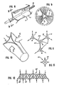
- FIG. 2 there is a desired size relationship between the dimensions of the walls 12 and the optical fibers to be housed therein for abutting engagement. It will be seen from FIG. 2 that the interval between apices 14 of the connector 10 (which in section are the guide longitudinal edges) is preferably approximately twelve times the diameter of the fiber to be housed within the channel 16 defined by the convex walls 12. It is apparent that FIG. 2 is not drawn to scale.
- FIG. 3 illustrates the ability of the rigid wall assembly of FIG. 2 to uniformly collapse about the periphery of optical fibers 1B disposed therein.
- a uniform inward flexing of the walls 12 results in the manner illustrated in FIG. 3. If a force is applied to one apex only and the remaining apices are restrained from spreading apart, the reaction forces at the restrained apices will effect collapse of all of the walls although all of the walls will not collapse uniformly.
- the cross-sectional area of the fiber-receiving channel 16 has been reduced from that of FIG. 2 to that of FIG. 3 in which the peripheries of the optical fibers 18 are tangentially engaged by the innermost portions of each of the convex walls 12.
- a connector made in accordance with this invention is able to assume an initial uncollapsed position illustrated in FIG. 2 whereby the opposed entrance ends may have a sufficiently large cross-sectional area defining the fiber-receiving channel 16 so that the opposed ends of the optical fibers 18 may be readily threaded therein until they abut in the center.
- the walls are collapsed in the manner illustrated in FIG. 3.
- punched ⁇ out recesses 2 0 may be formed at spaced intervals along the length thereof in the manner illustrated in FIG. 1 so as to facilitate inward flexing of each of the walls.
- all walls of a connector are preferably uniformly apertured to assure uniform flexing or collapse, a lesser number may be apertured for particular situations as when employing walls of different thicknesses.
- the connectors made in accordance with this invention may also be uniformly collapsed by the application of a twisting couple to opposed ends thereof in the manner depicted with connector 11 illustrated in FIG. 8.
- the walls 13 thereof are collapsed and twisted along their length in the manner illustrated in FIG. 9.
- either mode of force application resulting in collapse or shrinkage of the cross-sectional area of the fiber-receiving channel of the connectors made in accordance with this invention will work to advantage, that is, either the direct inwardly directed application of force illustrated in FIG. 3 or the application of twisting forces as illustrated in FIG. 8.
- housing 22 has opposed outwardly tapering half portions 24 having longitudinal slots 26 formed therein for allowing radial flexing of the housing. Disposed 120" apart on the inner periphery of the housing 22 are parallel longitudinal grooves 28, each of said grooves being adapted to receive a pair of longitudinal edges of two convex connector walls 30.
- Each of the walls 30 comprises a discrete strip of metal, plastic or the like which is flexible so as to perform the desired optical fiber-aligning function above described.
- the housing walls define an interior, tricuspid, fiber-receiving channel or passageway 32. The illustrated optical fibers 18 may then enter the opposed ends of the passageway 32 defined by the walls 30 until they are in abutting engagement.
- the housing walls defining the passageway 32 are uniformly collapsed inwardly by simultaneously applying collapsing forces.
- the forces are applied to the three connector apices formed by longitudinal edges of the convex walls 30 disposed in housing grooves 28 to which the collapsing forces are in turn imparted by the collapsible housing 22.
- each of the three walls 30 uniformly flexes inwardly until it tangentially engages the peripheral surface portion of the optical fibers 18 within the channel 32.
- the means for effecting such uniform collapsing of the housing 22 includes opposed collapsing sleeves 36.
- Each sleeve has an inner frusto-conical recess 38 adapted to snugly receive and inwardly compress the outer periphery of each tapered housing portion 24 as the sleeve approaches the center of housing 22.
- Disposed on the larger-diameter end of each sleeve 36 are male threads 40 adapted to threadedly engage female threads 42 of coupling ring 44 surrounding the central outer peripheral portion of the housing 22.
- the coupling ring female threads 42 are formed so that such threads may simultaneously engage the male threads of the opposed collapsing sleeves 36.
- the sleeves 36 are threaded home and engage the female threads of the coupling ring 44, they gradually exert uniform collapsing forces on housing 22.
- the forces are transmitted to the apices defined by the longitudinal edges of walls 30, the surfaces of which define fiber-receiving channel 32 in which the opposed ends of fibers 18 are disposed.
- a frusto-conical guide element 43 having an inwardly-converging, funnel-shaped recess 46 is inserted in the interior frusto-conical passageway 38 of each collapsing sleeve 36.
- Such guides not only serve to guide the fibers into end entrances of the tricuspid aligning channel 32 disposed within the collapsible, slotted housing 26, but, in addition, serve to prevent entrance of any dirt or other foreign matter which may affect the efficiency of light transmission between the optical fibers into the housing interior. If a permanent splice between the fiber ends is intended, an appropriate hardenable epoxy resin may be inserted in the recess opening of the conical guide elements 43 to effect a seal and in the channel interior between the fiber ends to assure a permanent connection.
- FIG. 4 Elements of a connector construction 50 for effecting disengageable light transmissive connections between the ends of optical fibers is illustrated in FIG. 4 in disassembled relationship.
- optical fiber cable 52 traverses opening 53 of strain relief nut 54 having female threads 56 which engage male threads 58 of connector housing 60.
- a clamp 62 has jaws 63 thereof disposed in opening 53 about the outer periphery of optical fiber cable 52 from which optical fiber 18 extends, traversing an opening in spacer element 64.
- the clamp may be of the type disclosed in McKee application Serial No. 943,153, filed September 18, 1978 and entitled IMPROVED CLAMP CONSTRUCTION and clamp both the cable 52 and fiber 18.
- central portion C of clamp 62 is of such size as not to pass through opening 53 of nut 54, it functions as a strain relief in conjunction with such nut when an axial pull is imparted to the cable.
- Housing 60 has mounted therein a collapsing element 61 having a flared bore 66 adapted to receive in substantially interfitting relationship the right-hand tapered portion of slotted housing 22M which may be of substantially the same construction as the slotted housing 22 of FIG. 6, with the exception of elongate cylindrical base portion 67 which is partially housed in spacer element 64.
- a "C" ring 69 clamped to base portion 67 prevents axial movement to one left in FIG. 4 by abutting collapsing element 61. Accordingly, the right end of slotted housing 22M is received in the collapsing element frusto-conical bore 66.
- Element 61 has an annular retention flange 70 preventing the element 61 from moving out the open end of cylindrical passageway 72 of the connector housing 60 by engaging inner annular stop shoulder 74.
- Housing 60 is adapted to intermate with connector housing 76 of FIG. 4 having a retained coupling nut 78 with female threads 80 disposed about an inner peripheral distal end portion thereof.
- the coupling nut is retained to the connector body portion 76 by means of an annular shoulder 82 which engages annular stop ring 84 integrally formed with the connector body 76.
- Optical cable 52L enters the connector housing 76 from the left as illustrated in FIG. 4 and trasverses opening 53L of a strain relief nut 54L having male threads 57 which engage housing female threads 59.
- Extending from cable 53L is optical fiber 18L disposed in the connector housing 76.
- Housing 76 has a longitudinal passageway 88 in which is disposed a spring 90 surrounding fiber 18L.
- the spring 90 abuts at the left end against clamp 62L engaging optical fiber cable 52L, and at the opposed right end engages a retractable guide sleeve 94 having a central bore 96 through which optical fiber 18L may pass.
- Fiber portion 18L terminates substantially flush with the end 100 of the housing portion 76 as seen in FIG. 4.
- a housing frusto-conical passageway portion Surrounding the sleeve 94 is a housing frusto-conical passageway portion defining the outer end limit of the connector housing 76.
- the retractable sleeve 94 is stopped in its spring-urged outward movement by means of stop flange 101 defining one end of sleeve 94 upon engaging annular stop shoulder 102 which defines one end limit of cylindrical chamber portion 88 in which flange portion 101 of the retractable sleeve is movable. Accordingly, the spring 90 will move the retractable sleeve outwardly toward the distal end of the frusto-conical passageway 98 of the connector housing 76 until these stop surfaces engage.
- coupling nut 78 is threadedly engaged with male threads 108 disposed on the distal end of the housing 60.
- Such threaded engagement urges distal portion 110 of housing 76 defining frusto-conical recess 98 in which the retractable sleeve is reciprocally movable, into telescoping engagement with the end portion of the cylindrical bore 72 of the housing 60.
- the frusto-conically relieved body portion 110 of the housing 76 will simultaneously have the inner peripheral surface 98 thereof slidably engaged with and collapse the left frusto-conical surface portion of the collapsible slotted housing 22M as appearing in FIG. 4 which is disposed within the housing 60_.
- the distal end of retractable sleeve 94 abuts against the distal end of housing 68 during threaded engagement of the connector housings and is thus forced to gradually retract into the position of FIG. 5. It will be noted from FIGS.
- the distal end of fiber passageway 96 through which fiber 18L passes is relieved at 97 to eliminate any sharp edges which might scrape or otherwise impair the outer cladding disposed about the periphery of fiber 18L.
- the guide sleeve 94 retracts, the optical fiber 18L continues to pass into the interior of the optical fiber-receiving passageway 32 defined by the walls 30 disposed within the interior of the slotted housing 22M as seen in Fig. 7. Accordingly, two functions are carried out simultaneously.
- the slotted housing 22M is radially collapsed so as to shrink the cross section of the fiber-receiving passageway 32, thereby aligning the ends of the fibers 18 and 18L, as simultaneously the fiber 18L progresses into the passageway.
- the optical fibers are in desired abutting relationship as well as in desired coaxial relationship for purposes of effecting a desired light transmissive connection. This condition is illustrated in FIG. 5 of the drawing.
- FIG. 7 is a transverse sectional view illustrating the manner in which the curved, discrete guide panels or walls 30 are received within the horizontal parallel grooves 28 which are formed 120° apart on the inner periphery of the slotted, resiliently collapsible housing 22M. It will be noted from FIG. 7 that the grooves 28 are positioned between the housing slots 26 formed in the housing 22M. The latter slots enable the various segments of the collapsible housing to flex inwardly for purposes of uniformly urging the apices of the triangularly-shaped channel 32 defined by the longitudinal edges of the discrete curved walls 30, inwardly so as to effect a simultaneous inward flexing of the curved surface portions of each of the walls or walls 30.
- the connector 50 of FIGS. 4 and 5 is adapted for use in the field by a workman who need not be technically skilled.
- the connector 50 is adapted for repeated fiber connect-disconnect operations in the course of effecting light transmissive connections between optical fiber ends.
- a desired index-matching gel or liquid may be disposed in the interior of the channel 32 defined by the walls 30 in the vicinity of the juncture between the two fiber ends so as to enhance any light transmission and minimize light loss.
- the terminal ends of the illustrated fibers 18 and 18L of FIG. 4 engage in abutting relationship with no interval therebetween.
- the lengths of the fibers 18 and 18L disposed within the connector assembly of FIGS. 4 and 5 be slightly greater than the interval between the ends of the optical fiber cables 52 and 52L from which the optical fibers extend.
- a slight bow or strain relief in the fiber may be present as at 124 in FIG. 5 between the terminal end of the retractable sleeve 94 and the clamp 62L.
- FIGS. 4 and 5 as well as that of FIG. 6 employ screw-type engagements between the engageable halves
- equivalent constructions may employ a bayonet, snap- type fit between the joining halves in which the collapsible triangular channel-forming element is disposed, and the resulting construction will work to equal advantage with those previously described.
- the connector of this application by virtue of its rigidity of structure is able to collapse in a plurality of manners providing for flexibility in the normal course of installation and use.
- the collapsing force imparted to the tricuspid channel may be imparted to one apex and, assuming the other two apices may react to such force, the latter will result in collapse of the fiber-receiving interior passageway defined by the collapsed walls.
- the provided connector may be construed as a three-point spring element acting in a radial direction through each apex and resisting crush forces.
- FIG. 10 is a perspective view illustrating the manner whereby a tricuspid channel made in accordance with this invention may be formed from an integral cylindrical tubing by the application of collapsing forces disposed 120 0 apart so as to form the desired triangular sectional configuration, as illustrated in the upper portion of the collapsed tube 15. Following formation of the triangular cross-section the concave walls should be resiliently flexible to provide the fiber-aligning functions above described.
- FIG. 11 is illustrative of contiguous generally triangular optical fiber guide elements 11C which may be integrally formed from unitary sheet members 30C whereupon the application of collapsing forces in the direction of the arrows normal to the apices defined by the sheets 30C will result in simultaneous uniform collapse of the fiber-receiving channels 16. It is thus apparent that the structure of the fiber guide illustrated in FIGS. 1 through 3 may be multiplied upon itself into the configuration of FIG. 11 or one similar thereto.
- FIG. 12 illustrates a further modified guide 10F wherein the individual interconnected triangular guide elements 11F are simultaneously collapsed by the application of opposed forces indicated by the arrows.
- the collapsible guide 10F of FIG. 12 would find application for use in conjunction with a plurality of optical fibers in the form of a flat cable or the like in which parallel discrete fibers are to be simultaneously connected in substantially the same horizontal plane.
- one series of apices in Fig. 12 is stationary and forces are applied to the opposed, substantially linearly aligned series of tapered wall edges.
- FIG. 13 is illustrative of a modified collapsible guide 116 and depicts the ability of this invention to be incorporated in a collapsing guide structure composed of more than three wall portions.
- inwardly convex walls 118 illustrated in FIG. 13 may be discrete and maintained in a slotted collapsible housing, welded together, or formed from an integral tube or an integral sheet joined along terminal longitudinal edges.
- Guide l16 is illustrative of the ability of the invention of this application to be incorporated in any sectional configuration in which the number of collapsing walls may be a number greater than three.
- the connectors of this invention also provide for uniform or substantally uniform shrinkage of the fiber-receiving passageway so that the fiber ends disposed within such passageway may be aligner along a longitudinal axis.
- the connector channel collapsing force is readily applied to one or more tapered edges of converging walls defining such channel.
- the basic connector construction comprising collapsing walls disclosed in this application may be incorporated in a variety of fiber connector constructions.
- the material of fabrication of the guide of this invention may be plastic or a metal such as a phosphorus-bronze alloy or copper. Such materials of fabrication are presented by way of example only as it is apparent to those skilled in the art that any material of fabrication will work to advantage if it possesses the property of being able to uniformly or substantially uniformly flex and collapse in the manner above described.
- stop means may be provided to prevent the application of crushing forces on the fibers by the innermost portions of the wall surfaces which could result in fiber damage and light loss.
- thin, apertured Mylar or other plastic coverings may be disposed over opposed ends of the connector fiber-receiving channels to prevent dirt contamination of the fiber juncture.
Landscapes
- Physics & Mathematics (AREA)
- General Physics & Mathematics (AREA)
- Optics & Photonics (AREA)
- Mechanical Coupling Of Light Guides (AREA)
Applications Claiming Priority (2)
| Application Number | Priority Date | Filing Date | Title |
|---|---|---|---|
| US149889 | 1980-05-14 | ||
| US06/149,889 US4353620A (en) | 1980-05-14 | 1980-05-14 | Optical fiber connector construction |
Publications (1)
| Publication Number | Publication Date |
|---|---|
| EP0039954A1 true EP0039954A1 (en) | 1981-11-18 |
Family
ID=22532226
Family Applications (1)
| Application Number | Title | Priority Date | Filing Date |
|---|---|---|---|
| EP81103677A Withdrawn EP0039954A1 (en) | 1980-05-14 | 1981-05-13 | Optical fiber connector construction |
Country Status (4)
| Country | Link |
|---|---|
| US (1) | US4353620A (enExample) |
| EP (1) | EP0039954A1 (enExample) |
| JP (1) | JPS57501251A (enExample) |
| WO (1) | WO1981003384A1 (enExample) |
Cited By (3)
| Publication number | Priority date | Publication date | Assignee | Title |
|---|---|---|---|---|
| EP0124703A1 (de) * | 1983-03-11 | 1984-11-14 | INOVAN GmbH & Co. KG Metalle und Bauelemente | Steckverbinder für Lichtwellenleiter |
| GB2147430A (en) * | 1983-10-03 | 1985-05-09 | Conax Corp | Collet-chyck type optical fiber terminator |
| WO1987003102A1 (en) * | 1985-11-08 | 1987-05-21 | American Telephone & Telegraph Company | Optical fiber connector and method for using same |
Families Citing this family (26)
| Publication number | Priority date | Publication date | Assignee | Title |
|---|---|---|---|---|
| US4383736A (en) * | 1980-11-24 | 1983-05-17 | The United States Of America As Represented By The Secretary Of The Navy | Pressure formed fiber optic connector |
| CA1158900A (en) | 1981-01-14 | 1983-12-20 | Lucas Soes | Connector for use in butt splicing two optical fibres |
| US4458984A (en) * | 1981-09-21 | 1984-07-10 | Augat Inc. | Assembly for thermally actuated optic fiber jointing device |
| US4545644A (en) * | 1983-10-04 | 1985-10-08 | At&T Bell Laboratories | Optical fiber connector and articles connected therewith |
| US4699454A (en) * | 1984-03-29 | 1987-10-13 | American Telephone And Telegraph Company, At&T Bell Laboratories | Fiber optic connector |
| US4725120A (en) * | 1984-10-25 | 1988-02-16 | American Telephone And Telegraph Company, At&T Bell Laboratories | Connector apparatus |
| US4738507A (en) * | 1985-05-31 | 1988-04-19 | American Telephone And Telegraph Company, At&T Technologies, Inc. | Optical fiber connectors and methods of making |
| US4738508A (en) * | 1985-06-28 | 1988-04-19 | American Telephone And Telegraph Company, At&T Technologies, Inc. | Terminated optical fiber and methods of making |
| US4793683A (en) * | 1986-05-08 | 1988-12-27 | American Telephone And Telegraph Company, At&T Bell Laboratories | Optical fiber connector |
| US4863235A (en) * | 1986-07-21 | 1989-09-05 | American Telephone And Telegraph Company, At&T Bell Laboratories | Connector for optical fiber cable |
| US5000536A (en) * | 1986-07-21 | 1991-03-19 | At&T Bell Laboratories | Connector for optical fiber cable |
| US5013123A (en) * | 1988-04-18 | 1991-05-07 | Minnesota Mining And Manufacturing Company | Stamped precision lightguide interconnect centering element |
| US4865412A (en) * | 1988-04-18 | 1989-09-12 | Minnesota Mining And Manufacturing Company | Connector for splicing optical fiber cables |
| US4818055A (en) * | 1988-04-18 | 1989-04-04 | Minnesota Mining And Manufacturing Company | Optical fiber splice connector |
| US4824197A (en) * | 1988-04-18 | 1989-04-25 | Minnesota Mining And Manufacturing Company | Stamped precision lightguide interconnect centering element |
| US5102212A (en) * | 1988-04-18 | 1992-04-07 | Minnesota Mining And Manufacturing Company | Stamped precision lightguide interconnect centering element |
| US4915472A (en) * | 1988-12-28 | 1990-04-10 | American Telephone And Telegraph Company, At&T Bell Laboratories | Optical fiber terminal plug connectors |
| US5155787A (en) * | 1991-09-06 | 1992-10-13 | Minnesota Mining And Manufacturing Company | Multiple optical fiber splice element having ramped porch |
| US5155781A (en) * | 1991-09-06 | 1992-10-13 | Minnesota Mining And Manufacturing Company | Multiple optical fiber splice with sealing end covers |
| US5151964A (en) * | 1991-09-06 | 1992-09-29 | Minnesota Mining And Manufacturing Company | Wedge-actuated multiple optical fiber splice |
| US5920669A (en) * | 1997-06-06 | 1999-07-06 | Siecor Corporation | Receptacle having a rotatable coupling nut for engaging a fiber optic connector assembly |
| JP3710083B2 (ja) * | 1999-03-17 | 2005-10-26 | 日本板硝子株式会社 | 光ファイバ接続用ガラス部品の製造方法 |
| US6810196B2 (en) * | 2002-08-30 | 2004-10-26 | Fitel Usa Corp. | Variable attenuator for optical fiber applications |
| US6807358B2 (en) * | 2002-08-30 | 2004-10-19 | Fitel Usa Corp. | Variable attenuator for optical fiber applications and method of making |
| US7509000B2 (en) * | 2006-03-20 | 2009-03-24 | Baker Hughes Incorporated | Downhole optic fiber wet connect system and method |
| US7712973B2 (en) * | 2008-09-04 | 2010-05-11 | Fibersource, Inc. | Fiber optic connector |
Citations (2)
| Publication number | Priority date | Publication date | Assignee | Title |
|---|---|---|---|---|
| DE2603885A1 (de) * | 1975-02-03 | 1976-08-05 | Northern Electric Co | Verbindungsstueck fuer optische fasern |
| EP0026139A1 (fr) * | 1979-09-21 | 1981-04-01 | Socapex | Embout de connexion pour fibre optique et procédé de centrage d'une fibre optique dans un tel embout |
Family Cites Families (20)
| Publication number | Priority date | Publication date | Assignee | Title |
|---|---|---|---|---|
| AT325326B (de) * | 1972-07-10 | 1975-10-10 | Siemens Ag | Verbindungsstecker für optische glasfasern und verfahren zur herstellung fester verbindungen unter verwendung eines verbindungssteckers |
| DE2340019A1 (de) * | 1973-08-07 | 1975-02-20 | Siemens Ag | Kopplung fuer lichtleitfasern untereinander und fuer lichtleitfasern mit endgeraeten |
| GB1433755A (en) * | 1973-09-01 | 1976-04-28 | Plessey Co Ltd | In-line coupling of two lengths of linear optical waveguide elements |
| GB1448742A (en) * | 1973-09-25 | 1976-09-08 | Post Office | Optical communications systems |
| GB1456395A (en) * | 1973-11-16 | 1976-11-24 | Bicc Ltd | Optical fibre connector |
| US3950075A (en) * | 1974-02-06 | 1976-04-13 | Corning Glass Works | Light source for optical waveguide bundle |
| JPS50136045A (enExample) * | 1974-04-15 | 1975-10-28 | ||
| DK143620A (enExample) * | 1974-06-20 | |||
| US3885859A (en) * | 1974-06-24 | 1975-05-27 | Northern Electric Co | Optical fibre connectors |
| US3871744A (en) * | 1974-08-19 | 1975-03-18 | Gte Laboratories Inc | Optical fiber connector |
| US3947182A (en) * | 1974-10-29 | 1976-03-30 | International Telephone & Telegraph Corporation | Fiber optic connector with axial tolerance relief |
| US3936145A (en) * | 1974-11-07 | 1976-02-03 | International Telephone And Telegraph Corporation | Fiber optic alignment sleeve |
| FR2291510A1 (fr) | 1974-11-13 | 1976-06-11 | Cit Alcatel | Connecteur pour fibres optiques |
| US4008948A (en) * | 1975-06-30 | 1977-02-22 | Northern Telecom Limited | Optical fibre connectors |
| US3990779A (en) * | 1975-07-24 | 1976-11-09 | International Telephone And Telegraph Corporation | Single optical fiber connector |
| US4047796A (en) * | 1975-09-15 | 1977-09-13 | International Telephone And Telegraph Corporation | Precision optical fiber connector |
| US4088390A (en) * | 1975-11-05 | 1978-05-09 | International Telephone And Telegraph Corporation | Single optical fiber connector |
| US4193665A (en) * | 1976-03-01 | 1980-03-18 | International Telephone And Telegraph Corporation | Fiber optic contact alignment device |
| US4047797A (en) * | 1976-06-09 | 1977-09-13 | International Telephone And Telegraph Corporation | Fiber optic connector |
| GB1556476A (en) | 1976-10-07 | 1979-11-28 | Standard Telephones Cables Ltd | Fibre connector |
-
1980
- 1980-05-14 US US06/149,889 patent/US4353620A/en not_active Expired - Lifetime
-
1981
- 1981-05-13 JP JP56502039A patent/JPS57501251A/ja active Pending
- 1981-05-13 WO PCT/US1981/000634 patent/WO1981003384A1/en not_active Ceased
- 1981-05-13 EP EP81103677A patent/EP0039954A1/en not_active Withdrawn
Patent Citations (4)
| Publication number | Priority date | Publication date | Assignee | Title |
|---|---|---|---|---|
| DE2603885A1 (de) * | 1975-02-03 | 1976-08-05 | Northern Electric Co | Verbindungsstueck fuer optische fasern |
| FR2299655A1 (fr) * | 1975-02-03 | 1976-08-27 | Northern Electric Co | Connecteur pour fibres optiques |
| GB1467750A (en) * | 1975-02-03 | 1977-03-23 | Northern Electric Co | Connectors for optical fibres |
| EP0026139A1 (fr) * | 1979-09-21 | 1981-04-01 | Socapex | Embout de connexion pour fibre optique et procédé de centrage d'une fibre optique dans un tel embout |
Non-Patent Citations (1)
| Title |
|---|
| Machine Design, Vol. 52, No. 1, January 1980, Ohio, US "Scanning the Field of Ideas", page: circle 131. * entirely * * |
Cited By (3)
| Publication number | Priority date | Publication date | Assignee | Title |
|---|---|---|---|---|
| EP0124703A1 (de) * | 1983-03-11 | 1984-11-14 | INOVAN GmbH & Co. KG Metalle und Bauelemente | Steckverbinder für Lichtwellenleiter |
| GB2147430A (en) * | 1983-10-03 | 1985-05-09 | Conax Corp | Collet-chyck type optical fiber terminator |
| WO1987003102A1 (en) * | 1985-11-08 | 1987-05-21 | American Telephone & Telegraph Company | Optical fiber connector and method for using same |
Also Published As
| Publication number | Publication date |
|---|---|
| JPS57501251A (enExample) | 1982-07-15 |
| WO1981003384A1 (en) | 1981-11-26 |
| US4353620A (en) | 1982-10-12 |
Similar Documents
| Publication | Publication Date | Title |
|---|---|---|
| US4353620A (en) | Optical fiber connector construction | |
| US4225214A (en) | Connector construction | |
| US4435038A (en) | Connector for use in butt splicing two optical fibres | |
| US4056305A (en) | Single optical fiber connector utilizing elastomeric alignment device | |
| US4279466A (en) | Hermaphroditic fiber optic connector | |
| CA1040467A (en) | Fiber optic connector with axial tolerance relief | |
| US3963323A (en) | Fiber optic connector with protective cable sleeves | |
| US4201444A (en) | Single optical fiber connector | |
| US4140367A (en) | Multiple channel connector for fiber optic cables | |
| US5971626A (en) | Fiber optic connector and connector sleeve assembly | |
| US4183619A (en) | Connector pin assembly and method for terminating an optical fiber | |
| US4258977A (en) | Optical fibre connector | |
| CA1095759A (en) | Hermaphrodite optical fiber connector | |
| DE69802496T2 (de) | Verbinder für optische Fasern aus Kunststoff | |
| US4208092A (en) | Fiber optic multi-cable pair connector | |
| US4008948A (en) | Optical fibre connectors | |
| US4339171A (en) | Fiber optic cable retainer member | |
| US4192575A (en) | Guide-connector assembly for joining optical fibers and method of making guide therefor | |
| US4824198A (en) | Housing for a fiber optic splice | |
| JPH0215844B2 (enExample) | ||
| US4730891A (en) | Multiple-channel optical fiber connector assembly | |
| US4021098A (en) | Fiber bundle consolidation | |
| US4448482A (en) | Variable geometry optical fiber connector | |
| GB1602587A (en) | Connector for sumultaneous end-to-end connection of groups of seven optical fibres | |
| US4088390A (en) | Single optical fiber connector |
Legal Events
| Date | Code | Title | Description |
|---|---|---|---|
| PUAI | Public reference made under article 153(3) epc to a published international application that has entered the european phase |
Free format text: ORIGINAL CODE: 0009012 |
|
| AK | Designated contracting states |
Designated state(s): DE FR GB IT |
|
| 17P | Request for examination filed |
Effective date: 19820508 |
|
| RAP1 | Party data changed (applicant data changed or rights of an application transferred) |
Owner name: TRW INC |
|
| STAA | Information on the status of an ep patent application or granted ep patent |
Free format text: STATUS: THE APPLICATION IS DEEMED TO BE WITHDRAWN |
|
| 18D | Application deemed to be withdrawn |
Effective date: 19850416 |
|
| RIN1 | Information on inventor provided before grant (corrected) |
Inventor name: SCHULTZ, RONALD L. |