EP0039610B1 - Laufrollen - Google Patents
Laufrollen Download PDFInfo
- Publication number
- EP0039610B1 EP0039610B1 EP81301967A EP81301967A EP0039610B1 EP 0039610 B1 EP0039610 B1 EP 0039610B1 EP 81301967 A EP81301967 A EP 81301967A EP 81301967 A EP81301967 A EP 81301967A EP 0039610 B1 EP0039610 B1 EP 0039610B1
- Authority
- EP
- European Patent Office
- Prior art keywords
- castor
- halves
- fork
- bearing balls
- track
- Prior art date
- Legal status (The legal status is an assumption and is not a legal conclusion. Google has not performed a legal analysis and makes no representation as to the accuracy of the status listed.)
- Expired
Links
- 235000004443 Ricinus communis Nutrition 0.000 title claims abstract description 52
- 240000000528 Ricinus communis Species 0.000 title description 3
- 238000005096 rolling process Methods 0.000 claims description 7
- 230000000295 complement effect Effects 0.000 claims description 6
- 230000013011 mating Effects 0.000 claims description 6
- 229920003023 plastic Polymers 0.000 abstract description 10
- 239000004033 plastic Substances 0.000 abstract description 10
- 239000002184 metal Substances 0.000 description 6
- 239000000463 material Substances 0.000 description 5
- 238000007789 sealing Methods 0.000 description 5
- 238000010276 construction Methods 0.000 description 4
- 230000001419 dependent effect Effects 0.000 description 3
- 238000009434 installation Methods 0.000 description 2
- 229930182556 Polyacetal Natural products 0.000 description 1
- 239000013536 elastomeric material Substances 0.000 description 1
- 229920002457 flexible plastic Polymers 0.000 description 1
- 229920006122 polyamide resin Polymers 0.000 description 1
- 229920006324 polyoxymethylene Polymers 0.000 description 1
Images


Classifications
-
- B—PERFORMING OPERATIONS; TRANSPORTING
- B60—VEHICLES IN GENERAL
- B60B—VEHICLE WHEELS; CASTORS; AXLES FOR WHEELS OR CASTORS; INCREASING WHEEL ADHESION
- B60B33/00—Castors in general; Anti-clogging castors
- B60B33/0028—Construction of wheels; methods of assembling on axle
Definitions
- This invention relates to a swivelling castor comprising a fork between the dependent legs of which a wheel or other roller is mounted about an axis which is horizontally disposed in use.
- the fork is mounted for castoring or swivelling movement about an axis vertically disposed in use and spaced from the horizontal rolling axis.
- the vertical axis is usually comprised by a stem or other element attachable to the article to be supported by the castor.
- a swivelling wheeled castor comprising two similar fork halves each of said fork halves comprising a leg said fork halves having means for detachable interengagementwith one another according to GB-A-1150617, said castor being characterised in that together said fork halves provide part of a circular horizontal track for bearing balls at the upper part of the castor from which the fork legs depend, these bearings supporting a mounting stem for relative swivelling movement about a vertical castoring axis B; and part of a circular vertical track for bearing balls on a circumference around the rolling axis A an outer wheel being mounted for the rolling movement on said bearing balls.
- the castor illustrated therein comprises a wheel 1 mounted for rolling movement about an axis A between the dependent legs 2 and 3 of castor fork halves 4 and 5.
- the top part of the castor comprises a snap-on cap 6 and a metal mounting stem 7 on castoring axis B in position within the cap.
- the stem and castor as will be explained, are mounted for relative swivelling or castoring about axis B.
- the stem 7 has a lower part 40 which carries the inner bearing components and has an upwardly extending reduced threaded portion 41.
- Each castor fork half 4 and 5 comprises an upper vertically disposed part 8 and a rearwardly inclined part 9 supporting wheel 1.
- the upper part 8 has an inwardly extending rim 10, the top corner of which is chamfered away to define the bottom outer sector 11 of a trackfor bearing balls.
- a lower ball race 12 located on the lower part 40 of stem 7 has a complementary bottom inner sector 13.
- An upper ball race 14 also located on the lower part 40 of stem 7 also has a complementary top inner sector 15 and the bearing assembly is completed by the snap-on cap 6 also with a top outer sector 16.
- the upper surface of ball race 14, when assembled, is positioned flush with the shoulder defined by the upper annular surface of stem part 40 and sealing lips 42 extend to the upper surface of cap 6.
- the track for bearing balls 23 is defined by inner sectors 13 and 15 of ball races 12 and 14 respectively and outer sectors 11a, 11b and 16 of the castor halves 4 and 5 and the cap respectively. More usually in a castor the balls run between upper and lower tracks.
- each leg 2 and 3 has a shallow annular projection or pip 17 and above pip 17 a shallow recess 18. Above recess 18 upper part 8 extends upwardly as an undercut lip 19. Pip 17, recess 18 and lip 19 all constitute mating parts respectively with a complementary annular recess 20, annular pip 21 and annular channel 22 that are each formed in cap 6.
- the castor halves 4 and 5 and cap 6 are formed in a relatively hard resiliently flexible plastics material so that the cap 6 snaps tightly and securely over the castor halves 4 and 5 to complete the castor.
- the plastics material and that from which ball races 12 and 14 are formed, is moreover chosen for its suitability to provide a track for bearing balls 23. Suitable materials include a polyacetal copolymer and the polyamide resins.
- each leg 2, 3 is formed inwardly into a hub or boss 24 ( Figure 4) having an annular flange 25.
- Flanges 25 on legs 2, 3 have complementary mating parts and together with the wheel 2 proper provide a track for wheel bearings.
- each flange 25 has an array of six complementary mating members three male members 26 and three female members 27, the members in one leg being offset with relation to those in the other so to achieve mating.
- the specific form of these mating members can well be seen in Figure 4.
- Each male member 26 comprises a right cylindrical spigot with an enlarged outer end 28.
- Each female member 27 is a right cylindrical socket to receive the right cylindrical spigot, the ends of the socket being chamfered at 29 to allow entry and locking exit of male member 28.
- a snap engaged plug 30 covers each countersink 24.
- each flange 25 are recessed at 31 to define the inner part of a track for wheel bearing balls 32.
- the wheel 1 is made of two axially separable halves 33 and 34 joined by the resilient inter-engagement of male members 35 and female members 36, the male members 35 again having end enlargements 37 to achieve interlock.
- the wheel halves are recessed at 38 to define the upper part of a track for balls 32.
- the wheel halves adjacent recesses 38 have sealing lips 43 which abut flanges 25 carried by legs 2 and 3.
- a tyre 39 of elastomeric material is trapped between wheel halves 33 and 34. This is an advantageous feature allowing ready installation of the tyre.
- the wheel construction which is believed to be novel in itself offers advantage in that the bearing has a large radius, i.e. the countersinks 24 and associated parts are a hub of substantial radius which allows a low point loading on the relatively large balls used. This low loading means minimal track wear.
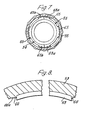
- the second exemplary castor illustrated comprises a wheel 50 mounted for rolling movement about a horizontal axis AA between the dependent legs 51 and 52 of castor fork halves 53 and 54 again formed of a hard plastics material.
- the top part of the castor comprises a fitted plastics cap 55 and a metal mounting stem 71 the stem and the castor being able to be swivelled about a castoring axis B.
- each castor half 53, 54 has an inwardly extending rim 56 the upper inner corner of which is chamfered to define the bottom outer sector 57 of a track for bearing balls 70.
- a lower plastics ball race member 58 surrounds and houses a short vertically extending metal bush 59 surrounding mounting stem 71. The upper edges of race member 58 is chamfered to define the bottom inner sector 60 of the ball bearing track.
- a sealing lip 61 on member 58 extends downwardly and outwardly to about the inside of the castor legs.
- a locating recess 62 is formed in the upper surface of the lower ball race member 58 around the bush 59.
- the cap 55 has a part-circular inwardly and downwardly directed sectorial recess 64 forming the upper sector of the outer part on the ball bearing track.
- the cap 55 has inwardly extending projections 65 for engaging under the projection 63 on the castor fork halves 53 and 54, the arrangement being that the leg and cap have a bayonet-type connection wherein at a first relative angular position of the cap and registering castor fork halves the projections 63 and 65 are not coincident and can be engaged with one another in the desired abutting orientation of the associated parts.
- the projections 65 thereon engage under the projections 63 to secure the cap and castor halves in the position illustrated.
- a single projection 65 on the cap engages under and bridges two projections 63a and 63b on the castor fork halves.
- Stops 66 are provided on the cap to locate the projections in register. The stops are illustrated on an enlarged scale in Figure 8.
- One of the stops 66, the entry stop has an inclined ramp 66a to allow projection 65 to ride over it into the engaged position between the stops.
- only two sets of projections are provided each bridging a slit between the castor fork halves and extending for an arc that subtends just under one right angle.
- the ball race is completed by an upper plastics race member 67 fitting over the cap 55 and located for assembly purposes by an annular rib 68 engaging recess 62 on lower washer 58.
- the race member 67 has a downwardly and outwardly facing part-circular sectorial recess 69 providing the upper part of the inner bearing track.
- Bearing balls 70 are located in the track defined by inner sectors 60 and 69 and outer sectors 57 and 64. It should be noted again that the bearing track is defined between inner and outer pairs of sectors as opposed to upper and lower parts.
- the threaded stem 71 has a hexagonal head 72 and extends upwardly through the bush 59. Atop flat metal washer 73 seats in an upper recess 74 in plastics washer 67. A sealing lip 75 on plastics upper ball race member 67 together with lip 61 on lower ball race member 58 prevents ingress of dirt to the bearing.
- each castor leg 51, 52 is provided with an inwardly extending cylindrical boss, a male boss 76 ad a female boss 77.
- the male boss has an inwardly extending concentric spigot 78 of a bayonet connection having three radially outwardly extending generally rectangular projections 79.
- the female boss 77 with a socket 80 to receive spigot 78 has three recesses 81 corresponding to projections 79 so that when the projections and recesses 81 register the two bosses 76 and 77 can be pressed together to the desired relationship. In this orientation the upper parts of the castor are not in register.
- the wheel 50 has a corresponding track 83 with interposed bearing balls 84 and a tyre 85 that is an interference fit onto the wheel.
- the wheel construction with the large radius bearing (the bosses 76 and 77 being the large diameter hub) offers the same running advantages as pointed out in the first embodiment described with reference to Figures 1 to 4.
- the outer part of the wheel of Figures 5 to 7, however, is of a unitary construction.
- end caps 86 having inwardly directed sockets 87.
- a dog-bone shaped member 88 with enlarged heads 89 is a snap connection with the sockets to hold the caps 86 in position.
Landscapes
- Engineering & Computer Science (AREA)
- Mechanical Engineering (AREA)
- Pivots And Pivotal Connections (AREA)
- Medicines Containing Material From Animals Or Micro-Organisms (AREA)
- Braking Arrangements (AREA)
Claims (5)
Priority Applications (1)
| Application Number | Priority Date | Filing Date | Title |
|---|---|---|---|
| AT81301967T ATE15467T1 (de) | 1980-05-06 | 1981-05-05 | Laufrollen. |
Applications Claiming Priority (2)
| Application Number | Priority Date | Filing Date | Title |
|---|---|---|---|
| GB8014993 | 1980-05-06 | ||
| GB8014993 | 1980-05-06 |
Publications (3)
| Publication Number | Publication Date |
|---|---|
| EP0039610A2 EP0039610A2 (de) | 1981-11-11 |
| EP0039610A3 EP0039610A3 (en) | 1982-07-14 |
| EP0039610B1 true EP0039610B1 (de) | 1985-09-11 |
Family
ID=10513240
Family Applications (1)
| Application Number | Title | Priority Date | Filing Date |
|---|---|---|---|
| EP81301967A Expired EP0039610B1 (de) | 1980-05-06 | 1981-05-05 | Laufrollen |
Country Status (4)
| Country | Link |
|---|---|
| US (1) | US4404707A (de) |
| EP (1) | EP0039610B1 (de) |
| AT (1) | ATE15467T1 (de) |
| DE (1) | DE3172206D1 (de) |
Families Citing this family (16)
| Publication number | Priority date | Publication date | Assignee | Title |
|---|---|---|---|---|
| DE3148916C2 (de) * | 1981-12-10 | 1984-03-29 | Paul Vom Stein & Co, 5632 Wermelskirchen | Laufrolle für insbesondere Apparate, Transportgeräte od. dgl. |
| GB8403186D0 (en) * | 1984-02-08 | 1984-03-14 | Wilkins P S | Caster assembly |
| GB8422660D0 (en) * | 1984-09-07 | 1984-10-10 | Colson Castors Europ Ltd | Twinwhell castor |
| BE1006258A6 (fr) * | 1992-10-26 | 1994-07-05 | Icd Holding | Ensemble comprenant une roue et un organe de suspension. |
| US5528794A (en) * | 1994-09-09 | 1996-06-25 | Emerson Electric Co. | Utility vacuum cleaner tool caddy and wheel mount |
| US5568671A (en) * | 1994-12-01 | 1996-10-29 | Fki, Industries, Inc. | Caster assembly with integral plastic stem and horn and with removable axle lock cap |
| US6336685B1 (en) | 1999-10-26 | 2002-01-08 | Kenneth R. Orr | Embedded single bearing wheel |
| US6568031B1 (en) * | 2000-03-03 | 2003-05-27 | Finger Lakes Intellectual Property, Llc | Caster assembly for a bed frame member or furniture |
| US6494544B1 (en) | 2000-09-07 | 2002-12-17 | Shop Vac Corporation | Axle and wheel mounting system for a wet/dry vacuum cleaner |
| US6839939B2 (en) * | 2001-06-04 | 2005-01-11 | William J Donakowski | Hubless caster |
| US20110186398A1 (en) * | 2010-01-29 | 2011-08-04 | Heys (USA), Inc. | Hard-Sided Expandable Suitcase |
| US9604500B2 (en) | 2014-03-10 | 2017-03-28 | Kevin Alan Tussy | Low profile caster |
| EP3149549A4 (de) * | 2014-05-27 | 2018-01-10 | Bluesmart Inc. | Aktiver behälter |
| USD795045S1 (en) | 2015-04-30 | 2017-08-22 | Bluesmart Inc. | Container wheel |
| US12030341B2 (en) | 2017-11-27 | 2024-07-09 | Omco Sumo, Inc. | Caster braking system technology |
| US11498360B2 (en) | 2019-05-21 | 2022-11-15 | Ngs Capital Management, Llc | Hybrid bearing arrangement caster technology |
Family Cites Families (13)
| Publication number | Priority date | Publication date | Assignee | Title |
|---|---|---|---|---|
| US2184038A (en) * | 1937-11-03 | 1939-12-19 | Atwood Vacuum Machine Co | Swivel caster |
| GB1150617A (en) * | 1967-02-27 | 1969-04-30 | Flexello Castors & Wheels Ltd | Improvements in Castors |
| US3537125A (en) * | 1967-10-25 | 1970-11-03 | Us Caster Corp | Caster with integral horn and pintle and method of making same |
| DE2019867C3 (de) * | 1970-04-24 | 1975-11-13 | Tente-Rollen Gmbh & Co, 5678 Wermelskirchen | Laufrolle |
| US3718942A (en) * | 1970-08-14 | 1973-03-06 | H Arenson | Caster assembly with integral horn and pintle and method of making same |
| GB1382272A (en) * | 1972-01-07 | 1975-01-29 | Guy Raymond Eng Co Ltd | Furniture legs |
| GB1366583A (en) * | 1972-07-11 | 1974-09-11 | Flexello Castors Wheels Ltd | Castors |
| US4043603A (en) * | 1975-06-16 | 1977-08-23 | Amt Corporation | Vehicle wheel assembly for a toy vehicle |
| US4054339A (en) * | 1975-09-29 | 1977-10-18 | Federal-Mogul Corporation | High impact bearing and method of making same |
| US4097954A (en) * | 1977-01-26 | 1978-07-04 | Roll-Rite Corp. | Flutter-resistant caster |
| US4122580A (en) * | 1977-06-15 | 1978-10-31 | Pemco-Kalamazoo, Inc. | Solid axle wheel support and sealed bearing construction |
| US4170384A (en) * | 1977-09-29 | 1979-10-09 | American Wheel & Engineering Co., Inc. | Molded wheel having a decorative sidewall |
| US4318204A (en) * | 1980-05-02 | 1982-03-09 | Pemco-Kalamazoo, Inc. | Disk wheel with bearing housing injection molded therein |
-
1981
- 1981-05-05 EP EP81301967A patent/EP0039610B1/de not_active Expired
- 1981-05-05 DE DE8181301967T patent/DE3172206D1/de not_active Expired
- 1981-05-05 AT AT81301967T patent/ATE15467T1/de not_active IP Right Cessation
- 1981-05-20 US US06/266,589 patent/US4404707A/en not_active Expired - Fee Related
Also Published As
| Publication number | Publication date |
|---|---|
| DE3172206D1 (en) | 1985-10-17 |
| US4404707A (en) | 1983-09-20 |
| EP0039610A2 (de) | 1981-11-11 |
| EP0039610A3 (en) | 1982-07-14 |
| ATE15467T1 (de) | 1985-09-15 |
Similar Documents
| Publication | Publication Date | Title |
|---|---|---|
| EP0039610B1 (de) | Laufrollen | |
| US2779965A (en) | Ball caster | |
| CA1169648A (en) | Tilt and rotate apparatus for a display monitor | |
| US4346921A (en) | Drainage inspection chambers | |
| EP0154546A2 (de) | Laufrolle | |
| CA1191116A (en) | Wheeled suitcase | |
| US4706329A (en) | Twin-wheel castor | |
| EP0268145B1 (de) | Lenkrolle | |
| CA2110109A1 (en) | Caster with a fouling-resistant bearing cup feature and method of manufacturing the same | |
| US3048447A (en) | Toy white side wall tire | |
| CA1118019A (en) | A-361 wheel and hub cap assembly | |
| US3387252A (en) | Waterproof cover assembly for electric sockets | |
| US4348784A (en) | Swivel type caster with seal and lubrication ring | |
| US4653139A (en) | Caster with a plain thrust bearing between the wheel frame and the frame carrier | |
| CA1144720A (en) | Disk wheel with bearing housing injection molded therein | |
| US3822437A (en) | Castors | |
| US5979000A (en) | Motor-driven plate with cleaning tools for floor machine | |
| US4222331A (en) | Resilient center plate assembly | |
| JPS63101326U (de) | ||
| US4376554A (en) | Implement wheel | |
| IE43596L (en) | Pipe coupling | |
| JPH02107823U (de) | ||
| JP3159668B2 (ja) | キャスタ | |
| EP0184054A3 (de) | Schienenvorrichtung | |
| KR101993276B1 (ko) | 채소 재배용기 이동용 캐스터바퀴 |
Legal Events
| Date | Code | Title | Description |
|---|---|---|---|
| PUAI | Public reference made under article 153(3) epc to a published international application that has entered the european phase |
Free format text: ORIGINAL CODE: 0009012 |
|
| AK | Designated contracting states |
Designated state(s): AT BE CH DE FR GB IT LU NL SE |
|
| PUAL | Search report despatched |
Free format text: ORIGINAL CODE: 0009013 |
|
| AK | Designated contracting states |
Designated state(s): AT BE CH DE FR GB IT LU NL SE |
|
| 17P | Request for examination filed |
Effective date: 19821206 |
|
| ITF | It: translation for a ep patent filed | ||
| GRAA | (expected) grant |
Free format text: ORIGINAL CODE: 0009210 |
|
| RAP1 | Party data changed (applicant data changed or rights of an application transferred) |
Owner name: FLEXELLO CASTORS & WHEELS P.L.C. |
|
| AK | Designated contracting states |
Designated state(s): AT BE CH DE FR GB IT LI LU NL SE |
|
| PG25 | Lapsed in a contracting state [announced via postgrant information from national office to epo] |
Ref country code: NL Effective date: 19850911 Ref country code: LI Effective date: 19850911 Ref country code: CH Effective date: 19850911 Ref country code: BE Effective date: 19850911 Ref country code: AT Effective date: 19850911 |
|
| REF | Corresponds to: |
Ref document number: 15467 Country of ref document: AT Date of ref document: 19850915 Kind code of ref document: T |
|
| PG25 | Lapsed in a contracting state [announced via postgrant information from national office to epo] |
Ref country code: SE Effective date: 19850930 |
|
| REF | Corresponds to: |
Ref document number: 3172206 Country of ref document: DE Date of ref document: 19851017 |
|
| ET | Fr: translation filed | ||
| REG | Reference to a national code |
Ref country code: CH Ref legal event code: PL |
|
| NLV1 | Nl: lapsed or annulled due to failure to fulfill the requirements of art. 29p and 29m of the patents act | ||
| PG25 | Lapsed in a contracting state [announced via postgrant information from national office to epo] |
Ref country code: LU Free format text: LAPSE BECAUSE OF NON-PAYMENT OF DUE FEES Effective date: 19860531 |
|
| PLBE | No opposition filed within time limit |
Free format text: ORIGINAL CODE: 0009261 |
|
| STAA | Information on the status of an ep patent application or granted ep patent |
Free format text: STATUS: NO OPPOSITION FILED WITHIN TIME LIMIT |
|
| 26N | No opposition filed | ||
| PG25 | Lapsed in a contracting state [announced via postgrant information from national office to epo] |
Ref country code: FR Free format text: LAPSE BECAUSE OF NON-PAYMENT OF DUE FEES Effective date: 19870130 |
|
| PG25 | Lapsed in a contracting state [announced via postgrant information from national office to epo] |
Ref country code: DE Effective date: 19870203 |
|
| REG | Reference to a national code |
Ref country code: FR Ref legal event code: ST |
|
| PG25 | Lapsed in a contracting state [announced via postgrant information from national office to epo] |
Ref country code: GB Effective date: 19890505 |
|
| ITTA | It: last paid annual fee | ||
| GBPC | Gb: european patent ceased through non-payment of renewal fee |