EP0039606B1 - Improved modulator for anti-skid braking system - Google Patents
Improved modulator for anti-skid braking system Download PDFInfo
- Publication number
- EP0039606B1 EP0039606B1 EP81301955A EP81301955A EP0039606B1 EP 0039606 B1 EP0039606 B1 EP 0039606B1 EP 81301955 A EP81301955 A EP 81301955A EP 81301955 A EP81301955 A EP 81301955A EP 0039606 B1 EP0039606 B1 EP 0039606B1
- Authority
- EP
- European Patent Office
- Prior art keywords
- signal
- velocity
- generating
- threshold
- velocities
- Prior art date
- Legal status (The legal status is an assumption and is not a legal conclusion. Google has not performed a legal analysis and makes no representation as to the accuracy of the status listed.)
- Expired
Links
Images


Classifications
-
- B—PERFORMING OPERATIONS; TRANSPORTING
- B60—VEHICLES IN GENERAL
- B60T—VEHICLE BRAKE CONTROL SYSTEMS OR PARTS THEREOF; BRAKE CONTROL SYSTEMS OR PARTS THEREOF, IN GENERAL; ARRANGEMENT OF BRAKING ELEMENTS ON VEHICLES IN GENERAL; PORTABLE DEVICES FOR PREVENTING UNWANTED MOVEMENT OF VEHICLES; VEHICLE MODIFICATIONS TO FACILITATE COOLING OF BRAKES
- B60T8/00—Arrangements for adjusting wheel-braking force to meet varying vehicular or ground-surface conditions, e.g. limiting or varying distribution of braking force
- B60T8/17—Using electrical or electronic regulation means to control braking
- B60T8/176—Brake regulation specially adapted to prevent excessive wheel slip during vehicle deceleration, e.g. ABS
- B60T8/1761—Brake regulation specially adapted to prevent excessive wheel slip during vehicle deceleration, e.g. ABS responsive to wheel or brake dynamics, e.g. wheel slip, wheel acceleration or rate of change of brake fluid pressure
- B60T8/17616—Microprocessor-based systems
Definitions
- This invention relates to an improved modulator for an anti-skid braking system, for modifying the action of a brake application means for a braked wheel of a vehicle said system including means for utilising information obtained from the rotation of said wheel to generate an input signal indicative of a braking condition; modulator means, responsive to the input signal, for generating a modulated brake control signal.
- the modulators in these anti-skid systems generate a modulated brake control signal as a time integral function of an input signal indicating a braking condition.
- the input signal is an error signal corresponding to the difference between measured wheel velocity and a reference velocity. This error signal is related to the slip velocity of the braked wheel and the pavement.
- the input signal corresponds to measured wheel deceleration. In either case, the modulated brake control signal varies smoothly and continuously as a time integral function of the input signal.
- the present invention is directed to an improved modulator which provides increased flexibility and braking efficiency.
- a modulator is provided with means for generating a threshold signal as a function of the velocity of the braked wheel.
- a rate signal is then generated as a function of both the threshold signal and the input signal discussed above, and a modulated brake control signal is generated as a time integral function of the rate signal.
- An important advantage of this invention is that it allows the modulator to be adjusted for optimally aggressive braking as a function of wheel velocity.
- the threshold value affects braking aggressiveness: a higher threshold value allows more aggressive braking before the modulator relaxes braking effort.
- the present invention allows the threshold to be tailored to a particular aircraft-brake-landing gear combination as a function of wheel speed. Modulator efficiency is therefore more readily optimized at one speed regardless of the threshold requirements needed to optimize performance at another speed.
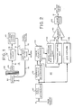
- Fig. 1 shows the major components of an anti-skid brake control system 10 which provides brake control for the brake 20 of the rotatable wheel 30.
- the system 10 includes a wheel speed transducer 40 which provides a sinusoidal signal on the line 41 having a frequency proportional to the angular velocity of the wheel 30.
- the signal on line 41 is shaped in a squaring circuit 50 and is then supplied as a wheel speed signal to an anti-skid control system 60 via line 51.
- the anti-skid control system 60 monitors the wheel signal on line 51.
- the anti-skid system 60 When the wheel signal indicates that the wheel 30 is about to go into a skid due to excessive braking force, the anti-skid system 60 generates a brake control signal on line 61.
- the anti-skid control valve 70 is positioned in the brake line 72 which supplies brake fluid under pressure to the brake 20, and the valve 70 operates in response to the signal on line 61 to reduce the brake pressure applied to the brake 20.
- the brake pressure in line 72 is the metered pressure determined by the vehicle operator by means of conventional hydraulic controls. As long as the wheel 30 is not braked so severely as to go into a skid, the full metered pressure on the line 72 is passed by the valve 70 via the line 74 to the brake 20. However, if the metered brake pressure exceeds the skid threshold and drives the wheel 30 into a skid, the anti-skid system 60 will generate a brake control signal on line 61 which causes the valve 70 to reduce the pressure in the line 74 to a value less than the metered pressure. By reducing the pressure .applied to the brake 30, the braking torque is reduced and the wheel 30 is prevented from skidding.
- Fig. 2 shows a schematic representation of the antiskid system 60 of Fig. 1, including a wheel speed determination unit 80 which receives the wheel signal on line 51 as an input and generates an output signal representative of measured wheel speed.
- This wheel speed signal is supplied as an input to a reference velocity determination unit 90 for generating a reference velocity signal.
- This reference velocity signal is supplied as an input to an apparatus 100 for determining an error velocity signal representative of the difference between the measured wheel speed signal and the reference velocity signal.
- the error velocity signal is applied as an input to two separate control units: the brake pressure bias modulation (PBM) unit, or modulator 110, and the transient control unit 120.
- PBM brake pressure bias modulation
- modulator 110 is described in detail below in connection with Figs. 3-6 and Tables 1-4.
- the modulator 110 generates a modulated brake control signal representative of the optimum braking pressure.
- the signal is smoothly, continuously modulated either to increase or to decrease the applied brake pressure to substantially prevent excessive wheel skidding while maintaining a high, effective level of braking.
- the output of the modulator 110 varies smoothly and continuously with time, it will on occasion be unable to respond quickly enough to prevent a wheel skid. For example, when a braked wheel suddenly enters a tar strip or an ice patch or a wet surface, the braking coefficient will abruptly fall and the modulator 110 may be unable to prevent a deep skid if the wheel 30 is heavily braked. Under these conditions, the transient control unit 120 responds to a large error velocity signal by commanding a sharp and sudden reduction in applied brake pressure.
- the wheel speed signal is also applied as an input to a lead network 130 which responds to changes in the wheel speed signal to anticipate trends and to command an early modification in brake pressure to anticipate skids.
- Outputs from the modulator 110, the transient control unit 120, and the lead network 130 are summed in a summing device 140 to produce a brake control signal which is amplified by the valve driver 150 and then applied as a control signal via line 61 to the antiskid control valve 70.
- the brake control system 10 is provided to set forth the environment of a preferred embodiment of the modulator of this invention.
- the modulator 110 individual components of this environment do not form a part of the present invention, and for that reason will not be described in detail here.
- those skilled in the art are familiar with various forms of these components.
- one form of the wheel speed determination unit 80, the error velocity determination unit 100, the modulator 110, and the transient control unit 120 is shown in United States Patent No. 3,724,916, issued April 3, 1973 to Edgar A. Hirzel, and entitled "Controlled Wheel Braking System".
- Other forms of the wheel speed determination unit 80 are described in United States Patent No. 4,056,287, issued November 1, 1977 to Wolfgang Gudat; in United States Patent No. 4,125,295, issued November 14, 1978 to Gerhard Ruhnam, et al.; and in U.S. Patent No. 4,184,203, issued January 15, 1980 to the inventor of the present invention.
- the present invention is directed to an improved modulator for a brake control system.
- the presently preferred embodiment of this invention included in modulator 110 of Fig. 2, will be described in conjunction with the flow charts of Figs. 3 and 4 and the graphs of Figs. 5 and 6.
- the presently preferred embodiment of this invention is implemented as a programmed microprocessor.
- the presently preferred microprocessor is a Z-80 CPU manufactured by Zilog, Inc., Cupertino, California.
- the program is presented in flow chart form in Figs. 3 and 4 and is listed in assembly language form in Tables 1-4.
- This program is executed periodically (203 times each second in the preferred embodiment) to generate a modulated brake control signal.
- This modulated brake control signal is then added to signals produced by the transient control unit 120 and the lead network 130, and the resulting signal is used to control the valve driver 150.
- the improved modulator of this invention can be used with a wide variety of brake control systems.
- This preferred embodiment utilizes two dynamic variables generated by the remainder of the brake control system.
- this preferred embodiment accepts as an input the most recent measurement of wheel velocity, which is labelled VELOC1 in the listings.
- VELOC1 is updated 203 times per second by the wheel speed determination unit 80.
- this embodiment accepts as an input the error velocity signal generated by the error velocity determination unit 100.
- This signal is labelled ERROR in the listings and V ERR in the flowcharts.
- ERROR corresponds generally to the algebraic difference between the reference velocity, as determined by the reference velocity determination unit 90, and the instantaneous wheel speed, as determined by the wheel speed determination unit 80.
- ERROR provides an indication of the slip velocity of the braked wheel 30.
- the modulator of this invention produces a modulated control signal which corresponds generally to the average level of brake pressure applied to the brake 20.
- a high modulator output corresponds to a high coefficient of friction between the wheel 30 and the pavement.
- the anti-skid valve 70 is generally designed to require a large current to bring about a large reduction in brake pressure, and therefore the driver 150 is designed to invert the signal from the summing device 140 prior to amplification to obtain the desired relationship between the modulated control signal and the valve control signal.
- the preferred embodiment of the improved modulator of this invention accepts generates a modulated brake control signal in response to these two dynamic variables.
- the first step in the program is to obtain the current error velocity.
- the VELOC1 velocity is used in the program flow charted in Fig. 4 to obtain the instantaneous threshold signal. As shown in Fig. 4, this is done by first obtaining the most recent wheel speed velocity measurement (VELOC1) and clamping VELOC1 to a maximum velocity if it exceeds that maximum velocity. Then the clamped VELOC1 is divided by 64 and the resulting value added to the beginning address of a look-up table.
- This look-up table is listed in Table 3, and it contains a plurality of threshold values. Depending on the instantaneous value of the pointer obtained from VELOC1, one of this plurality of threshold values is selected as the instantaneous threshold signal and stored in the variable SLIP.
- the program then adds the error velocity signal to the threshold signal and branches according to the sign and magnitude of the resulting sum. If the resulting sum is positive the program then selects one of five positive rate values in accordance with the size of the summation value. The selected rate is then added to the modulated control signal and the resulting sum is checked for overflow. If overflow has occurred, the modulated brake control signal is set to a maximum value.
- the resulting sum is compared with negative thresholds corresponding in magnitude to the four positive threshold values discussed above.
- the negative rate signal is then added to the modulated brake control signal, as shown in Fig. 6.
- the resulting sum is checked for overflow and set to zero if overflow is sensed.
- the modulated brake control signal is clamped to a minimum value and the clamped result is saved as the new modulated brake control signal.
- the disclosed program operates to generate a modulated brake control signal in response to an error velocity input signal and a wheel speed signal supplied by the remainder of the anti-skid system.
- the threshold signal varies as a function of wheel velocity. The relationship between these two variables is graphically depicted in Fig. 5. In Fig. 5, it can be seen that a low threshold of four-tenths of a foot per second is used for wheel velocities in the range of about 50 to about 120 feet per second. For wheel velocities either higher or lower than this range higher threshold signals are used.
- This variable threshold feature of the invention provides significant advantages in that the braking aggressiveness of the anti-skid system can be individually chosen for various wheel velocities.
- the curve of the Fig. 5 has been obtained through computer simulations. The approach used was to start with a uniformly low threshold signal and to raise the threshold signal in separate velocity ranges to the point where wheel skids became excessive in number.
- ground force during a computer simulated braking run is evaluated as a function of wheel velocity. If ground force supplied by the braking system becomes lower than optimum and the skid activity is not excessive, then the threshold for that velocity region can be raised. In this way, the braking aggressiveness of the modulator can be tailored to individual conditions and the need to compromise braking efficiency at one speed to obtain improved braking efficiency at another speed is eliminated.
- a second feature of this embodiment is that the velocity measurement VELOC1 is clamped to a maximum value before it is used as a pointer for table look-up purposes.
- This provides a fail safe feature in that a threshold value is obtained from the table even in the event of a malfunction causing the velocity measurement to read erroneously high.
- the table shown in Table 3 includes 37 distinct threshold values. In some applications it may be preferable to use a shorter table having half the resolution and approximately half the length of Table 3, thereby reducing memory requirements.
- Table 3 stores threshold values in units of tenths of feet per second.
- the first entry in Table 3 read BYTE 8. This indicates that the decimal number 8 is to be stored as the first entry in the table, and this entry corresponds to eight-tenths of a foot per second threshold velocity.
- the second column in the table reproduced in Table 3 indicates the range of velocities measured in feet per second which correspond to the individual entries of the table.
- the variables VELOC1 and ERROR are sixteen bit variables scaled to one-tenth of a foot per second per least significant bit.
- the variable PBM is directly related to brake pressure and inversely related to valve current. The relationship is linear such that full scale valve current corresponds to a PBM value of 1280 (hexadecimal) and zero valve current corresponds to a PBM value of 7FFF (hexadecimal).
- the invention can be used with acceleration based as well as velocity based modulators.
- the correspondence between wheel velocity and threshold, as well as other stored constants, can be chosen to fit other applications.
- the invention can be embodied in analog as well as digital forms; and other signals generally indicative of wheel speed, such as the reference velocity generated by the reference velocity determination unit 90, for example, can be used in place of the wheel speed signal to select the threshold signal.
Description
- This invention relates to an improved modulator for an anti-skid braking system, for modifying the action of a brake application means for a braked wheel of a vehicle said system including means for utilising information obtained from the rotation of said wheel to generate an input signal indicative of a braking condition; modulator means, responsive to the input signal, for generating a modulated brake control signal.
- One important class of modern anti-skid systems utilizes a modulator to provide a smoothly varying, continuous brake control signal. An early example of such systems is disclosed in U.S. Patent No. 3,724,916, issued April 3, 1973 to Edgar A. Hirzel and assigned to the assignee of the present invention. Such anti-skid systems have achieved a high level of commercial success, particularly for use with large jet transports such as the Boeing 727, 737 and 747 aircraft.
- The modulators in these anti-skid systems generate a modulated brake control signal as a time integral function of an input signal indicating a braking condition. In one type of modulator, the input signal is an error signal corresponding to the difference between measured wheel velocity and a reference velocity. This error signal is related to the slip velocity of the braked wheel and the pavement. In another type of modulator, the input signal corresponds to measured wheel deceleration. In either case, the modulated brake control signal varies smoothly and continuously as a time integral function of the input signal.
- In the past, such modulators have failed to provide an optimal level of flexibility and certain compromises have been necessary to design a modulator which provided the highest level of braking efficiency.
- The present invention is directed to an improved modulator which provides increased flexibility and braking efficiency.
- According to this invention, a modulator is provided with means for generating a threshold signal as a function of the velocity of the braked wheel. A rate signal is then generated as a function of both the threshold signal and the input signal discussed above, and a modulated brake control signal is generated as a time integral function of the rate signal.
- An important advantage of this invention is that it allows the modulator to be adjusted for optimally aggressive braking as a function of wheel velocity. The threshold value affects braking aggressiveness: a higher threshold value allows more aggressive braking before the modulator relaxes braking effort. Thus, by providing a variable threshold which is generated as a function of wheel speed, the present invention allows the threshold to be tailored to a particular aircraft-brake-landing gear combination as a function of wheel speed. Modulator efficiency is therefore more readily optimized at one speed regardless of the threshold requirements needed to optimize performance at another speed.
- The invention itself, together with further objects and attendant advantages, will best be understood by reference to the following detailed description taken in connection with the accompanying drawings.
- Figure 1 is a block diagram of a brake control system including an anti-skid control system.
- Figure 2 is a detailed block diagram of the functional components of the anti-skid control system of Fig. 1.
- Figure 3 is a flowchart of a portion of the brake pressure bias modulation (PBM) determination unit of Fig. 2.
- Figure 4 is a flowchart of a second portion of the PBM determination unit of Fig. 2.
- Figure 5 is a graph showing the functional relationship between the PBM threshold and wheel velocity in the preferred embodiment of Fig. 2.
- Figure 6 is a graph showing the functional relationship between the PBM rate and the sum of the error signal and the threshold signal in the preferred embodiment of Fig. 2.
- Referring now to the drawings, a preferred embodiment of the improved modulator of the present invention will be described in connection with the brake control system shown in Figs. 1 and 2. Fig. 1 shows the major components of an anti-skid
brake control system 10 which provides brake control for thebrake 20 of therotatable wheel 30. Thesystem 10 includes awheel speed transducer 40 which provides a sinusoidal signal on theline 41 having a frequency proportional to the angular velocity of thewheel 30. The signal online 41 is shaped in asquaring circuit 50 and is then supplied as a wheel speed signal to ananti-skid control system 60 vialine 51. Theanti-skid control system 60 monitors the wheel signal online 51. When the wheel signal indicates that thewheel 30 is about to go into a skid due to excessive braking force, theanti-skid system 60 generates a brake control signal online 61. Theanti-skid control valve 70 is positioned in thebrake line 72 which supplies brake fluid under pressure to thebrake 20, and thevalve 70 operates in response to the signal online 61 to reduce the brake pressure applied to thebrake 20. - In this preferred emodiment, the brake pressure in
line 72 is the metered pressure determined by the vehicle operator by means of conventional hydraulic controls. As long as thewheel 30 is not braked so severely as to go into a skid, the full metered pressure on theline 72 is passed by thevalve 70 via theline 74 to thebrake 20. However, if the metered brake pressure exceeds the skid threshold and drives thewheel 30 into a skid, theanti-skid system 60 will generate a brake control signal online 61 which causes thevalve 70 to reduce the pressure in theline 74 to a value less than the metered pressure. By reducing the pressure .applied to thebrake 30, the braking torque is reduced and thewheel 30 is prevented from skidding. - Fig. 2 shows a schematic representation of the
antiskid system 60 of Fig. 1, including a wheelspeed determination unit 80 which receives the wheel signal online 51 as an input and generates an output signal representative of measured wheel speed. This wheel speed signal is supplied as an input to a referencevelocity determination unit 90 for generating a reference velocity signal. This reference velocity signal is supplied as an input to anapparatus 100 for determining an error velocity signal representative of the difference between the measured wheel speed signal and the reference velocity signal. The error velocity signal is applied as an input to two separate control units: the brake pressure bias modulation (PBM) unit, ormodulator 110, and thetransient control unit 120. Themodulator 110 is described in detail below in connection with Figs. 3-6 and Tables 1-4. Here it is enough to state that themodulator 110 generates a modulated brake control signal representative of the optimum braking pressure. The signal is smoothly, continuously modulated either to increase or to decrease the applied brake pressure to substantially prevent excessive wheel skidding while maintaining a high, effective level of braking. - Because the output of the
modulator 110 varies smoothly and continuously with time, it will on occasion be unable to respond quickly enough to prevent a wheel skid. For example, when a braked wheel suddenly enters a tar strip or an ice patch or a wet surface, the braking coefficient will abruptly fall and themodulator 110 may be unable to prevent a deep skid if thewheel 30 is heavily braked. Under these conditions, thetransient control unit 120 responds to a large error velocity signal by commanding a sharp and sudden reduction in applied brake pressure. - The wheel speed signal is also applied as an input to a
lead network 130 which responds to changes in the wheel speed signal to anticipate trends and to command an early modification in brake pressure to anticipate skids. - Outputs from the
modulator 110, thetransient control unit 120, and thelead network 130 are summed in asumming device 140 to produce a brake control signal which is amplified by thevalve driver 150 and then applied as a control signal vialine 61 to theantiskid control valve 70. - The foregoing description of the
brake control system 10 is provided to set forth the environment of a preferred embodiment of the modulator of this invention. With the exception of themodulator 110, individual components of this environment do not form a part of the present invention, and for that reason will not be described in detail here. Furthermore, those skilled in the art are familiar with various forms of these components. For example, one form of the wheelspeed determination unit 80, the errorvelocity determination unit 100, themodulator 110, and thetransient control unit 120 is shown in United States Patent No. 3,724,916, issued April 3, 1973 to Edgar A. Hirzel, and entitled "Controlled Wheel Braking System". Other forms of the wheelspeed determination unit 80 are described in United States Patent No. 4,056,287, issued November 1, 1977 to Wolfgang Gudat; in United States Patent No. 4,125,295, issued November 14, 1978 to Gerhard Ruhnam, et al.; and in U.S. Patent No. 4,184,203, issued January 15, 1980 to the inventor of the present invention. - The present invention is directed to an improved modulator for a brake control system. The presently preferred embodiment of this invention, included in
modulator 110 of Fig. 2, will be described in conjunction with the flow charts of Figs. 3 and 4 and the graphs of Figs. 5 and 6. The presently preferred embodiment of this invention is implemented as a programmed microprocessor. The presently preferred microprocessor is a Z-80 CPU manufactured by Zilog, Inc., Cupertino, California. The program is presented in flow chart form in Figs. 3 and 4 and is listed in assembly language form in Tables 1-4. - This program is executed periodically (203 times each second in the preferred embodiment) to generate a modulated brake control signal. This modulated brake control signal is then added to signals produced by the
transient control unit 120 and thelead network 130, and the resulting signal is used to control thevalve driver 150. - As mentioned earlier, the improved modulator of this invention can be used with a wide variety of brake control systems. This preferred embodiment utilizes two dynamic variables generated by the remainder of the brake control system.
- First, this preferred embodiment accepts as an input the most recent measurement of wheel velocity, which is labelled VELOC1 in the listings. In this embodiment, VELOC1 is updated 203 times per second by the wheel
speed determination unit 80. - Second, this embodiment accepts as an input the error velocity signal generated by the error
velocity determination unit 100. This signal is labelled ERROR in the listings and VERR in the flowcharts. Here, ERROR corresponds generally to the algebraic difference between the reference velocity, as determined by the referencevelocity determination unit 90, and the instantaneous wheel speed, as determined by the wheelspeed determination unit 80. Thus, ERROR provides an indication of the slip velocity of the brakedwheel 30. - As a preliminary matter, it should be noted that the modulator of this invention produces a modulated control signal which corresponds generally to the average level of brake pressure applied to the
brake 20. Thus, a high modulator output corresponds to a high coefficient of friction between thewheel 30 and the pavement. In practice theanti-skid valve 70 is generally designed to require a large current to bring about a large reduction in brake pressure, and therefore thedriver 150 is designed to invert the signal from the summingdevice 140 prior to amplification to obtain the desired relationship between the modulated control signal and the valve control signal. - Turning now to Fig. 3, the preferred embodiment of the improved modulator of this invention accepts generates a modulated brake control signal in response to these two dynamic variables. As shown in Fig. 3, the first step in the program is to obtain the current error velocity. The VELOC1 velocity is used in the program flow charted in Fig. 4 to obtain the instantaneous threshold signal. As shown in Fig. 4, this is done by first obtaining the most recent wheel speed velocity measurement (VELOC1) and clamping VELOC1 to a maximum velocity if it exceeds that maximum velocity. Then the clamped VELOC1 is divided by 64 and the resulting value added to the beginning address of a look-up table. This look-up table is listed in Table 3, and it contains a plurality of threshold values. Depending on the instantaneous value of the pointer obtained from VELOC1, one of this plurality of threshold values is selected as the instantaneous threshold signal and stored in the variable SLIP.
- Returning to Fig. 3, the program then adds the error velocity signal to the threshold signal and branches according to the sign and magnitude of the resulting sum. If the resulting sum is positive the program then selects one of five positive rate values in accordance with the size of the summation value. The selected rate is then added to the modulated control signal and the resulting sum is checked for overflow. If overflow has occurred, the modulated brake control signal is set to a maximum value.
- If, on the other hand, the sum of the error velocity signal and the threshold signal is negative, the resulting sum is compared with negative thresholds corresponding in magnitude to the four positive threshold values discussed above. Depending on the negative magnitude of the sum, one of five possible negative rate signals is chosen and the negative rate signal is then added to the modulated brake control signal, as shown in Fig. 6. Again, the resulting sum is checked for overflow and set to zero if overflow is sensed. Finally, the modulated brake control signal is clamped to a minimum value and the clamped result is saved as the new modulated brake control signal.
- From the foregoing, it should be apparent that the disclosed program operates to generate a modulated brake control signal in response to an error velocity input signal and a wheel speed signal supplied by the remainder of the anti-skid system. One important feature of this preferred embodiment is that the threshold signal varies as a function of wheel velocity. The relationship between these two variables is graphically depicted in Fig. 5. In Fig. 5, it can be seen that a low threshold of four-tenths of a foot per second is used for wheel velocities in the range of about 50 to about 120 feet per second. For wheel velocities either higher or lower than this range higher threshold signals are used.
- This variable threshold feature of the invention provides significant advantages in that the braking aggressiveness of the anti-skid system can be individually chosen for various wheel velocities. The curve of the Fig. 5 has been obtained through computer simulations. The approach used was to start with a uniformly low threshold signal and to raise the threshold signal in separate velocity ranges to the point where wheel skids became excessive in number. Preferably, ground force during a computer simulated braking run is evaluated as a function of wheel velocity. If ground force supplied by the braking system becomes lower than optimum and the skid activity is not excessive, then the threshold for that velocity region can be raised. In this way, the braking aggressiveness of the modulator can be tailored to individual conditions and the need to compromise braking efficiency at one speed to obtain improved braking efficiency at another speed is eliminated.
- A second feature of this embodiment is that the velocity measurement VELOC1 is clamped to a maximum value before it is used as a pointer for table look-up purposes. This provides a fail safe feature in that a threshold value is obtained from the table even in the event of a malfunction causing the velocity measurement to read erroneously high. The table shown in Table 3 includes 37 distinct threshold values. In some applications it may be preferable to use a shorter table having half the resolution and approximately half the length of Table 3, thereby reducing memory requirements.
- By way of explanation, Table 3 stores threshold values in units of tenths of feet per second. For example, the first entry in Table 3 read
BYTE 8. This indicates that thedecimal number 8 is to be stored as the first entry in the table, and this entry corresponds to eight-tenths of a foot per second threshold velocity. The second column in the table reproduced in Table 3 indicates the range of velocities measured in feet per second which correspond to the individual entries of the table. The variables VELOC1 and ERROR are sixteen bit variables scaled to one-tenth of a foot per second per least significant bit. Additionally, the variable PBM is directly related to brake pressure and inversely related to valve current. The relationship is linear such that full scale valve current corresponds to a PBM value of 1280 (hexadecimal) and zero valve current corresponds to a PBM value of 7FFF (hexadecimal). - Of course, it should be understood that various changes and modifications to the preferred embodiment described above will be apparent to those skilled in the art. For example, the invention can be used with acceleration based as well as velocity based modulators. In addition, the correspondence between wheel velocity and threshold, as well as other stored constants, can be chosen to fit other applications. The invention can be embodied in analog as well as digital forms; and other signals generally indicative of wheel speed, such as the reference velocity generated by the reference
velocity determination unit 90, for example, can be used in place of the wheel speed signal to select the threshold signal. Such changes and modifications can be made without departing from the spirit and scope of the present invention, and without diminishing its attendant advantages. It is therefore intended that such changes and modifications be covered by the following claims.


Claims (9)
Applications Claiming Priority (2)
| Application Number | Priority Date | Filing Date | Title |
|---|---|---|---|
| US06/147,386 US4338669A (en) | 1980-05-07 | 1980-05-07 | Modulator for anti-skid braking system |
| US147386 | 1980-05-07 |
Publications (3)
| Publication Number | Publication Date |
|---|---|
| EP0039606A2 EP0039606A2 (en) | 1981-11-11 |
| EP0039606A3 EP0039606A3 (en) | 1983-06-01 |
| EP0039606B1 true EP0039606B1 (en) | 1987-01-07 |
Family
ID=22521369
Family Applications (1)
| Application Number | Title | Priority Date | Filing Date |
|---|---|---|---|
| EP81301955A Expired EP0039606B1 (en) | 1980-05-07 | 1981-05-01 | Improved modulator for anti-skid braking system |
Country Status (3)
| Country | Link |
|---|---|
| US (1) | US4338669A (en) |
| EP (1) | EP0039606B1 (en) |
| DE (1) | DE3175799D1 (en) |
Families Citing this family (8)
| Publication number | Priority date | Publication date | Assignee | Title |
|---|---|---|---|---|
| US4562542A (en) * | 1980-05-07 | 1985-12-31 | Crane Co. | Modulator for anti-skid braking system |
| DE3435864A1 (en) * | 1984-09-29 | 1986-04-10 | Robert Bosch Gmbh, 7000 Stuttgart | METHOD FOR CENTRALLY DETERMINING A REFERENCE SIGNAL APPROXIMATE WITH VEHICLE SPEED |
| JPH04110264A (en) * | 1990-08-30 | 1992-04-10 | Sumitomo Electric Ind Ltd | Antilok controller equipped with learning correcting function |
| US5547267A (en) * | 1995-02-03 | 1996-08-20 | Kelsey-Hayes Company | Method and system for antilock braking on a deformable surface |
| WO1998052803A1 (en) * | 1997-05-22 | 1998-11-26 | Japan Electronics Industry Ltd. | Abs device |
| US7509204B2 (en) * | 2005-02-11 | 2009-03-24 | Honeywell International Inc. | Method and system using tire stretch data to control braking |
| DE102009009339A1 (en) * | 2009-02-17 | 2010-08-26 | Khs Ag | Filling element for filling bottles or similar containers and filling machine with such filling elements |
| US10234837B2 (en) * | 2015-09-28 | 2019-03-19 | Deere & Company | Adaptive performance targets for controlling a mobile machine |
Family Cites Families (14)
| Publication number | Priority date | Publication date | Assignee | Title |
|---|---|---|---|---|
| US3523712A (en) * | 1966-11-16 | 1970-08-11 | Teldix Gmbh | Vehicle brake control system for preventing wheel locking |
| US3727992A (en) * | 1971-03-15 | 1973-04-17 | Gen Motors Corp | Anti-lock brake control system |
| US3724916A (en) * | 1971-06-21 | 1973-04-03 | Crane Co | Controlled wheel braking system |
| US3842355A (en) * | 1972-01-17 | 1974-10-15 | Wagner Electric Corp | Signal processing circuit for wheel slip control systems |
| US4212499A (en) * | 1972-02-25 | 1980-07-15 | Texas Instruments Incorporated | Vehicle velocity ramp generator in a skid control vehicle braking system |
| DE2243778C3 (en) * | 1972-09-06 | 1980-08-07 | Wabco Fahrzeugbremsen Gmbh, 3000 Hannover | Circuit arrangement for anti-lock systems |
| US3838890A (en) * | 1973-03-19 | 1974-10-01 | Gen Motors Corp | Adaptive anti-lock brake control |
| IT991874B (en) * | 1973-07-26 | 1975-08-30 | Fiat Spa | IMPROVEMENT OF ANTI-LOCK BRAKING SYSTEMS FOR VEHICLES |
| US3953080A (en) * | 1973-11-28 | 1976-04-27 | General Motors Corporation | Adaptive anti-lock brake control system |
| US3964796A (en) * | 1975-03-27 | 1976-06-22 | General Motors Corporation | Adaptive anti-lock brake control apparatus |
| US4068903A (en) * | 1976-12-08 | 1978-01-17 | The United States Of America As Represented By The Secretary Of The Air Force | Adaptive skid detector threshold apparatus |
| DE2701456A1 (en) * | 1977-01-14 | 1978-07-20 | Knorr Bremse Gmbh | ANTI-BLOCK PROTECTION DEVICE FOR VEHICLES, IN PARTICULAR RAIL VEHICLES |
| US4076332A (en) * | 1977-01-24 | 1978-02-28 | General Motors Corporation | Wheel lock control circuit |
| JPS6042056B2 (en) * | 1978-07-21 | 1985-09-20 | 本田技研工業株式会社 | Anti skid brake device |
-
1980
- 1980-05-07 US US06/147,386 patent/US4338669A/en not_active Expired - Lifetime
-
1981
- 1981-05-01 EP EP81301955A patent/EP0039606B1/en not_active Expired
- 1981-05-01 DE DE8181301955T patent/DE3175799D1/en not_active Expired
Also Published As
| Publication number | Publication date |
|---|---|
| US4338669A (en) | 1982-07-06 |
| DE3175799D1 (en) | 1987-02-12 |
| EP0039606A3 (en) | 1983-06-01 |
| EP0039606A2 (en) | 1981-11-11 |
Similar Documents
| Publication | Publication Date | Title |
|---|---|---|
| US7128377B2 (en) | System and method for adaptive brake application and initial skid detection | |
| US7837279B2 (en) | System and method for adaptive brake application and initial skid detection | |
| US4562542A (en) | Modulator for anti-skid braking system | |
| EP0039606B1 (en) | Improved modulator for anti-skid braking system | |
| US4543633A (en) | Modulator for anti-skid braking system | |
| EP0039605B1 (en) | Improved modulator for anti-skid braking system | |
| EP0036719B1 (en) | Initialization apparatus for a brake control system | |
| US4484281A (en) | Apparatus for generating a lead signal in an antiskid system | |
| US4484282A (en) | Apparatus for generating a lead signal in an antiskid system | |
| EP0039602B1 (en) | Improved apparatus for generating a lead signal in an antiskid system | |
| US4479185A (en) | Apparatus for generating a lead signal in an antiskid system | |
| EP0039607B1 (en) | Improved apparatus for generating a lead signal in an antiskid system | |
| EP0048309B1 (en) | Apparatus for generating a reference signal in a brake control system | |
| EP0039604B1 (en) | Anti-skid system for vehicle brakes | |
| EP0247640B1 (en) | Apparatus for generating a reference signal in a brake control system |
Legal Events
| Date | Code | Title | Description |
|---|---|---|---|
| PUAI | Public reference made under article 153(3) epc to a published international application that has entered the european phase |
Free format text: ORIGINAL CODE: 0009012 |
|
| AK | Designated contracting states |
Designated state(s): DE FR GB |
|
| PUAL | Search report despatched |
Free format text: ORIGINAL CODE: 0009013 |
|
| AK | Designated contracting states |
Designated state(s): DE FR GB |
|
| 17P | Request for examination filed |
Effective date: 19830919 |
|
| GRAA | (expected) grant |
Free format text: ORIGINAL CODE: 0009210 |
|
| AK | Designated contracting states |
Kind code of ref document: B1 Designated state(s): DE FR GB |
|
| ET | Fr: translation filed | ||
| REF | Corresponds to: |
Ref document number: 3175799 Country of ref document: DE Date of ref document: 19870212 |
|
| PLBE | No opposition filed within time limit |
Free format text: ORIGINAL CODE: 0009261 |
|
| STAA | Information on the status of an ep patent application or granted ep patent |
Free format text: STATUS: NO OPPOSITION FILED WITHIN TIME LIMIT |
|
| 26N | No opposition filed | ||
| PGFP | Annual fee paid to national office [announced via postgrant information from national office to epo] |
Ref country code: FR Payment date: 20000419 Year of fee payment: 20 |
|
| PGFP | Annual fee paid to national office [announced via postgrant information from national office to epo] |
Ref country code: GB Payment date: 20000420 Year of fee payment: 20 Ref country code: DE Payment date: 20000420 Year of fee payment: 20 |
|
| PG25 | Lapsed in a contracting state [announced via postgrant information from national office to epo] |
Ref country code: GB Free format text: LAPSE BECAUSE OF EXPIRATION OF PROTECTION Effective date: 20010430 |
|
| REG | Reference to a national code |
Ref country code: GB Ref legal event code: PE20 Effective date: 20010430 |