EP0039599B1 - Integral end closure and hub for a ball valve body - Google Patents
Integral end closure and hub for a ball valve body Download PDFInfo
- Publication number
- EP0039599B1 EP0039599B1 EP81301947A EP81301947A EP0039599B1 EP 0039599 B1 EP0039599 B1 EP 0039599B1 EP 81301947 A EP81301947 A EP 81301947A EP 81301947 A EP81301947 A EP 81301947A EP 0039599 B1 EP0039599 B1 EP 0039599B1
- Authority
- EP
- European Patent Office
- Prior art keywords
- end closure
- valve
- hub
- ball
- flange portion
- Prior art date
- Legal status (The legal status is an assumption and is not a legal conclusion. Google has not performed a legal analysis and makes no representation as to the accuracy of the status listed.)
- Expired
Links
- 229910000831 Steel Inorganic materials 0.000 claims description 17
- 239000010959 steel Substances 0.000 claims description 17
- 238000004519 manufacturing process Methods 0.000 description 8
- 239000002184 metal Substances 0.000 description 8
- 239000000835 fiber Substances 0.000 description 6
- 238000000034 method Methods 0.000 description 6
- 238000003466 welding Methods 0.000 description 6
- 238000003754 machining Methods 0.000 description 5
- 238000005520 cutting process Methods 0.000 description 3
- 239000012530 fluid Substances 0.000 description 3
- 238000009434 installation Methods 0.000 description 3
- 239000000463 material Substances 0.000 description 3
- 238000007789 sealing Methods 0.000 description 3
- 230000015572 biosynthetic process Effects 0.000 description 2
- 238000005242 forging Methods 0.000 description 2
- 238000005096 rolling process Methods 0.000 description 2
- 230000000295 complement effect Effects 0.000 description 1
- 238000010276 construction Methods 0.000 description 1
- 230000001419 dependent effect Effects 0.000 description 1
- 230000000694 effects Effects 0.000 description 1
- 230000008030 elimination Effects 0.000 description 1
- 238000003379 elimination reaction Methods 0.000 description 1
- 230000007613 environmental effect Effects 0.000 description 1
- 210000004907 gland Anatomy 0.000 description 1
- 238000007689 inspection Methods 0.000 description 1
- 238000005058 metal casting Methods 0.000 description 1
- 239000002699 waste material Substances 0.000 description 1
Images

Classifications
-
- F—MECHANICAL ENGINEERING; LIGHTING; HEATING; WEAPONS; BLASTING
- F16—ENGINEERING ELEMENTS AND UNITS; GENERAL MEASURES FOR PRODUCING AND MAINTAINING EFFECTIVE FUNCTIONING OF MACHINES OR INSTALLATIONS; THERMAL INSULATION IN GENERAL
- F16K—VALVES; TAPS; COCKS; ACTUATING-FLOATS; DEVICES FOR VENTING OR AERATING
- F16K27/00—Construction of housing; Use of materials therefor
- F16K27/06—Construction of housing; Use of materials therefor of taps or cocks
- F16K27/067—Construction of housing; Use of materials therefor of taps or cocks with spherical plugs
-
- B—PERFORMING OPERATIONS; TRANSPORTING
- B21—MECHANICAL METAL-WORKING WITHOUT ESSENTIALLY REMOVING MATERIAL; PUNCHING METAL
- B21K—MAKING FORGED OR PRESSED METAL PRODUCTS, e.g. HORSE-SHOES, RIVETS, BOLTS OR WHEELS
- B21K1/00—Making machine elements
- B21K1/20—Making machine elements valve parts
Definitions
- This invention relates to an integral valve end closure and hub for a fluid flow control valve and to a method of making such end closure and hub.
- valve bodies and other pressure vessels from rolled steel shapes, wherein the material is generally denser and of greater uniformity than can usually be achieved with metal castings.
- ball valves, check valves and fluid flow control valves are commonly formed with a main body band of cylindrical or spherical configuration, with at least one full size end opening through which a ball, clapper, plug or other closure member can be inserted. In completing fabrication, this opening is covered with an end closure carrying a hub for attaching the valve member into a pipeline.
- An end closure which has been formed by uni- directional swaging in accordance with the invention, as well as having the manufacturing advantages over the prior art specified above with the elimination of extensive welding also provides a stronger structure in that the end closure has a very strong metal fibre orientation internally because of the small flow-lines of the metal caused during the unidirectional swaging manufacture thereof.
- DE-B-2032132 there has been disclosed a method of forming an end closure in the manufacture of a valve body in which the end closure is formed from a single thick flat steel plate which is swaged axially of a central flow passage through the closure to form a hub portion for connection to a pipeline with a valve seat being provided on the interior of the end closure. While this method does provide a one piece end closure formed, rather than machine welded, from a single metal plate, it uses swaging operations carried in opposite directions with the consequential reverse flow deformation of the metal causing the flow lines in the metal during formation to be distorted leading to a reduction in the overall strength of the finished end portion.
- valves may be of the large size to which the present invention is applicable, for example for use with pipelines of a metre or more in diameter when the forces tending to distort the valve body in use thereof can be very large indeed.
- DE-B-2032132 of the advantages achievable by controlled grain orientation despite the fact that in other fields of manufacture the desirability of controlling the internal grain structure has been appreciated as disclosed in connection with a forging operation in, for example, US-A-4168619.
- Rolled steel has a uni-directional grain orientation and with the hubs being swaged from the same steel plate with the swaging being uni- directional there is a continuity of fibre orientation from the outer circumference of the flange portion, through the tapered portion, to the end of the cylindrical hub portion.
- This continuity of fibre orientation gives a considerable increase of strength as compared with the lack of such fibre orientation and this emphasizes the advantage over the prior welded end portion constructions previously used in very large sized valves prepared for pipeline usage.
- the inner surface of the end closure can be made to follow quite closely with the outer surface of a valve ball and can also readily have a recess cut therein for the receipt of a seal assembly, this recess being cut in the portion of the end closure which is least subject to stress with the more highly stressed portions of the end closure being at the points of merger of the hub and flange with the tapered portion, these points of merger being unweakened and provided with a smooth continuity of fibre orientation therethrough.
- the ball valve end closures are formed from plate in two stages, a first stage forming the flange and tapered portions with a hub portion having a slightly tapered inner surface and a second, finishing stage, in which a spherical ball is forced through the workpiece to expand the interior surface of the hub portion into cylindrical form.
- the swaging operation is carried out by forcing a tapered male die of circular cross-section through a central opening in the plate; then placing the plate in a female die having a lower inner surface of generally cylindrical configuration; and then forcing a male finishing die having a maximum circular cross-section the diameter to which corresponds generally to the desired inner diameter of the hub portion and a smaller leading cross-section of increasing diameter to the maximum diameter.
- the male finishing die may be a simple sphere and good results are found to be achieved when a tapered die has a slightly tapered leading portion to form the hub portion nearly cylindrical, and a sharply tapered trailing portion.
- a valve having end closures 10 provided with integral hubs 10a the ends of which have been adapted for installation in a pipeline by machining them for welding.
- the integral structures are shown as principal components of a ball valve 11 of a type which is widely sold for pipeline installations.
- the ball valve 11 includes a main body band 12 of cylindrical configuration formed by rolling up a steel plate, and the end closures are secured directly to the body band by means of a plurality of studs 13, which are threaded into the tapped openings around the annular end 14 of the body.
- the end closures 10 are placed over the studs 13 with a flange surface 16 thereon engaging the annular body band end surfaces. Nuts 18 are tightened against the outer flange surface 19 to secure the end closures 10 in place.
- a seal ring 15 around the annular end 14 renders the structure 12 fluid tight.
- one end closure 10 with seat ring assembly 41 therein is secured to the body band 12 as just described.
- a valve ball 20 which may be cast has been machined at 22 to form a smooth, highly polished spherical outer surface and at 24, to finish upper and lower journals 26 and 28 which are formed integral with the ball 20.
- Top and bottom bearing blocks 30 and 31, each with suitable bushings 32, are placed over the journals 26 and 28 and the entire assembly is inserted into the open end of the body band 12.
- a stem 34 is inserted through a top opening 36 in the body band, is coupled to the upper trunnion 26 by means of pins 37. Finally, a gland plate 38 with suitable sealing means to seal around it, as well as around the stem 34, together with a valve operator mounting plate 39, are secured in place by means of cap screws 40.
- the seat rings 41 with suitable seal rings 42 and 49 for sealing against the valve ball 20 and the end closure 10, respectively, are inserted in place in recesses 45 in the end closure, against biasing sprinqs 46.
- the second end closure is mounted on the main body band and bolted to the annular end thereof, as previously described.
- an extended face 48 on the end closure clamps firmly against the bearing blocks 30 and 31 which are positioned relative to the end closure by pins 50.
- the end closure 10 is formed by cutting a circular work-piece 51 of rolled steel plate through which a small coaxial, circular opening 52 is cut.
- the work-piece 51 is placed in a female die 60 having a generally planar outer support surface 62, which merges into a sharply flared upper conical surface 64, and then into a slightly tapered lower surface 66.
- a male die 70 having male surfaces 72, 74 and 76, which are complementary to the inner surfaces 62, 64 and 66 of the female die, and a sharply tapered end portion 78.
- the work-piece 51 is heated to glowing and placed in the die 60.
- the die 70 is driven down to swage the steel around the small center opening 52 to a configuration following the contours of the dies 60 and 70.
- the work-piece 51 which will ultimately become an end closure 10, retains a flat, planar outer portion 80 for attachment to the body band 12 and then tapers sharply at 82 into a smaller diameter and then more gradually at 84 to a diameter slightly less than the ultimate pipeline diameter.
- annular portion 48 of the end closure 10 which clamps and secures the bearing blocks 30 and 32 is somewhat thicker than the annular radially outward portion 85 shown in Figure 4, some machining can be saved, and the strength in the area of the bolting circle enhanced, by compressing the outer annular portion 85 of the work-piece 51 by forging with an annular die 72a. This both reduces the thickness of the radially outward portion 85 and improves the grain flow lines of the outer portion 85.
- the final swaging operation is done in a second female die 60a again having a flat, planar outer support surface 62a and a rather sharply tapered outer portion 64a.
- this sharply tapered portion 64a merges directly into a substantially cylindrical opening 88 adapted to accommodate a male die of circular cross-section.
- a sphere 90 of a diameter substantially equal to the desired inner hub diameter may be forced through the workpiece 51 to dilate the previously tapered outer portion of the work-piece into the cylindrical configuration shown.
- the work-piece 50 undergoes machining operations for removal of material, as indicated by dotted lines, to form the bolting flange surface 16 and 18, the bearing block clamping surfaces 48, and the seat ring recesses 45.
- the method also eliminates the need to form a separate cylindrical hub which, when formed by rolling a flat plate, required a welding operation to form a seam between the ends, which were rolled together. Further, the method eliminates the need to machine both the flat plate and the cylindrical hub to prepare them for welding, and it eliminates the welding operation itself, not to mention the extensive weld tests and inspections that are required for safety and environmental purposes. After preparing the work-piece, the end closure with integral hub is formed forfinish machining by two successive swaging operations.
- the hub so formed has the strength and simplicity of an integral structure, and being formed from rolled steel plate it has the fiber structure common to rolled steel flowing in continuity from the outer periphery of the end closure 10, along the hub portion 84 to the pipeline connection end 1 Oa.
- the funnel shape of the end closure may provide greater strength and, by cutting seat ring recesses 45 in the tapered portion 82, they are displaced from the planar outer surfaces 16 and 48. This enables use of a narrower body band 12, effecting a further saving in metal.
Landscapes
- Engineering & Computer Science (AREA)
- Mechanical Engineering (AREA)
- General Engineering & Computer Science (AREA)
- Valve Housings (AREA)
- Forging (AREA)
Description
- This invention relates to an integral valve end closure and hub for a fluid flow control valve and to a method of making such end closure and hub.
- It has been found highly advantageous, where possible, to form large diameter valve bodies and other pressure vessels from rolled steel shapes, wherein the material is generally denser and of greater uniformity than can usually be achieved with metal castings. For example, ball valves, check valves and fluid flow control valves are commonly formed with a main body band of cylindrical or spherical configuration, with at least one full size end opening through which a ball, clapper, plug or other closure member can be inserted. In completing fabrication, this opening is covered with an end closure carrying a hub for attaching the valve member into a pipeline. When forming the end closure of steel plates, it is conventional practice to form it in at least two pieces, one a flat plate with a large central opening which is bolted or otherwise secured to a main body member, and the other a cylindrical pipe which is welded into the opening for installation in a pipeline. Often, recesses are cut into the flat plate to accommodate sealing rings which engage against the valve member to effect a seal. The main body member, then, must be wide enough to cover at least the great majority of the width of the valve member and span the space between the two flat inner surfaces of the opposing end closures. Such a ball valve, in accordance with the prior art portion of claim 1 is disclosed in US-A-3,737,145.
- It is an object of this invention as claimed in claim 1, to provide a valve body end closure which uses, without waste, virtually all of the metal of a circular plate section, there being provided a one-piece valve end closure and hub of plate steel which eliminates the extensive welding operation which would otherwise be required to secure a cylindrical hub to the plate.
- An end closure which has been formed by uni- directional swaging in accordance with the invention, as well as having the manufacturing advantages over the prior art specified above with the elimination of extensive welding also provides a stronger structure in that the end closure has a very strong metal fibre orientation internally because of the small flow-lines of the metal caused during the unidirectional swaging manufacture thereof.
- In DE-B-2032132 there has been disclosed a method of forming an end closure in the manufacture of a valve body in which the end closure is formed from a single thick flat steel plate which is swaged axially of a central flow passage through the closure to form a hub portion for connection to a pipeline with a valve seat being provided on the interior of the end closure. While this method does provide a one piece end closure formed, rather than machine welded, from a single metal plate, it uses swaging operations carried in opposite directions with the consequential reverse flow deformation of the metal causing the flow lines in the metal during formation to be distorted leading to a reduction in the overall strength of the finished end portion. While this is not of great importance in small valves where the amount of metal used is of no great importance, it is of great importance where the valves may be of the large size to which the present invention is applicable, for example for use with pipelines of a metre or more in diameter when the forces tending to distort the valve body in use thereof can be very large indeed. There is no appreciation at all in DE-B-2032132 of the advantages achievable by controlled grain orientation despite the fact that in other fields of manufacture the desirability of controlling the internal grain structure has been appreciated as disclosed in connection with a forging operation in, for example, US-A-4168619. Rolled steel has a uni-directional grain orientation and with the hubs being swaged from the same steel plate with the swaging being uni- directional there is a continuity of fibre orientation from the outer circumference of the flange portion, through the tapered portion, to the end of the cylindrical hub portion. This continuity of fibre orientation gives a considerable increase of strength as compared with the lack of such fibre orientation and this emphasizes the advantage over the prior welded end portion constructions previously used in very large sized valves prepared for pipeline usage. Further, with the unobstructed tapered portion the inner surface of the end closure can be made to follow quite closely with the outer surface of a valve ball and can also readily have a recess cut therein for the receipt of a seal assembly, this recess being cut in the portion of the end closure which is least subject to stress with the more highly stressed portions of the end closure being at the points of merger of the hub and flange with the tapered portion, these points of merger being unweakened and provided with a smooth continuity of fibre orientation therethrough.
- Preferably the ball valve end closures are formed from plate in two stages, a first stage forming the flange and tapered portions with a hub portion having a slightly tapered inner surface and a second, finishing stage, in which a spherical ball is forced through the workpiece to expand the interior surface of the hub portion into cylindrical form. In a particularly exemplified method which has been found to give very good results in practice in the production of large sized ball valves the swaging operation is carried out by forcing a tapered male die of circular cross-section through a central opening in the plate; then placing the plate in a female die having a lower inner surface of generally cylindrical configuration; and then forcing a male finishing die having a maximum circular cross-section the diameter to which corresponds generally to the desired inner diameter of the hub portion and a smaller leading cross-section of increasing diameter to the maximum diameter. Suitably the male finishing die may be a simple sphere and good results are found to be achieved when a tapered die has a slightly tapered leading portion to form the hub portion nearly cylindrical, and a sharply tapered trailing portion.
- Particular embodiments of the invention are set out in the dependent claims.
- The invention will be further described, by way of example, with reference to the accompanying drawings, wherein:
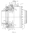
- FIGURE 1 is an elevation view, half in section, of a ball valve embodying the invention;
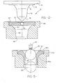
- FIGURES 2, and 4 are schematic views in section showing three stages of an initial swaging operation in the manufacture of part of the valve body of the valve of Figure 1;
- FIGURE 5 is a schematic view in section showing a subsequent swaging operation; and
- FIGURE 6 is a schematic section view, illustrating the removal of material in subsequent machining operations to complete the end closure.
- Referring now to Figure 1 a valve is shown having
end closures 10 provided withintegral hubs 10a the ends of which have been adapted for installation in a pipeline by machining them for welding. The integral structures are shown as principal components of a ball valve 11 of a type which is widely sold for pipeline installations. The ball valve 11 includes amain body band 12 of cylindrical configuration formed by rolling up a steel plate, and the end closures are secured directly to the body band by means of a plurality ofstuds 13, which are threaded into the tapped openings around theannular end 14 of the body. Theend closures 10 are placed over thestuds 13 with aflange surface 16 thereon engaging the annular body band end surfaces.Nuts 18 are tightened against theouter flange surface 19 to secure theend closures 10 in place. Aseal ring 15 around theannular end 14 renders thestructure 12 fluid tight. - In practice, one
end closure 10 withseat ring assembly 41 therein, is secured to thebody band 12 as just described. Avalve ball 20 which may be cast has been machined at 22 to form a smooth, highly polished spherical outer surface and at 24, to finish upper andlower journals ball 20. Top and bottom bearingblocks suitable bushings 32, are placed over thejournals body band 12. - A
stem 34 is inserted through a top opening 36 in the body band, is coupled to theupper trunnion 26 by means ofpins 37. Finally, agland plate 38 with suitable sealing means to seal around it, as well as around thestem 34, together with a valveoperator mounting plate 39, are secured in place by means ofcap screws 40. - In completing the fabricating operation, the
seat rings 41 withsuitable seal rings valve ball 20 and theend closure 10, respectively, are inserted in place inrecesses 45 in the end closure, against biasingsprinqs 46. Then the second end closure is mounted on the main body band and bolted to the annular end thereof, as previously described. When so secured an extendedface 48 on the end closure clamps firmly against thebearing blocks pins 50. - Referring now to Figures 2 to 4 the
end closure 10 is formed by cutting a circular work-piece 51 of rolled steel plate through which a small coaxial,circular opening 52 is cut. The work-piece 51 is placed in afemale die 60 having a generally planarouter support surface 62, which merges into a sharply flared upperconical surface 64, and then into a slightly taperedlower surface 66. Cooperating with the female die is amale die 70 havingmale surfaces inner surfaces tapered end portion 78. - In formation, the work-
piece 51 is heated to glowing and placed in the die 60. The die 70 is driven down to swage the steel around the small center opening 52 to a configuration following the contours of thedies piece 51, which will ultimately become anend closure 10, retains a flat, planarouter portion 80 for attachment to thebody band 12 and then tapers sharply at 82 into a smaller diameter and then more gradually at 84 to a diameter slightly less than the ultimate pipeline diameter. - Since, as shown in Figure 1, that
annular portion 48 of theend closure 10 which clamps and secures thebearing blocks portion 85 shown in Figure 4, some machining can be saved, and the strength in the area of the bolting circle enhanced, by compressing the outerannular portion 85 of the work-piece 51 by forging with anannular die 72a. This both reduces the thickness of the radiallyoutward portion 85 and improves the grain flow lines of theouter portion 85. - Referring now to Figure 5, the final swaging operation is done in a
second female die 60a again having a flat, planarouter support surface 62a and a rather sharply taperedouter portion 64a. However, this sharplytapered portion 64a merges directly into a substantiallycylindrical opening 88 adapted to accommodate a male die of circular cross-section. For example, asphere 90 of a diameter substantially equal to the desired inner hub diameter may be forced through theworkpiece 51 to dilate the previously tapered outer portion of the work-piece into the cylindrical configuration shown. - Finally, as shown in Figure 6, the work-
piece 50 undergoes machining operations for removal of material, as indicated by dotted lines, to form the boltingflange surface block clamping surfaces 48, and the seat ring recesses 45. - It will be noted that, in forming an
end closure 10 as described above a muchsmaller hole 52 than was required in previous forming methods is cut through the work-piece 50. This reduces cutting time and it saves a quantity of steel that was often wasted previously. The method also eliminates the need to form a separate cylindrical hub which, when formed by rolling a flat plate, required a welding operation to form a seam between the ends, which were rolled together. Further, the method eliminates the need to machine both the flat plate and the cylindrical hub to prepare them for welding, and it eliminates the welding operation itself, not to mention the extensive weld tests and inspections that are required for safety and environmental purposes. After preparing the work-piece, the end closure with integral hub is formed forfinish machining by two successive swaging operations. - The hub so formed has the strength and simplicity of an integral structure, and being formed from rolled steel plate it has the fiber structure common to rolled steel flowing in continuity from the outer periphery of the
end closure 10, along thehub portion 84 to the pipeline connection end 1 Oa. - The funnel shape of the end closure may provide greater strength and, by cutting seat ring recesses 45 in the
tapered portion 82, they are displaced from the planarouter surfaces narrower body band 12, effecting a further saving in metal.
Claims (3)
Applications Claiming Priority (2)
| Application Number | Priority Date | Filing Date | Title |
|---|---|---|---|
| US06/146,764 US4339112A (en) | 1980-05-05 | 1980-05-05 | Integral end closure and hub for valve body and method of forming same |
| US146764 | 1980-05-05 |
Publications (2)
| Publication Number | Publication Date |
|---|---|
| EP0039599A1 EP0039599A1 (en) | 1981-11-11 |
| EP0039599B1 true EP0039599B1 (en) | 1985-08-28 |
Family
ID=22518914
Family Applications (1)
| Application Number | Title | Priority Date | Filing Date |
|---|---|---|---|
| EP81301947A Expired EP0039599B1 (en) | 1980-05-05 | 1981-05-01 | Integral end closure and hub for a ball valve body |
Country Status (4)
| Country | Link |
|---|---|
| US (1) | US4339112A (en) |
| EP (1) | EP0039599B1 (en) |
| CA (1) | CA1147711A (en) |
| DE (1) | DE3171992D1 (en) |
Families Citing this family (5)
| Publication number | Priority date | Publication date | Assignee | Title |
|---|---|---|---|---|
| US4545231A (en) * | 1982-08-16 | 1985-10-08 | Grove Valve & Regulator Company | Method of manufacturing a weld neck flange |
| US5159826A (en) * | 1990-07-19 | 1992-11-03 | Hidaka Seiki Kabushiki Kaisha | Die set for manufacturing fins of heat exchangers and a manufacturing device using the same |
| CN1329682C (en) * | 2002-01-18 | 2007-08-01 | 斯瓦戈洛克公司 | Ball valve with integral packing |
| US8511640B2 (en) * | 2009-12-22 | 2013-08-20 | Hydac Accessories Gmbh | Ball valve with detachable slide bearing bushes |
| NO334904B1 (en) * | 2013-02-06 | 2014-07-07 | Sitek As | butterfly valve |
Citations (3)
| Publication number | Priority date | Publication date | Assignee | Title |
|---|---|---|---|---|
| FR1100159A (en) * | 1954-02-26 | 1955-09-16 | Tubing manufacture | |
| US3737145A (en) * | 1971-08-02 | 1973-06-05 | Walworth Co | Fabricated valve ball |
| US4168619A (en) * | 1977-09-23 | 1979-09-25 | Moore Charles H | Process for forging metallic nozzles |
Family Cites Families (6)
| Publication number | Priority date | Publication date | Assignee | Title |
|---|---|---|---|---|
| DD56678A (en) * | ||||
| US3173647A (en) * | 1961-04-21 | 1965-03-16 | Grove Valve & Regulator Co | Fluid valve having pressure responsive bonnet seals |
| US3348804A (en) * | 1964-06-10 | 1967-10-24 | Grove Valve & Regulator Co | Valve construction |
| AT307208B (en) * | 1969-11-11 | 1973-05-10 | Tsniitmash | Method and pressing tool for the manufacture of housings consisting of welded together parts for large pipeline fittings, branch pieces or the like. |
| US3666237A (en) * | 1970-05-21 | 1972-05-30 | Grove Valve & Regulator Co | Welded fabricated ball valve |
| US3869108A (en) * | 1974-01-07 | 1975-03-04 | Valve Syst Int Inc | Welded valve body construction |
-
1980
- 1980-05-05 US US06/146,764 patent/US4339112A/en not_active Expired - Lifetime
-
1981
- 1981-05-01 DE DE8181301947T patent/DE3171992D1/en not_active Expired
- 1981-05-01 EP EP81301947A patent/EP0039599B1/en not_active Expired
- 1981-05-04 CA CA000376757A patent/CA1147711A/en not_active Expired
Patent Citations (3)
| Publication number | Priority date | Publication date | Assignee | Title |
|---|---|---|---|---|
| FR1100159A (en) * | 1954-02-26 | 1955-09-16 | Tubing manufacture | |
| US3737145A (en) * | 1971-08-02 | 1973-06-05 | Walworth Co | Fabricated valve ball |
| US4168619A (en) * | 1977-09-23 | 1979-09-25 | Moore Charles H | Process for forging metallic nozzles |
Also Published As
| Publication number | Publication date |
|---|---|
| DE3171992D1 (en) | 1985-10-03 |
| EP0039599A1 (en) | 1981-11-11 |
| US4339112A (en) | 1982-07-13 |
| CA1147711A (en) | 1983-06-07 |
Similar Documents
| Publication | Publication Date | Title |
|---|---|---|
| US6916011B2 (en) | Ball valve and production method therefor | |
| CA1127682A (en) | Pipe coupling for lap joints | |
| US5415443A (en) | Pipe with flange for pipe fitting, pipe flange used therewith and method of joining said pipe with flange with pipe | |
| US4980961A (en) | Method of forming a double upset tube assembly | |
| US3819150A (en) | Ball plug valve | |
| US6185821B1 (en) | Practical forged flange-type ball valve fabrication method | |
| US6260401B1 (en) | Method of molding high expansion pipe and the high expansion pipe | |
| US5979873A (en) | Method of making ball valves | |
| US3848309A (en) | Pulley method of manufacture | |
| DE7430076U (en) | ONE-PIECE RING RIM OR RING RIM PART | |
| US2768848A (en) | Coupling ball and method of production | |
| CN119353498B (en) | Bell and spigot coated composite pipe and manufacturing method thereof | |
| US3321947A (en) | Pipe coupling and method of making | |
| US3919756A (en) | Ball plug valve and method of making the same | |
| WO2014202096A1 (en) | Valve and method for making a valve | |
| US4339112A (en) | Integral end closure and hub for valve body and method of forming same | |
| US3374522A (en) | Method of making diaphragm valve bodies | |
| CA1066260A (en) | Valve body and method of forming same | |
| US4545231A (en) | Method of manufacturing a weld neck flange | |
| CA1138403A (en) | Hot formed valve body section with integral hub and method | |
| US3648509A (en) | Formed gas meter conduit | |
| EP3044488B1 (en) | Valve housing with a spindle guide and method for production thereof | |
| JPS623695B2 (en) | ||
| US3089224A (en) | Method for the manufacture of valve bodies | |
| CN219358448U (en) | Anti-deformation clamp for circumferential seam welding |
Legal Events
| Date | Code | Title | Description |
|---|---|---|---|
| PUAI | Public reference made under article 153(3) epc to a published international application that has entered the european phase |
Free format text: ORIGINAL CODE: 0009012 |
|
| AK | Designated contracting states |
Designated state(s): DE FR GB IT NL |
|
| 17P | Request for examination filed |
Effective date: 19820323 |
|
| ITF | It: translation for a ep patent filed | ||
| GRAA | (expected) grant |
Free format text: ORIGINAL CODE: 0009210 |
|
| AK | Designated contracting states |
Designated state(s): DE FR GB IT NL |
|
| PG25 | Lapsed in a contracting state [announced via postgrant information from national office to epo] |
Ref country code: NL Effective date: 19850828 |
|
| REF | Corresponds to: |
Ref document number: 3171992 Country of ref document: DE Date of ref document: 19851003 |
|
| ET | Fr: translation filed | ||
| NLV1 | Nl: lapsed or annulled due to failure to fulfill the requirements of art. 29p and 29m of the patents act | ||
| PLBE | No opposition filed within time limit |
Free format text: ORIGINAL CODE: 0009261 |
|
| STAA | Information on the status of an ep patent application or granted ep patent |
Free format text: STATUS: NO OPPOSITION FILED WITHIN TIME LIMIT |
|
| 26N | No opposition filed | ||
| GBPC | Gb: european patent ceased through non-payment of renewal fee | ||
| PG25 | Lapsed in a contracting state [announced via postgrant information from national office to epo] |
Ref country code: FR Free format text: LAPSE BECAUSE OF NON-PAYMENT OF DUE FEES Effective date: 19870130 |
|
| PG25 | Lapsed in a contracting state [announced via postgrant information from national office to epo] |
Ref country code: DE Effective date: 19870203 |
|
| REG | Reference to a national code |
Ref country code: FR Ref legal event code: ST |
|
| PG25 | Lapsed in a contracting state [announced via postgrant information from national office to epo] |
Ref country code: GB Effective date: 19881118 |