EP0039459A1 - Silenced turbo-machine - Google Patents
Silenced turbo-machine Download PDFInfo
- Publication number
- EP0039459A1 EP0039459A1 EP19810103122 EP81103122A EP0039459A1 EP 0039459 A1 EP0039459 A1 EP 0039459A1 EP 19810103122 EP19810103122 EP 19810103122 EP 81103122 A EP81103122 A EP 81103122A EP 0039459 A1 EP0039459 A1 EP 0039459A1
- Authority
- EP
- European Patent Office
- Prior art keywords
- resonator
- resonator means
- blade
- housing
- turbo
- Prior art date
- Legal status (The legal status is an assumption and is not a legal conclusion. Google has not performed a legal analysis and makes no representation as to the accuracy of the status listed.)
- Granted
Links
Images


Classifications
-
- F—MECHANICAL ENGINEERING; LIGHTING; HEATING; WEAPONS; BLASTING
- F04—POSITIVE - DISPLACEMENT MACHINES FOR LIQUIDS; PUMPS FOR LIQUIDS OR ELASTIC FLUIDS
- F04D—NON-POSITIVE-DISPLACEMENT PUMPS
- F04D29/00—Details, component parts, or accessories
- F04D29/66—Combating cavitation, whirls, noise, vibration or the like; Balancing
- F04D29/661—Combating cavitation, whirls, noise, vibration or the like; Balancing especially adapted for elastic fluid pumps
- F04D29/663—Sound attenuation
- F04D29/665—Sound attenuation by means of resonance chambers or interference
-
- G—PHYSICS
- G10—MUSICAL INSTRUMENTS; ACOUSTICS
- G10K—SOUND-PRODUCING DEVICES; METHODS OR DEVICES FOR PROTECTING AGAINST, OR FOR DAMPING, NOISE OR OTHER ACOUSTIC WAVES IN GENERAL; ACOUSTICS NOT OTHERWISE PROVIDED FOR
- G10K11/00—Methods or devices for transmitting, conducting or directing sound in general; Methods or devices for protecting against, or for damping, noise or other acoustic waves in general
- G10K11/16—Methods or devices for protecting against, or for damping, noise or other acoustic waves in general
- G10K11/172—Methods or devices for protecting against, or for damping, noise or other acoustic waves in general using resonance effects
Definitions
- the invention relates to the construction and operation of turbo-working machines, for example pumps, blowers, compressors, turbines and the like, in which fluid is accelerated by a moving surface immersed in it and acting on it.
- turbo machines in which the generation of undesired pressure pulses is reduced or eliminated.
- Such pressure pulses arise when the moving surface or surfaces move close to fixed surfaces on or within the device.
- the undesired pressure pulses considerably increase the power requirement of the device for transporting the fluid.
- a suitably tuned acoustic resonator on or near the zone of the device in which the interaction of the moving and the fixed surface occurs, the undesired pressure pulses in this zone can be destroyed, whereby the Efficiency of the device is increased.
- the stationary guide vanes behind the impeller are the main acoustic source for the buzzer tone frequency.
- the fixed guide vanes are referred to as housing tongues.
- the spectrum of the bucket tone frequency is discrete. It has high amplitude peaks at the blade frequency, which is the product of the speed and number of blades. Additional acoustic energy peaks occur at harmonics of the blade frequency.
- the random noise component of the audible spectrum arises from turbulent flow in the vicinity of the impeller and the stationary housing. Another contribution comes from the vortex separation at the rear edges of the impeller blades.
- a reduction in the amplitude of the blade tone frequency is particularly important in turbomachinery because conventional noise reduction devices involve a considerable loss of energy and because sound components containing sound are much more unpleasant for the human ear than noise with a wide frequency spectrum.
- Many attempts have been made to reduce the noise output from centrifugal fans.
- the basic physical principles of these experiments are for the different types of radial turbo machines, e.g. Blowers, pumps, compressors, turbines and the like. essentially the same. It is e.g. known to increase the distance between the impeller and the housing tongues, thereby reducing the sound intensity.
- the most commonly used method requires an expensive enlarged fan housing and is therefore limited to applications where there is no space constraint.
- transition grids on the front and rear edges of the impeller not only reduces the intensity of the sound, but also the part of the spectrum based on random fluctuations. However, there is a pressure drop due to the presence of the grilles, which results in a significant reduction in the blower output.
- the noise spectrum assigned to the blade frequency can be broadened by irregularly arranging the blades around the hub. Although this is desirable from a subjective assessment of the noise, this design does not reduce the overall acoustic energy generated by the fan.
- the invention avoids the need for the change of the geometry of the fan and thus avoids mechanical limitations, difficulties, and efficiency decreases.
- the principle of the invention is to reduce the sound intensity by attaching an a / 4 or Helmholtz resonator in such a way that the mouth of the resonator forms the housing tongue of the centrifugal fan or compressor. If the resonator is tuned to the blade frequency or its harmonics, the pressures generated by the flow in the body tongue zone at that frequency are significantly reduced. Not much more space is required to add the resonator.
- the geometry of the housing tongue and the fan housing remain the same.
- the object of the invention is to reduce the level of the bucket tone frequency in turbo-working machines without adversely affecting the characteristic curve, the efficiency or the size of the devices.
- an overall reduction in noise level is achieved, particularly with respect to those tones that are particularly disturbing to the human ear.
- a blower system to which the invention is applied has a higher overall performance than a similar blower system with conventional dampers or the like.
- the mouth of an acoustic resonator is arranged at or near the area of the device at which the interaction between moving and stationary surface parts occurs in order to generate the undesired pressure pulses.
- very undesirable pressure pulses in this zone can be destroyed by the pressure pulses that arise at the mouth of the resonator.
- the main source regions of the bucket sound are formed in the housing as resonators. These resonators are tuned to the blade frequency of the device or its harmonics. As a result, the pressure fluctuations generated by the current leaving the impeller or the fan blades can be destroyed or reduced directly at their source will.
- the main sources for the blade sound are the housing tongues in the case of bladeless diffusers and the guide blades in devices with bladed diffusers. In the context of this application, these two sources are referred to as "housing tongues" because they both protrude into the interior of the machine housing.
- noise reduction is applicable to fans, blowers, pumps, turbines and compressors in radial or axial construction.
- centrifugal fans have shown that by attaching one or more resonators to or in the housing tongue, the noise level at the blade frequency or its harmonics can be reduced very effectively.
- Experimental reductions of up to 28 dB in the hearing range at the blade frequency were achieved.
- One of the main advantages of the invention is that it does not require any intervention in the flow geometry and the optimal flow pattern.
- the geometry of the housing interior does not have to be changed, so that the mechanical characteristic and the efficiency of the device are not adversely affected by the presence of the resonators on the housing tongue. Only the internal geometry of the resonator itself has to be changeable if tunable resonators are desired.
- the tuning to different frequencies is possible, for example, by changing the cavity volume by means of at least one movable side or rear wall.
- the resonator can be designed as a Helmholtz resonator, the resonance frequency of which depends on the volume of the cavity, or it can be an A / 4 resonator, the resonance frequency of which is significantly influenced by the depth of the cavity.
- a control device responsive to the speed of the impeller can be provided, which changes the volume or the depth of the cavity as a direct function of the speed of the impeller. This ensures that the resonator is always "tuned” to the particular frequency that forms the main part of the noise spectrum of the machine.
- a plurality of resonators are arranged next to one another, each resonator being tuned to a different frequency.
- one resonator can be tuned to the frequency of the fundamental oscillation and the other resonators can be tuned to harmonics of the fundamental oscillation frequency.
- FIG. 1 shows a centrifugal fan 10, consisting of a fan housing 12 and a paddle wheel 14 accommodated therein.
- the paddle wheel 14 has six backward curved blades 17 provided and has a diameter of 140 mm.
- the blower housing 12 is designed as a logarithmic spiral with a very small distance between the housing tongue between the impeller 14 and the housing 12 in the housing tongue region 18.
- the housing tongue spacing 18 is only 4.4 mm, and the housing tongue radius 20 of the model blower 10 used for the tests is only 10 mm.
- an X / 4 resonator 30 is arranged at point 20 of the housing tongue.
- a piston 32 which can be displaced in a piston-like manner within the resonator 30, is used to tune the resonator for different frequencies.
- the noise reduction effect of various designs of the resonator 30 was measured by placing a microphone in the fan outlet line 22.
- the microphone in the line was provided with a slotted tube to reduce the influence of turbulent pressure fluctuations on the microphone.
- the microphone signals were analyzed using a narrow-band filter, which could be tuned to the blade frequency or multiple harmonics using a synchronizing device.
- a real-time analyzer was used to record the frequency spectrum of the noise pressure in the line.
- FIG. 2 shows an enlarged cross section of the housing tongue with the resonator 30, the mouth 34 on the housing tongue being shown as a perforated cover at the resonator input.
- the perforated cover 34 consists of 1 mm thick sheet metal, which was exchanged in the course of the tests for different configurations with different arrangement, size and number of openings 36.
- the cross-sectional area of the resonator 30 is rectangular and its largest side dimension corresponds to the width of the blower housing.
- the upper resonator wall 38 with a width of 46.1 mm is 16.5 mm above a lower resonator wall 41 of the same width.
- the length of the resonator was changed via a movable Teflon plug 32, which formed an airtight seal with the resonator walls.
- Optimal tuning i.e. maximum noise reduction at a given frequency, was obtained simply by observing the amplitude of the sound on the real time analyzer. All noise measurements were made at only one blower operating point located on the right hand side of the printhead volume flow characteristic, i.e. almost free outlet.
- the resonator 30 was replaced in some experiments by a solid piece of wood with the same radius of curvature 20 and the same distance from the impeller 14.
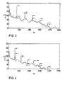
- FIGS. 3 and 4 show comparisons between the noise pressure spectrum measured in the fan outlet line for the fan with a conventional housing tongue design and with an integrated X / 4 resonator.
- the perforated cover plate 34 consists of 1 mm thick sheet metal, the holes 36 have a diameter of 3.1 mm and make up an overall opening area of 29%.
- FIG Blade frequency at 7500 rpm, that is 750 Hz and corresponding to 6000 .Upm in Fig. 4 causes.
- the solid arrows illustrate the noise level of the paddle harmonics without a resonator, that is, the resonator 30 has been replaced by a solid piece of wood.
- the dashed arrows show the noise levels of the paddle harmonics, which were measured with the X / 4 resonator 30.
- the reduction in the blade frequency is not the same in FIGS. 4 and 5, and the frequency spectrum measured at other fan speeds showed that the maximum possible reduction that can be achieved by carefully tuning the resonator for each case increases with the frequency.
- FIG. 5 in which the level of the blade frequency is plotted as a function of the fan speed.
- the solid curve A applies to the blower with the usual housing tongue shape.
- the other lines in FIG. 5 were measured with the X / 4 resonator matched to the fan frequencies, that is to say 450, 500, 550, 600, 650, 700 or 750 Hz.
- the same perforation body as for FIGS. 3 and 4 was used for the data shown in FIG.
- the damping effect is not only present at that particular frequency or within a very narrow frequency band, but extends over a fairly wide frequency range. This is important because of the practical application of the noise control method, since it shows that a significant reduction in the bucket sound can be achieved even when the resonator is not properly tuned, be it due to an initial mismatch, or a change in fan speed due to fan load, or a change in fluid temperature that corresponds to a change in the speed of noise in the fluid being moved.
- FIG. 6 shows the effect of the a / 4 resonator, which was tuned to 600 Hz over the entire noise pressure level "A", the A-weighted noise pressure level B and the second harmonic of the blade frequency C.
- the effectiveness of the X / 4 resonator with respect to the total or A-weighted noise level generally depends on the importance of the bucket sound. In the model blower used for experimental purposes, the overall noise level was reduced by 3.5 dB and the A-weighted level by 7 dB.
- FIG. 6 Another interesting result of FIG. 6 is that the second harmonic was mostly reduced at 3000 rpm, which corresponds to 600 Hz. However, the reduction is smaller than that of the blade frequency at the same resonance frequency, that is 6000 rpm (compare FIGS. 4 or 5). This shows that the impedance of the ⁇ / 4 resonator changes as a result of the flow velocity along the housing tongue.
- FIGS. 7 to 12 show a series of test data similar to that according to FIG. 5, the only difference being the perforation body 34 used to cover the resonator mouth. 7-9, the perforation rate was changed within 20% to 58% by increasing the diameter of the holes 36, that is, the total number of holes is the same in FIGS. 5 and 7 to 11. There are indications that the increase in the rate of the opening range shifts the range of maximum reduction of the blade frequency towards a lower frequency range.
- FIGS. 10 and 11 an attempt was made to change the rate of the opening area and thereby the same diameter of the holes 36 as in FIG means keeping 3.8 mm.
- some holes 36 were sealed with putty.
- Figure 10 appears to indicate the same trend as before, that is the decrease in the rate of the opening area shifts the effective area to higher frequencies.
- a further reduction in the number of holes as in FIG. 11 does not support this observation.
- FIG. 12 two perforation bodies 34 are compared, the opening area of which is the same, but in which the diameter and the approach. Number of holes 36 differ from each other. This leads to the assumption that the rate of the opening area is the size that determines the frequency range of the maximum noise reduction and not the hole diameter.
- One of the main advantages of the noise reduction method according to the invention is that the introduction of the resonator 30 requires only minor changes in the fan geometry. Therefore, as expected, the performance and flow rates for a fan 10 with or without a resonator 30 are very similar, if not practically the same. In order to empirically determine the difference in the aerodynamic performance of these two designs, the volume flow pumped through the test line 22 was measured. Table I lists the ratio of the volume flows with and without the X / 4 resonator 30 against the fan speed and the results show that the volume flow decreases by an average of 0.6%.
- the resonance frequency changes, and therefore a reduction in the blade frequency can be achieved at other fan speeds.
- the maximum possible reduction changes with the frequency, which shows that there is an optimal impedance of the resonator 30 as a whole, which causes maximum attenuation.
- the overall impedance of resonator 30 appears to be very sensitive to changes in flow velocity at resonator mouth 34, and this helps explain why the amount of noise reduction achieved by properly tuning the resonator for a given fan speed will vary with frequency, or rather the fan speed changes.
- Trials with different cover plates 34 at the resonator mouth have also shown that this optimal impedance can be generated at different frequencies by simply changing the perforation rate at the resonator mouth 34.
- a ⁇ / 4 resonator can still be used if the length of the resonator is changed in proportion to the fan speed by displacing a piston body in the resonator, and in a somewhat modified version of the preferred embodiment of the invention, therefore Piston body 32 is coupled to the impeller speed via any known suitable servomechanism.
- FIGS. 13 to 15 Three different versions of a further preferred embodiment of the invention are shown schematically in FIGS. 13 to 15.
- a centrifugal compressor 100 in the housing 112 of which an impeller 116 is accommodated, is equipped with a Helmholtz resonator 130 instead of an X / 4 resonator.
- the Helmholtz resonator 130 consists of a front wall 140, which runs essentially tangentially to the housing 112, but can follow the spiral shape of the housing in the vicinity of the housing tongue 120.
- Its rear wall consists of a main section 132 which is essentially parallel to the front wall 140 and whose lower part ends behind the housing tongue 120 at an articulation point 136.
- the end part 138 of the rear wall 132 is articulated under the articulation point 136 and is therefore freely adjustable within the resonance cavity 142 above the blower outlet 122.
- the resonance cavity 142 is in turn covered at the housing tongue end by means of a perforated cover 134.
- the Helmholtz resonator 230 is curved so that it essentially corresponds to the spiral shape of the housing 212 of the blower 200.
- a resonance cavity 242 covered by a perforated body 234 at the mouth of the resonator 230.
- the front wall 240 of the resonator abuts the housing 212, while its rear wall 232 is flexible and resilient enough to be movable in the resonance cavity 242 at its lower edge. In this way, the volume and thus the resonance frequency of the Helmholtz resonator can in turn be adjusted to changes in the fan speed and the blade frequency.
- FIG. 15 Another design of a Helmholtz resonator is shown in FIG. 15.
- the Helmholtz resonator 330 is again curved so that its front wall 340 abuts and corresponds to the spiral housing 312.
- the mouth of the resonator 330 is in the vicinity of the housing tongue 320 of the impeller 316 and the housing 312 and is covered with a perforated metal sheet 334.
- the volume of the resonant cavity 342 above the fan outlet 322 is again variable, since the rear wall 332 is either articulated to the top wall 338 at 336 or, if rigidly attached at 338, is flexible enough to tune the resonator to achieve maximum blade frequency noise reduction 330 to allow.
- FIG. 16 shows a schematic cross section through an axial fan 400, an a / 4 resonator 430 being arranged in guide vanes 420 within the fan housing 410 and behind the axial rotor 416.
- a piston 432 within the vane. 420 allows the ⁇ / 4 resonator 430 to be tuned to variable fan speeds as previously described.
- Figure 17 which illustrates a front view of axial fan 400 along lines 17-17 of Figure 16, shows perforated cover 434 at the front end of vane 420 which forms the mouth of X / 4 resonator 430.
- the piston 432 can again be coupled directly to the fan speed via any servo control means, which ensures its automatic tuning to the correct resonance frequency for maximum efficiency under variable load conditions.
Abstract
Description
Die Erfindung betrifft die Konstruktion und Arbeitsweise von Turbo-Arbeitsmaschinen, z.B. Pumpen, Gebläsen, Kompressoren, Turbinen u.dgl., bei denen Fluid durch eine in dieses eingetauchte und auf es einwirkende sich bewegende Fläche beschleunigt wird. Insbesondere bezieht sich die Erfindung auf Turbo-Arbeitsmaschinen, bei denen die Erzeugung unerwünschter Druckimpulse verringert oder aufgehoben ist. Solche Druckimpulse entstehen, wenn die sich bewegende Fläche oder die Flächen sich nahe an feststehenden Flächen auf oder innerhalb der Vorrichtung vorbeibewegen. Die unerwünschten Druckimpulse steigern den Leistungsbedarf der Vorrichtung zum Transport des Fluids beträchtlich. Durch Anordnung eines in geeigneter Weise abgestimmten akustischen Resonators an oder nahe der Zone der Vorrichtung in der die Wechselwirkung der bewegten und der feststehenden Fläche auftritt, lassen sich die unerwünschten Druckimpulse in dieser Zone vernichte, wodurch der Wirkungsgrad der Vorrichtung erhöht wird.The invention relates to the construction and operation of turbo-working machines, for example pumps, blowers, compressors, turbines and the like, in which fluid is accelerated by a moving surface immersed in it and acting on it. In particular, the invention relates to turbo machines in which the generation of undesired pressure pulses is reduced or eliminated. Such pressure pulses arise when the moving surface or surfaces move close to fixed surfaces on or within the device. The undesired pressure pulses considerably increase the power requirement of the device for transporting the fluid. By arranging a suitably tuned acoustic resonator on or near the zone of the device in which the interaction of the moving and the fixed surface occurs, the undesired pressure pulses in this zone can be destroyed, whereby the Efficiency of the device is increased.
Auf der Erzeugung von unerwünschten Druckimpulsen beruhende überschußenergie ist bei Turbo-Arbeitsmaschinen im allgemeinen als Geräusch bekannt. Die Hauptkomponente des Geräuschspektrums bei Axial- oder Radialströmungsmaschinen enthält aerodynamisch oder hydrodynamisch erzeugte Geräusche. Dagegen spielen mechanische Geräuschquellen, z.B. Lager, Antriebe oder Transmissionen nur eine untergeordnete Rolle. Der aerodynamisch oder hydrodynamisch erzeugte Schall läßt sich in zwei Anteile aufspalten, und zwar die Schaufeltonfrequenz und das Rauschen. Die Schaufeltonfrequenz wird durch die Wechselwirkung zwischen dem stationären Maschinengehäuse und dem das Laufrad mit hoher Geschwindigkeit verlassenden Fluid hervorgerufen. Die Hauptquelle der durch solche Wechselwirkungen entstehenden Schwankungen der Fluidgeschwindigkeit befindet sich an der den rotierenden Laufradschaufeln nächst gelegenen Gehäusezunge. Bei Radial-Turbo-Arbeitsmaschinen mit beschaufelten Diffusoren sind die stationären Leitschaufeln hinter dem Laufrad die akustische Hauptquelle für die Schaufeltonfrequenz. Die feststehenden Leitschaufeln werden in dieser Anmeldung als Gehäusezungen bezeichnet. Das Spektrum der Schaufeltonfrequenz ist diskret. Es weist hohe Amplitudenspitzen bei der Schaufelfrequenz auf, die das Produkt aus Drehzahl und Schaufelanzahl ist. Zusätzliche akustische Energiespitzen treten bei Harmonischen der Schaufelfrequenz auf.Excess energy based on the generation of unwanted pressure pulses is generally known as noise in turbo machines. The main component of the noise spectrum in axial or radial flow machines contains aerodynamically or hydrodynamically generated noise. In contrast, mechanical noise sources, such as bearings, drives or transmissions, play only a subordinate role. The aerodynamically or hydrodynamically generated sound can be split into two parts, namely the blade tone frequency and the noise. The blade tone frequency is caused by the interaction between the stationary machine housing and the fluid leaving the impeller at high speed. The main source of such interactions resulting from fluctuations in the F luidgeschwindigkeit at the rotating L aufradschaufeln nearest housing tongue. In radial turbo machines with bladed diffusers, the stationary guide vanes behind the impeller are the main acoustic source for the buzzer tone frequency. In this application, the fixed guide vanes are referred to as housing tongues. The spectrum of the bucket tone frequency is discrete. It has high amplitude peaks at the blade frequency, which is the product of the speed and number of blades. Additional acoustic energy peaks occur at harmonics of the blade frequency.
Die zufällige Geräuschkomponente des hörbaren Spektrums entsteht durch turbulente Strömung in der Nähe des Laufrades und des stationären Gehäuses. Ein weiterer Beitrag kommt von der Wirbelablösung an den Hinterkanten der Laufradschaufeln.The random noise component of the audible spectrum arises from turbulent flow in the vicinity of the impeller and the stationary housing. Another contribution comes from the vortex separation at the rear edges of the impeller blades.
Eine Amplitudenverringerung der Schaufeltonfrequenz ist bei Turbo-Arbeitsmaschinen besonders wichtig, weil herkömmliche Geräuschminderungsvorrichtungen einen beträchtlichen Energieverlust mit sich bringen und weil tonhaltige Geräuschkomponenten für das menschliche Ohr viel unangenehmer sind als Geräusche mit einem breiten Frequenzsprektrum. Es sind viele Versuche gemacht worden, um die Geräuschabgabe bei Zentrifugalgebläsen zu verringern. Die grundlegenden physikalischen Prinzipien dieser Versuche sind für die verschiedenen Arten von Radial-Turbo-Maschinen, z.B. Gebläsen, Pumpen, Kompressoren, Turbinen u.dgl. im wesentlichen gleich. Es ist z.B. bekannt, den Abstand zwischen dem Laufrad und der Gehäusezünge zu vergrößern, um hierdurch die Tonintensität zu verringern. Das am häufigsten benutzte Verfahren erfordert jedoch ein kostspielig vergrößertes Gebläsegehäuse und ist daher auf Anwendungsfälle begrenzt, bei denen keine Platzbeschränkungen vorhanden sind.A reduction in the amplitude of the blade tone frequency is particularly important in turbomachinery because conventional noise reduction devices involve a considerable loss of energy and because sound components containing sound are much more unpleasant for the human ear than noise with a wide frequency spectrum. Many attempts have been made to reduce the noise output from centrifugal fans. The basic physical principles of these experiments are for the different types of radial turbo machines, e.g. Blowers, pumps, compressors, turbines and the like. essentially the same. It is e.g. known to increase the distance between the impeller and the housing tongues, thereby reducing the sound intensity. However, the most commonly used method requires an expensive enlarged fan housing and is therefore limited to applications where there is no space constraint.
Außerdem ist es bekannt, den Krümmungsradius der Gehäusezunge zu vergrößern, um den Anteil der Schaufeltonfrequenz des Geräuschspektrumszu_verringern. Die sich aus dieser Vergrößerung des Radius ergebende Verringerung des Schaufelfrequenz-Geräuschpegels ist jedoch für die meisten Laufraddrehzahlen auf etwa 3 - 5 dB beschränkt.It is also known to increase the radius of curvature of the housing tongue in order to reduce the share of the blade tone frequency of the noise spectrum. However, the reduction in blade frequency noise level resulting from this increase in radius is limited to about 3-5 dB for most impeller speeds.
Ferner ist es bekannt, den Neigungswinkel zwischen den Laufradschaufeln und der Gehäusezunge zu verändern, um eine Tonintensitätsverringerung in der Größenordnung von 0 - 16 dB in Abhängigkeit von dem Gehäusezungenabstand zu erhalten. Schrägstehende Schaufeln lassen sich jedoch schwierig wirtschaftlich herstellen und eine schräge Gehäusezunge erfordert eine komplizierte Geometrie der Gebläseauslaßleitung, die Strömungsverluste nach sich zieht. Aus diesem Grunde haben frühere Versuche sich als nicht sehr praktisch, sowohl hinsichtlich der Gestaltung als auch der Wirkungsweise gezeigt.It is also known to change the angle of inclination between the impeller blades and the housing tongue in order to obtain a sound intensity reduction of the order of 0-16 dB depending on the housing tongue spacing. However, inclined blades are difficult to produce economically and an inclined housing tongue requires a complicated geometry Fan outlet line, which results in flow losses. For this reason, previous attempts have proven to be not very practical, both in terms of design and mode of operation.
Bei kleinen Gebläsen, bei denen die beiden Hälften eines Doppeleinlaßgebläses getrennt hergestellt und nachträglich zusammengebaut werden, wird eine Staffelung der Schaufeln von Doppeleinlaß- oder Doppelreihenlaufrädern manchmal zur Verringerung der Tonintensität herangezogen. Bei großenzusammengeschweißten Gebläseeinheiten verursacht diese Art der asymmetrischen Konstruktion allerdingsthermische Spannungen und Verformungen in der Rückplatte des Laufrades.In the case of small fans, in which the two halves of a double inlet fan are manufactured separately and subsequently assembled, a staggering of the blades of double inlet or double row impellers is sometimes used to reduce the sound intensity. For large welded together blower units this type caused by the asymmetrical construction Allerding s thermal stresses and deformations in the back plate of the impeller.
Die Einführung von übergangsgittern an der vorderen und hinteren Kante des Laufrades verringert nicht nur die Tonintensität, sondern auch den auf zufälligen Schwankungen beruhenden Teil des Spektrums. Es ergibt sich jedoch durch das Vorhandensein der Gitter ein Druckabfall, der eine beträchtliche Senkung der Gebläseleistung zur Folge hat.The introduction of transition grids on the front and rear edges of the impeller not only reduces the intensity of the sound, but also the part of the spectrum based on random fluctuations. However, there is a pressure drop due to the presence of the grilles, which results in a significant reduction in the blower output.
Durch unregelmäßige Anordnung der Schaufeln um die Nabe läßt sich das der Schaufelfrequenz zugeordnete Geräuschspektrum verbreitern. Obwohl dies aus einer subjektiven Einschätzung des Geräusches wünschenswert ist, wird durch diese Gestaltung die von dem Gebläse insgesamt erzeugte akustische Energie nicht verringert.The noise spectrum assigned to the blade frequency can be broadened by irregularly arranging the blades around the hub. Although this is desirable from a subjective assessment of the noise, this design does not reduce the overall acoustic energy generated by the fan.
Die Anbringung eines Keilriemens um das Laufrad verringert die Tonintensität in ähnlicher Weise wie die schräge Gestaltung der Gehäusezunge. Der das Laufrad umgebende dreieckige Riemen verursacht jedoch Reibungsverluste und senkt die Gebläseleistung.Attaching a K eilriemens around the impeller reduces the sound intensity in a manner similar to the oblique design of the housing tongue. However, the triangular belt surrounding the impeller causes friction losses and lowers the blower output.
Wenn ein herkömmliches Spiralgehäuse durch ein rechteckiges Gehäuse ersetzt und die Gehäusezunge vollständig weggelassen wird, ergibt sich eine Verringerung der Tonintensität. Aufgrund der ungenügenden Strömungsführung verschlechtert diese Konstruktion aber den aerodynamischen Wirkungsgrad des Gebläses.When a conventional volute casing replaced by a rectangular housing and the G ehäusezunge is completely omitted, this results in a reduction in the sound intensity. Due to the insufficient flow guidance, this construction deteriorates the aerodynamic efficiency of the fan.
Die Anbringung einer akustischen Auskleidung des Inneren des Gebläsegehäuses reduziert sowohl die Tonintensität als auch zufälliges Geräusch wirksam. Dieses Vorgehen hat jedoch den gleichen Nachteil wie herkömmliche absorptionsfähige Dämpfungsmittel. Nach einer gewissen Betriebszeit wird das akustische Material häufig von der Strömung weggerissen. Wenn im übrigen mit Flüssigkeit oder Feststoffen beladene Medien gefördert werden, wird die proröse Oberfläche der Auskleidung schließlich zugesetzt.The application of an acoustic lining to the interior of the blower housing effectively reduces both the intensity of the sound and random noise. However, this approach has the same disadvantage as conventional absorbent damping agents. After a certain period of operation, the acoustic material is often torn away by the flow. Finally, if media loaded with liquid or solids are conveyed, the pro-surface of the lining is added.
Auch ist eine Fehlanpassung zwischen der akustischen Impedanz des Gebläse- und Leitungssystems z.B. durch Verstellung der Länge der Gebläseauslaßleitung mit dem Zweck einer beträchtlichen Verringerung der in die Einlaßleitung abgegebenen Schaufeltonfrequenz bekannt. Dieses Vorgehen ist jedoch auf ein vorhandenes Gebläse nicht ohne weiteres anwendbar, weil der Einfluß irgendwelcher Abwandlungen, z.B. des Gebläseeinlasses,auch von der akustischen Impedanz des vorhandenen Leitungssystems an dem Gebläseauslaß abhängt.There is also a mismatch between the acoustic impedance of the blower and duct system e.g. by adjusting the length of the fan outlet line for the purpose of significantly reducing the blade tone frequency emitted into the inlet line. However, this approach is not readily applicable to an existing fan because the influence of any modifications, e.g. of the blower inlet, also depends on the acoustic impedance of the existing pipe system at the blower outlet.
Schließlich beschreibt US-PS 2 160 666 (McMahon) ein "Luftkissen" hinter der Gehäusezunge als Mittel zur Geräuschminderung. McMahon offenbart jedoch nicht,daß eine maximale Geräuschverminderung durch Abstimmung des Hohlraumes auf die Schaufeltonfrequenz und/oder durch geeignete Wahl der perforierten Abdeckung der Resonatormündung erzielbar ist.Finally, US Pat. No. 2,160,666 (McMahon) describes an "air cushion" behind the housing tongue as a means of reducing noise. McMahon does not, however, disclose that one maximum noise reduction can be achieved by tuning the cavity to the blade tone frequency and / or by suitable choice of the perforated cover of the resonator mouth.
Alle vorstehend erwähnten Maßnahmen basieren darauf, daß es bekannt ist, daß die Erzeugung des Tones im Innern eines konzentrierten Bereiches um die Gehäusezunge des Gebläsegehäuses stattfindet. Diese Erscheinung macht die Änderung des Tonerzeugungsmechanismus direkt an der Quelle zu einer aussichtsreichen Möglichkeit. Der Ton wird durch die Wechselwirkung des das Laufrad verlassenden Luftstromes mit dem die Gehäusezunge aufweisenden asymmetrischen Teil des Gebläsegehäuses hervorgerufen. Es ist bekannt, daß diese Tonerzeugung auf Änderungen der Geometrie der Gehäusezunge oder des Laufrades extrem empfindlich reagiert.All of the above-mentioned measures are based on the fact that it is known that the generation of the sound takes place in the interior of a concentrated area around the housing tongue of the blower housing. This phenomenon makes changing the sound generation mechanism directly at the source a promising option. The sound is caused by the interaction of the air flow leaving the impeller with the asymmetrical part of the fan housing which has the housing tongue. It is known that this sound generation is extremely sensitive to changes in the geometry of the housing tongue or the impeller.
Die Erfindung verhindert die Notwendigkeit der Änderung der Geometrie des Gebläses und vermeidet daher mechani- sche Beschränkungen, Schwierigkeiten und Wirkungsgradverringerungen. Das Prinzip der Erfindung besteht in der Verminderung der Tonintensität durch Anbringung eines a/4- oder Helmholtz-Resonators derart, daß die Mündung des Resonators die Gehäusezunge des Zentrifugalgebläses oder Kompressors bildet. Wenn der Resonator auf die Schaufelfrequenz oder ihre Harmonischen abgestimmt ist, werden die von der Strömung in der Gehäusezungenzone bei dieser Frequenz erzeugten Drücke wesentlich verringert. Für die Hinzufügung des Resonators wird nicht wesentlich mehr Platz benötigt. Die Geometrie der Gehäusezunge und des Gebläsegehäuses bleiben gleich.The invention avoids the need for the change of the geometry of the fan and thus avoids mechanical limitations, difficulties, and efficiency decreases. The principle of the invention is to reduce the sound intensity by attaching an a / 4 or Helmholtz resonator in such a way that the mouth of the resonator forms the housing tongue of the centrifugal fan or compressor. If the resonator is tuned to the blade frequency or its harmonics, the pressures generated by the flow in the body tongue zone at that frequency are significantly reduced. Not much more space is required to add the resonator. The geometry of the housing tongue and the fan housing remain the same.
Aufgabe der Erfindung ist die Verringerung des Pegels der Schaufeltonfrequenz bei Turbo-Arbeitsmaschinen ohne negative Beeinflussung der Kennlinie, des Wirkungsgrades oder der Größe der Vorrichtungen. In Verbindung mit und teilweise als Ergebnis eines niedrigeren Pegels der Schaufeltonfrequenz wird eine Gesamtverminderung des Geräuschpegels erreicht, insbesondere in bezug auf solche Töne, die für das menschliche Ohr besonders störend sind. Ein Gebläsesystem, bei dem die Erfindung angewendet wird, hat eine höhere Gesamtleistung als ein ähnliches Gebläsesystem mit .üblichen Dämpfern oder dergleichen.The object of the invention is to reduce the level of the bucket tone frequency in turbo-working machines without adversely affecting the characteristic curve, the efficiency or the size of the devices. In conjunction with, and in part as a result of, a lower level of the bucket tone frequency, an overall reduction in noise level is achieved, particularly with respect to those tones that are particularly disturbing to the human ear. A blower system to which the invention is applied has a higher overall performance than a similar blower system with conventional dampers or the like.
Diese Aufgaben werden dadurch gelöst, daß die Mündung eines akustischen Resonators an oder nahe dem Bereich der Vorrichtung angeordnet wird, an dem die Wechselwirkung zwischen bewegten und feststehenden Flächenteilen zur Erzeugung der unerwünschten Druckimpulse auftritt. Durch geeignete Abstimmung des Resonators können sehr unerwünschte Druckimpulse in dieser Zone durch die Druckimpulse vernichtet werden, die an der Mündung des Resonators entstehen. Konstruktionsmäßig werden die hauptsächlichen Quellregionen des Schaufeltons in dem Gehäuse als Resonatoren ausgebildet. Diese Resonatoren werden auf die Schaufelfrequenz der Vorrichtung oder ihrer Harmonischen abgestimmt. Hierdurch können die von dem das Laufrad oder die Gebläseschaufeln verlassenden Strom erzeugten Druckschwankungen direkt an ihrer Quelle vernichtet oder verringert werden. Die Hauptquellen für den Schaufelton sind die Gehäusezungen bei schaufellosen Diffusoren und die Leitschaufeln bei Vorrichtungen mit beschaufelten Diffusoren. Im Rahmen dieser Anmeldung werden diese beiden Quellen als "Gehäusezungen" bezeichnet, weil sie beide in das Innere des Maschinengehäuses vorstehen.These objects are achieved in that the mouth of an acoustic resonator is arranged at or near the area of the device at which the interaction between moving and stationary surface parts occurs in order to generate the undesired pressure pulses. By suitable tuning of the resonator, very undesirable pressure pulses in this zone can be destroyed by the pressure pulses that arise at the mouth of the resonator. In terms of construction, the main source regions of the bucket sound are formed in the housing as resonators. These resonators are tuned to the blade frequency of the device or its harmonics. As a result, the pressure fluctuations generated by the current leaving the impeller or the fan blades can be destroyed or reduced directly at their source will. The main sources for the blade sound are the housing tongues in the case of bladeless diffusers and the guide blades in devices with bladed diffusers. In the context of this application, these two sources are referred to as "housing tongues" because they both protrude into the interior of the machine housing.
Der Grundgedanke der Geräuschminderung gemäß der Erfindung ist auf Lüfter, Gebläse, Pumpen, Turbinen und Kompressoren in Radial- oder Axialbauweise anwendbar. Versuche mit Zentrifugalgebläsen haben gezeigt, daß durch Anbringung eines Resonators oder mehrerer Resonatoren an oder in der Gehäusezunge der Geräuschpegel bei der Schaufelfrequenz oder ihren Harmonischen sehr effektiv verringert werden kann. Experimentelle Senkungen bis zu 28 dB im Höhrbereich bei der Schaufelfrequenz wurden erzielt.The basic idea of noise reduction according to the invention is applicable to fans, blowers, pumps, turbines and compressors in radial or axial construction. Experiments with centrifugal fans have shown that by attaching one or more resonators to or in the housing tongue, the noise level at the blade frequency or its harmonics can be reduced very effectively. Experimental reductions of up to 28 dB in the hearing range at the blade frequency were achieved.
Einer der Hauptvorteile der Erfindung besteht darin, daß sie keinen Eingriff in die Strömungsgeometrie und das optimale Strömungsbild erfordert. Die Geometrie des Gehäuseinnenraumes muß nicht geändert werden, so daß die mechanische Kennlinie und der Wirkungsgrad der Vorrichtung durch das Vorhandensein der Resonatoren an der Gehäusezunge nicht nachteilig beeinflußt werden. Nur die innere Geometrie des Resonators selbst muß veränderlich sein, wenn abstimmbare Resonatoren gewünscht werden.One of the main advantages of the invention is that it does not require any intervention in the flow geometry and the optimal flow pattern. The geometry of the housing interior does not have to be changed, so that the mechanical characteristic and the efficiency of the device are not adversely affected by the presence of the resonators on the housing tongue. Only the internal geometry of the resonator itself has to be changeable if tunable resonators are desired.
Die Abstimmung auf verschiedene Frequenzen ist zum Beispiel durch Änderung des Hohlraumvolumens mittels wenigstens einer bewegbaren Seiten- oder Rückwand möglich. So kann der Resonator als Helmholtz-Resonator ausgebildet sein, dessen Resonanzfrequenz vom Volumen des Hohlraumes abhängt oder er kann ein A/4-Resonator sein, dessen Resonanzfrequenz wesentlich von der Tiefe des Hohlraumes beeinflußt wird.The tuning to different frequencies is possible, for example, by changing the cavity volume by means of at least one movable side or rear wall. The resonator can be designed as a Helmholtz resonator, the resonance frequency of which depends on the volume of the cavity, or it can be an A / 4 resonator, the resonance frequency of which is significantly influenced by the depth of the cavity.
Da die Grundfrequenz des Schaufeltons der Drehzahl des Laufrades direkt proportional ist, kann bei einer Ausführungsform der Erfindung eine auf die Drehzahl des Laufrades ansprechende Steuereinrichtung vorgesehen sein, die das Volumen bzw. die Tiefe des Hohlraumes als direkte Funktion der Drehzahl des Laufrades ändert. Dadurch wird erreicht, daß der Resonator immer auf die besondere Frequenz "abgestimmt" ist, die den Hauptanteil des Geräuschspektrums der Maschine bildet.Since the basic frequency of the blade sound is directly proportional to the speed of the impeller, in one embodiment of the invention a control device responsive to the speed of the impeller can be provided, which changes the volume or the depth of the cavity as a direct function of the speed of the impeller. This ensures that the resonator is always "tuned" to the particular frequency that forms the main part of the noise spectrum of the machine.
Bei einer anderen Ausführungsform der Erfindung sind mehrere Resonatoren nebeneinander angeordnet, wobei jeder Resonator auf eine andere Frequenz abgestimmt ist. Zum Beispiel können der eine Resonator auf die Frequenz der Grundschwingung und die anderen Resonatoren auf Harmonische der Grundschwingungsfrequenz abgestimmt sein.In another embodiment of the invention, a plurality of resonators are arranged next to one another, each resonator being tuned to a different frequency. For example, one resonator can be tuned to the frequency of the fundamental oscillation and the other resonators can be tuned to harmonics of the fundamental oscillation frequency.
Es zeigt:
- Fig. 1 einen schematischen Querschnitt eines Zentrifugalgebläses mit einem an der Gehäusezunge angeordneten λ/4-Resonator,
- Fig. 2 eine vergrößerte Ansicht der Gehäusezunge mit einem λ/4-Resonator zur Veranschaulichung von Einzelheiten einer Ausführungsform der Resonatormündunq,
- Fig. 3 eine graphische Darstellung der Geräuschminderung, die mit dem Resonator erzielbar ist, der abgestimmt wurde, um eine maximale Verringerung der Schaufelfrequenz bie 7500 Upm, d.h. 750 Hz zu vermitteln,
- Fig. 4 eine ähnliche graphische Darstellung, wobei der Resonator abgestimmt ist, um eine maximale Verringerung der Schaufelfrequenz bei 6000 Upm, das heißt 600 Hz hervorzubringen,
- Fig. 5 ein Diagramm des Niveaus der Schaufelfrequenz als Funktion der Gebläsedrehzahl,
- Fig. 6 die Wirkung des auf 600 Hz abgestimmten λ/4-Resonators auf das gesamte Geräuschdruckniveau, das A-gewichtete Geräuschdruckniveau und die zweite H.armonische der Schaufelfrequenz,
- Fig. 7
bis 12 eine Reihe von Versuchsdaten ähnlich denen gemäß Figur 5, jedoch mit dem Unterschied, daß die Resonatormündung mit einer perforierten Abdeckung versehen ist. Figur 7 zeigt zum Beispiel das Niveau der Schaufelfrequenz in bezug auf die Gebläsedrehzahl für verschiedene Resonatorzeiteinstellungen, wobei die Resonatormündung mit einer 20 % perforierten Abdeckung versehen ist, die mehrere Löcher mit 2,6 mm Durchmesser aufweist. Für dasDiagramm nach Figur 8 wurde eine Resonatormündung mit 42 % Öffnungsbereich verwendet, der ausLöchern von 3,8 mm Durchmesser besteht, während gemäß Figur 9 die perforierte Resonatorabdeckung 58 % Öffnungsbereich mit einzelnen Lochgrößen von 4,4 mm Durchmesser aufweist. In jedem Falle war die Gesamtanzahl der Löcher in dem für die Figuren 7 bis 9 verwendeten Perforierungskörper konstant, Figuren 10 und 11 die Wirkung von Änderungen der Rate des öffnungsbereiches in dem Perforierungskörper bei Aufrechterhaltung eines konstanten Lochdurchmessersvon 3,8 mm.Gemäß Figur 10 waren 5 von 43 Löchern geschlossen, während Figur 11 die Schaufeltonverminderung für den gleichen Perforierungskörper mit 16 geschlossenen von 43 Löchern zeigt,Figur 12 die Schaufeltonverminderung als Funktion der Gebläsedrehzahl für zwei Perforierungskörper der gleichen Rate des Öffnungsbereiches, jedoch mit verschiedenen Durchmessern und Anzahlen von Löchern,- Fig. 13,14,15 Querschnittsansichten von Radialgebläsen mit verschiedenen Ausführungsformen eines abstimmbaren Resonators an der Gehäusezunge,
- Fig. 16 einen schematischen Querschnitt eines Axialgebläses mit einem abstimmbaren A/4-Resonator in einer Leitschaufel hinter den Gebläseschaufeln, und
- Fig. 17 eine Ansicht längs der Schnittlinien A-A in Figur 16.
- 1 shows a schematic cross section of a centrifugal fan with a λ / 4 resonator arranged on the housing tongue,
- 2 is an enlarged view of the housing tongue with a λ / 4 resonator to illustrate details of an embodiment of the resonator mouth,
- 3 is a graphical representation of the noise reduction achievable with the resonator that has been tuned to provide a maximum reduction in blade frequency at 7500 rpm, ie 750 Hz.
- 4 is a similar graphical illustration with the resonator tuned to produce a maximum reduction in blade frequency at 6000 rpm, i.e. 600 Hz.
- 5 shows a diagram of the level of the blade frequency as a function of the fan speed,
- Fig. 6 shows the effect of the tuned to 600 Hz λ / 4-resonator on the entire sound pressure level, the A-weighted sound pressure level and the second H .armonische the blade frequency,
- 7 to 12 show a series of test data similar to that according to FIG. 5, but with the difference that the resonator mouth is provided with a perforated cover. For example, FIG. 7 shows the level of the blade frequency in relation to the fan speed for various resonator time settings, the resonator mouth being provided with a 20% perforated cover which has a plurality of holes with a diameter of 2.6 mm. For the diagram according to FIG. 8, a resonator mouth with 42% opening area was used, which consists of holes with a diameter of 3.8 mm, while according to FIG. 9 the perforated resonator cover has 58% opening area with individual hole sizes with a diameter of 4.4 mm. In any case, the total number of holes in the perforation body used for FIGS. 7 to 9 was constant,
- FIGS. 10 and 11 show the effect of changes in the rate of the opening area in the perforation body while maintaining a constant hole diameter of 3.8 mm. According to FIG. 10, 5 of 43 holes were closed, while FIG. 11 shows the bucket tone reduction for the same perforation body with 16 closed of 43 holes,
- FIG. 12 shows the reduction in the bucket tone as a function of the fan speed for two perforation bodies with the same rate of the opening area, but with different diameters and numbers of holes,
- 13, 14, 15 cross-sectional views of radial fans with different embodiments of a tunable resonator on the housing tongue,
- 16 shows a schematic cross section of an axial blower with a tunable A / 4 resonator in a guide blade behind the blower blades, and
- 17 shows a view along the section lines AA in FIG. 16.
Figur 1 zeigt ein Zentrifugalgebläse 10,bestehend aus einem Gebläsegehäuse 12 und einem in diesem untergebrachten Schaufelrad 14. Bei der bevorzugten Ausführungsform gemäß der Erfindung, die zur Durchführung der in den Figuren 3 bis 12 graphisch veranschaulichten Versuche verwendet wurde, ist das Schaufelrad 14 mit sechs rückwärtsgekrümmten Schaufeln 17 versehen und weist einen Durchmesser von 140 mm auf. Das Gebläsegehäuse 12 ist als logarithmische Spirale mit einem sehr kleinen Abstand der Gehäusezunge zwischen dem Schaufelrad 14 und dem Gehäuse 12 in dem Gehäusezungenbereich 18 ausgebildet. Der Gehäusezungenabstand 18 beträgt nur 4,4 mm,und der Gehäusezungenradius 20 des für die Versuche benutzten Modellgebläses 10 ist nur 10 mm.FIG. 1 shows a
An der Stelle 20 der Gehäusezunge ist gemäß Figur 1 ein X/4-Resonator 30 angeordnet. Ein innerhalb des Resonators 30 kolbenartig verschiebbarer Stopfen 32 wird zur Abstimmung des Resonators für verschiedene Frequenzen benutzt.According to FIG. 1, an X / 4
Die Geräuschminderungswirkung verschiedener Gestaltungen des Resonators 30 wurde durch Anordnung eines Mikrophons in der Gebläseauslaßleitung 22 gemessen. Das Mikrophon in der Leitung war zur Verringerung des Einflusses von turbulenten Druckschwankungen auf das Mikrophon mit einem Schlitzrohr versehen worden. Die Mikrophonsignale wurden mittels eines Schmalbandfilters analysiert, das mit Hilfe einer Gleichlaufeinrichtung auf die Schaufelfrequenz oder vielfache Harmonische dieser abgestimmt werden konnte. Zur Aufnahme des Frequenzspektrums des Geräuschdrucks in der Leitung wurde ein Realzeitanalysator benutzt.The noise reduction effect of various designs of the
Figur 2 zeigt einen vergrößerten Querschnitt der Gehäusezunge mit dem Resonator 30, wobei die Mündung 34 an der Gehäusezunge als perforierte Abdeckung an dem Resonatoreingang dargestellt ist. Die perforierte Abdeckung 34 besteht aus 1 mm dickem Metallblech, das im Verlauf der Versuche für verschiedene Ausgestaltungen mit unterschiedlicher Anordnung,Größe und Anzahl der Öffnungen 36 ausgetauscht wurde. Der Querschnittsbereich des Resonators 30 ist rechteckig und seine größte Seitenabmessung entspricht der Breite des Gebläsegehäuses. Die obere Resonatorwand 38 mit einer Breite von 46,1 mm befindet sich 16,5 mm oberhalb einer unteren Resonatorwand 41 gleicher Breite.FIG. 2 shows an enlarged cross section of the housing tongue with the
Zur Abstimmung des Resonators 30 wurde die Länge des Resonators über einen beweglichen Teflonstopfen 32 verändert, der einen luftdichten Abschluß mit den Resonatorwänden bildete. Eine optimale Abstimmung, das heißt maximale Lärmverminderung bei einer gegebenen,Frequenz wurde einfach durch Beobachtung der Amplitude des Tons auf den Realzeitanalysator erhalten. Alle Geräuschmessungen wurden an nur einer Betriebsstelle des Gebläses durchgeführt, die sich auf der rechten Seite der Druckkopf-Volumenströmungscharakteristik befand, das heißt beinaheam freien Auslaß. Zur Erzielung von Bezugsdaten für Vergleichszwecke wurde der Resonator 30 bei einigen Versuchen ersetzt durch ein massives Holzstück mit dem gleichen Krümmungsradius 20 und dem gleichen Abstand vom Schaufelrad 14.To tune the
Figuren 3 und 4 zeigen Vergleiche zwischen dem Geräuschdruckspektrum, das in der Gebläseauslaßleitung für das Gebläse mit einer üblichen Gehäusezungengestaltung und mit eingebautem X/4-Resonator gemessen wurde. Die perforierte Abdeckplatte 34 besteht aus 1 mm dickem Metallblech, dessen Löcher 36 einen Durchmesser von 3,1 mm haben und insgesamt einen öffnungsbereich von 29 % ausmachen.Für das in Figur 3 gezeigte Spektrum wurde der Resonator so abgestimmt, daß er eine maximale Verringerung der Schaufelfrequenz bei 7500 Upm, das heißt 750 Hz und entsprechend 6000 .Upm in Fig. 4 hervorruft. In beiden Figuren 3 und 4 veranschaulichen die durchgezogenen Pfeile die Geräuschpegel der Schaufeltonharmonischen ohne einen Resonator, das heißt der Resonator 30 wurde durch ein massives Holzstück ersetzt. Die gestrichelten Pfeile zeigen die Geräuschpegel der Schaufeltonharmonischen, die mit dem X/4-Resonator 30 gemessen wurden.FIGS. 3 and 4 show comparisons between the noise pressure spectrum measured in the fan outlet line for the fan with a conventional housing tongue design and with an integrated X / 4 resonator. The
Eine richtige Abstimmung des Resonators verringert nicht nur die Schaufelfrequenz, sondern auch ihre höheren Harmonischen. Sie kann jedoch auch zu einer Verstärkung führen, wie in Figur 4 gezeigt ist, wo die dritte Harmonische um 8 dB erhöht wurde.Correct tuning of the resonator not only reduces the blade frequency, but also its higher harmonics. However, it can also result in gain, as shown in Figure 4, where the third harmonic has been increased by 8 dB.
Die Verringerung der Schaufelfrequenz ist in den Figuren 4 und 5 ungleich,und das bei anderen Gebläsedrehzahlen gemessene Frequenzspektrum zeigte, daß die maximal mögliche Verminderung,die durch sorgfältige Abstimmung des Resonators für jeden Fall erzielbar ist, mit der Frequenz zunimmt.The reduction in the blade frequency is not the same in FIGS. 4 and 5, and the frequency spectrum measured at other fan speeds showed that the maximum possible reduction that can be achieved by carefully tuning the resonator for each case increases with the frequency.
Dieser Effekt wird in Figur 5 deutlicher, in der das Niveau der Schaufelfrequenz als Funktion der Gebläsedrehzahl aufgetragen ist. Die durchgezogene Kurve A gilt für das Gebläse mit der üblichen Gehäusezungenform. Die anderen Linien in Figur 5 wurden mit dem auf die Gebläsefrequenzen, das heißt 450, 500, 550, 600, 650,700 bzw. 750 Hz abgestimmten X/4-Resonator gemessen. Die maximal mögliche Verminderung steigt mit der Frequenz in Figur 5 an und weitere Versuche haben gezeigt, daß dies durch Verwendung eines anderen Perforationskörpers für die Resonatormündung geändert werden kann. Für die in Figur 5 gezeigten Daten wurde der gleiche Perforationskörper wie für Figuren 3 und 4 verwendet. Für eine gegebene Resonanzfrequenz ist der Dämpfungseffekt nicht nur bei dieser besonderen Frequenz oder innerhalb eines sehr schmalen Frequenzbandes vorhanden, sondern er erstreckt sich über einen recht breiten Frequenzbereich. Dies ist wichtig wegen der praktischen Anwendung der Geräuschkontrollmethode, da es zeigt, daß eine wesentliche Verminderung des Schaufeltons sogar dann erreichbar ist, wenn der Resonator nicht richtig abgestimmt ist, sei es aufgrund anfänglicher Fehlabstimmung oder aufgrund einer Änderung der Gebläsedrezahl infolge der Gebläsebelastung oder aufgrund einer Änderung der Fluidtemperatur, die einer Änderung der Geschwindigkeit des Geräusches in dem bewegten Fluid entspricht.This effect becomes clearer in FIG. 5, in which the level of the blade frequency is plotted as a function of the fan speed. The solid curve A applies to the blower with the usual housing tongue shape. The other lines in FIG. 5 were measured with the X / 4 resonator matched to the fan frequencies, that is to say 450, 500, 550, 600, 650, 700 or 750 Hz. The maximum possible reduction increases with the frequency in FIG. 5 and further tests have shown that this can be changed by using a different perforation body for the resonator mouth. The same perforation body as for FIGS. 3 and 4 was used for the data shown in FIG. For a given resonance frequency, the damping effect is not only present at that particular frequency or within a very narrow frequency band, but extends over a fairly wide frequency range. This is important because of the practical application of the noise control method, since it shows that a significant reduction in the bucket sound can be achieved even when the resonator is not properly tuned, be it due to an initial mismatch, or a change in fan speed due to fan load, or a change in fluid temperature that corresponds to a change in the speed of noise in the fluid being moved.
Figur 6 zeigt die Wirkung des a/4-Resonators, der auf 600 Hz über das gesamte Geräuschdruckniveau "A",das A-gewichtete Geräuschdruckniveau B und die zweite Harmonische der Schaufelfrequenz C abgestimmt wurde. Die Wirksamkeit des X/4-Resonators in bezug auf die gesamten oder A-gewichteten Geräuschpegel hängt im allgemeinen von der jeweiligen Bedeutung des Schaufeltons ab. Bei dem für Versuchszwecke benutzten Modellgebläse war das gesamte Geräuschdruckniveau um 3,5 dB verringert und das A-gewichtete Niveau um 7 dB.FIG. 6 shows the effect of the a / 4 resonator, which was tuned to 600 Hz over the entire noise pressure level "A", the A-weighted noise pressure level B and the second harmonic of the blade frequency C. The effectiveness of the X / 4 resonator with respect to the total or A-weighted noise level generally depends on the importance of the bucket sound. In the model blower used for experimental purposes, the overall noise level was reduced by 3.5 dB and the A-weighted level by 7 dB.
Ein anderes interessantes Ergebnis der Figur 6 ist,daß die zweite Harmonische meistens bei 3000 Upm, die 600 Hz entsprechen, verringert wurde. Die Verminderung ist jedoch kleiner als die der Schaufelfrequenz bei gleicher Resonanzfrequenz, das heißt 6000 Upm (vergleiche Figuren 4 oder 5). Dies zeigt, daß die Impedanz des λ/4-Resonators sich infolge der Strömungsgeschwindigkeit längs der Gehäusezunge ändert.Another interesting result of FIG. 6 is that the second harmonic was mostly reduced at 3000 rpm, which corresponds to 600 Hz. However, the reduction is smaller than that of the blade frequency at the same resonance frequency, that is 6000 rpm (compare FIGS. 4 or 5). This shows that the impedance of the λ / 4 resonator changes as a result of the flow velocity along the housing tongue.
Figuren 7 bis 12 zeigen eine Reihe von Versuchsdaten ähnlich denjenigen nach Figur 5, wobei der einzige Unterschied der zur Abdeckung der Resonatormündung verwendete Perforierungskörper 34 ist. Gemäß Fig. 7 bis 9 wurde die Perforationsrate innerhalb von 20 % bis 58 % geändert, indem der Durchmesser der Löcher 36 vergrößert wurde, das heißt die Gesamtanzahl der Löcher ist die gleiche in den Figuren 5 und 7 bis 11. Es gibt Anzeichen, daß die Zunahme der Rate des öffnungsbereiches den Bereich maximaler Verminderung der Schaufelfrequenz gegen einen niedrigeren Frequenzbereich verschiebt.FIGS. 7 to 12 show a series of test data similar to that according to FIG. 5, the only difference being the
Eine physikalische Erklärung der Dämpfungserscheinung bei der Frequenzverschiebung läßt sich auf folgende Weise entwickeln. Wenn der Durchmesser der Löcher.36 groß ist, wird die Oszillation der Luft durch die Löcher nur wenig gedämpft, weshalb die Verminderung der Tonamplitude groß ist. Es ist jedoch zu beachten, daß diese Verminderung nur über eine schmalere Bandbreite als in Figur 9 gezeigt auftritt. Wenn umgekehrt die Löcher 36 klein sind, nimmt die Dämpfungsrate des Resonators 30 zu, mit dem Ergebnis einer tieferen Verringerung der Tonamplitude, jedoch über einen breiteren Frequenzbereich als in Figur 7 gezeigt.A physical explanation of the damping phenomenon during the frequency shift can be developed in the following way. If the diameter of the holes. 36 is large, the oscillation of the air through the holes is little damped, so the reduction in the tone amplitude is large. It should be noted, however, that this reduction only occurs over a narrower bandwidth than that shown in Figure 9. Conversely, if the
In den Figuren 10 und 11 wurde versucht, die Rate des öffnungsbereiches zu verändern und dabei die gleichen Durchmesser der Löcher 36 wie in Figur 8, das heißt 3,8 mm beizubehalten. Zu diesem Zweck wurden einige Löcher 36 mit Kitt verschlossen. Figur 10 scheint den gleichen Trend wie vorher anzuzeigen, das heißt die Verminderung der Rate des Öffnungsbereiches verschiebt den wirksamen Bereich zu höheren Frequenzen. Eine weitere Reduzierung der Lochanzahl wie in Figur 11 stützt diese Beobachtung jedoch nicht.In FIGS. 10 and 11 an attempt was made to change the rate of the opening area and thereby the same diameter of the
In Figur 12 werden schließlich zwei Perforationskörper 34 verglichen, deren öffnungsbereich gleich ist, bei denen jedoch die Durchmesser und die An- . zahl der Löcher 36 voneinander abweichen. Dies führt zu der Annahme, daß die Rate des öffnungsbereiches die Größe ist, die den Frequenzbereich der maximalen Geräuschverminderung bestimmt und nicht der Lochdurchmesser.Finally, in FIG. 12 two
Einer der Hauptvorteile des Geräuschminderungsverfahrens gemäß der Erfindung besteht darin, daß die Einführung des Resonators 30 nur geringe Änderungen der Gebläsegeometrie erforderlich macht. Deshalb sind die Leistung und Strömungsraten bei einem Gebläse 10 mit oder ohne Resonator 30 erwartungsgemäß sehr ähnlich, wenn nicht praktisch gleich. Um die Differenz der aerodynamischen Leistung dieser beiden Gestaltungen empirisch zu bestimmen, wurde der durch die Testleitung 22 gepumpte Volumenstrom gemessen. In Tabelle I ist das Verhältnis der Volumenströme mit und ohne X/4-Resonator 30 gegen die Gebläsedrehzahl aufgelistet und die Ergebnisse zeigen, daß der Volumenstrom um durchschnittlich 0,6 % abnimmt.

Die vorstehenden Versuchsergebnisse zeigen, daß eine wesentliche Verringerung der von Zentrifugalgebläsen abgegebenen Schaufel.tonfrequenz durch Einbau eines λ/4-Resonators an der Gehäusezunge erreicht werden kann.The above test results show that a substantial reduction in the blade frequency emitted by centrifugal fans can be achieved by installing a λ / 4 resonator on the housing tongue.
Bei einer unveränderten Resonatorform, das heißt bei konstanter Länge und Mündungsgeometrie des Resonators 30, tritt eine maximale Dämpfung der Schaufelfrequenz bei einer Frequenz auf, bei der die Geräuschwellenlänge etwa gleich dem Vierfachen der Resonatorlänge ist. Eine Relation für die wirksame Länge des Resonators läßt sich wegen der gekrümmten Gestaltung und der das Mündungstück 34 bildenden Perforationen mit Konstruktionsparametern schwierig ausdrücken. Außerdem wirken die überströmlöcher 36 auch auf den Massezuschlag zu der effektiven Länge. Eine etwas geringere Dämpfung der Schaufelfrequenz ergibt sich innerhalb eines Frequenzbandes im Bereich der Resonanzfrequenz des Resonators. Die Breite dieses Frequenzbandes wird durch die Dämpfungsrate des Resonators bestimmt, die ihrerseits von der Größe und Anzahl der Löcher 36 in dem Mündungsstück 34 abhängt.With an unchanged resonator shape, that is to say with a constant length and mouth geometry of the
Wenn die Länge des Resonators 30 verändert wird, während die gleiche Resonatormündungsform 34 beibehalten bleibt, ändert sich die Resonanzfrequenz, und daher ist eine Verringerung der Schaufelfrequenz bei anderen Gebläsedrehzahlen erzielbar. Die maximal mögliche Verringerung ändert sich jedoch mit der Frequenz, was zeigt, daß dort eine optimale Impedanz des Resonators 30 als Gesamtheit herrscht, die eine maximale Dämpfung hervorruft. Die Gesamtimpedanz des Resonators 30 scheint sehr empfindlich auf Änderungen der Strömungsgeschwindigkeit an der Resonatormündung 34 zu reagieren.und dies hilft bei der Erklärung,warum der Betrag,der durch richtige Abstimmung des Resonators für eine gegebene Gebläsedrehzahl erzielten Geräuschverminderung sich mit der Frequenz oder besser gesagt mit der Gebläsedrehzahl ändert. Versuche mit verschiedenen Abdeckplatten 34 an der Resonatormündung haben auch gezeigt, daß diese optimale Impedanz sich bei verschiedenen Frequenzen durch einfache Änderung der Perforationsrate an der Resonatormündung 34 erzeugen läßt.If the length of the
Versuche mit den beschriebenen bevorzugten Ausführungsformen der Erfindung zeigten, daß ein X/4-Resonator an der Gehäusezunge eines Zentri- .fugalgebläses ein hochwirksames und extrem einfaches Mittel zur Verminderung des Schaufeltones ist. Dieses Verfahren kann zur Geräuschminderung sowohl bei neuen Gebläsekonstruktionen als auch bei bestehenden Anlagen benutzt werden. Da der Einsatz eines X/4-Resonators keine Änderung der Geometrie der Gehäusespirale verlangt, wird der aerodynamische Wirkungsgrad des Gebläses nicht beeinträchtigt.Experiments with the described preferred embodiments of the invention showed that an X / 4 resonator on the housing tongue of a centrifugal fan is a highly effective and extremely simple means of reducing the blade tone. This method can be used to reduce noise in both new fan designs and existing systems. Since the use of an X / 4 resonator does not require a change in the geometry of the housing spiral, the aerodynamic efficiency of the fan is not impaired.
Bei Gebläsen mit veränderlicher Drehzahl kann noch ein λ/4-Resonator benutzt werden, wenn die Länge des Resonators proportional zur Gebläsedrehzahl geändert wird, indem ein Kolbenkörper in dem Resonator verschoben wird,und bei einer etwas abgewandelten Version der bevorzugten Ausführungsform der Erfindung ist deshalb der Kolbenkörper 32 über irgendeinen bekannten geeigneten Servomechanismus mit der Laufraddrehzahl gekoppelt.For variable speed fans, a λ / 4 resonator can still be used if the length of the resonator is changed in proportion to the fan speed by displacing a piston body in the resonator, and in a somewhat modified version of the preferred embodiment of the invention, therefore
Drei verschiedene Versionen einer weiteren bevorzugten Ausführungsform der Erfindung sind schematisch in den Figuren 13 bis 15 dargestellt. In Figur 13 ist zum Beispiel ein Zentrifugalkompressor 100, in dessen Gehäuse 112 ein Laufrad 116 untergebracht ist, anstatt mit einem X/4-Resonator mit einem Helmholtzresonator 130 ausgerüstet. Der Helmholtzresonator 130 besteht aus einer Frontwand 140, die im wesentlich tangential zu dem Gehäuse 112 verläuft, jedoch der Spiralform des Gehäuses in der Nähe der Gehäusezunge 120 folgen kann. Seine Rückwand besteht aus einem Hauptabschnitt 132, der im wesentlichen parallel zur Frontwand 140 ist und dessen unterer Teil hinter der Gehäusezunge 120 an einer Gelenkstelle 136 endet. Der Endteil 138 der Rückwand 132 ist unter der Gelenkstelle 136 gelenkig beweglich und daher innerhalb des Resonanzhohlraumes 142 über dem Gebläseauslaß 122 frei verstellbar. Der Resonanzhohlraum 142 ist seinerseits an dem Gehäusezungenende mittels einer perforierten Abdeckung 134 abgedeckt. Durch Bewegung der Endklappe 138 in dem Resonanzhohlraum 142 lassen sich das Volumen und damit die Resonanzfrequenz des Helmholtz- resonators 130 ändern, um auf maximale Schaufelfrequenz- Geräuschverminderung abgestimmt zu werden.Three different versions of a further preferred embodiment of the invention are shown schematically in FIGS. 13 to 15. In FIG. 13, for example, a
In Figur 14 ist der Helmholtzresonator 230 so gekrümmt, daß er im wesentlichen der Spiralform des Gehäuses 212 des Gebläses 200 entspricht. Neben der Gehäusezunge 220 des Laufrades 216 und des Gehäuses 212 wird ein Resonanzhohlraum 242 von einem perforierten Körper 234 an der Mündung des Resonators 230 abgedeckt. Die Frontwand 240 des Resonators stößt an das Gehäuse 212 an, während seine Rückwand 232 flexibel und elastisch genug ist, um an seinem unteren Rand in dem Resonanzhohlraum 242 beweglich zu sein. Auf diese Weise sind das Volumen und damit die Resonanzfrequenz des Helmholtz-Resonators wiederum einstellbar auf Veränderungen der Gebläsedrehzahl und der Schaufelfrequenz.In FIG. 14, the
Noch eine weitere Gestaltung eines Helmholtz- resonators ist in Figur 15 dargestellt. Der Helmholtzresonator 330 ist wieder so gekrümmt, daß seine Frontwand 340 an das Spiralgehäuse 312 anliegt und diesem entspricht. Die Mündung des Resonators 330 befindet sich in der Nähe der Gehäusezunge 320 des Laufrades 316 und des Gehäuses 312 und sie ist mit einem perforierten Metallblech 334 abgedeckt. Das Volumen des Resonanzhohlraums 342 oberhalb des Gebläseauslasses 322 ist wiederum veränderlich, da die Rückwand 332 entweder bei 336 an die Oberwand 338 angelenkt oder falls sie bei 338 starr befestigt ist, flexibel genug ist, um zur Erzielung einer maximalen Schaufelfrequenz-Geräuschverminderung eine Abstimmung des Resonators 330 zu ermöglichen.Another design of a Helmholtz resonator is shown in FIG. 15. The
Obwohl die Erfindung vorwiegend mit Bezug auf die Anwendung eines A/4-oder Helmholtzresonators innerhalb von Zentrifugalgebläsen beschrieben wurde, können die gleiche Vorrichtung und das Verfahren zur Verminderung des Geräuschpegels der Schaufelfrequenz von Axialgebläsen benutzt werden. Figur 16 zeigt zum Beispiel einen schematischen Querschnitt durch ein Axialgebläse 400, wobei ein a/4-Resonator 430 in Leitschaufeln 420 innerhalb des Gebläsegehäuses 410 und hinter dem Axialrotor 416 angeordnet ist. Ein Kolben 432 innerhalb der Leitschaufel . 420 erlaubt eine Abstimmung des λ/4-Resonators 430 auf veränderliche Gebläsedrehzahlen wie vorher beschrieben.Although the invention has been described primarily with reference to the use of an A / 4 or Helmholtz resonator within centrifugal fans, the same device and method can be used be used to reduce the noise level of the blade frequency of axial fans. For example, FIG. 16 shows a schematic cross section through an
Figur 17, die eine Frontansicht des Axialgebläses 400 längs der Linien 17-17 der Figur 16 veranschaulicht, zeigt die perforierte Abdeckung 434 am vorderen Ende der Leitschaufel 420, die die Mündung des X/4-Resonators 430 bildet. Der Kolben 432 kann wieder über beliebige Servokontrollmittel direkt mit der Gebläsedrehzahl gekoppelt sein, wodurch seine automatische Abstimmung auf die richtige Resonanzfrequenz für einen maximalen Wirkungsgrad unter veränderlichen Belastungsbedingungen gewährleistet wird.Figure 17, which illustrates a front view of
Verschiedene andere Ausführungsformen und Abwandlungen sind ebenfalls aus der vorangehenden Beschreibung ersichtlich. Die Erfindung ist deshalb nicht auf die offenbarten speziellen Ausführungsformen beschränkt, sondern erstreckt sich auf jede Ausführungsform im Rahmen der anschließenden Ansprüche.Various other embodiments and modifications are also apparent from the foregoing description. The invention is therefore not limited to the specific embodiments disclosed, but extends to each embodiment within the scope of the following claims.
Claims (14)
Applications Claiming Priority (2)
| Application Number | Priority Date | Filing Date | Title |
|---|---|---|---|
| PCT/US1980/000466 WO1981003201A1 (en) | 1980-04-28 | 1980-04-28 | Noise reduction system |
| WOPCT/US80/00466 | 1980-04-28 |
Publications (2)
| Publication Number | Publication Date |
|---|---|
| EP0039459A1 true EP0039459A1 (en) | 1981-11-11 |
| EP0039459B1 EP0039459B1 (en) | 1983-10-05 |
Family
ID=22154300
Family Applications (2)
| Application Number | Title | Priority Date | Filing Date |
|---|---|---|---|
| EP19810900348 Withdrawn EP0050621A1 (en) | 1980-04-28 | 1980-04-28 | Noise reduction system |
| EP19810103122 Expired EP0039459B1 (en) | 1980-04-28 | 1981-04-25 | Silenced turbo-machine |
Family Applications Before (1)
| Application Number | Title | Priority Date | Filing Date |
|---|---|---|---|
| EP19810900348 Withdrawn EP0050621A1 (en) | 1980-04-28 | 1980-04-28 | Noise reduction system |
Country Status (3)
| Country | Link |
|---|---|
| EP (2) | EP0050621A1 (en) |
| DE (1) | DE3161106D1 (en) |
| WO (1) | WO1981003201A1 (en) |
Cited By (22)
| Publication number | Priority date | Publication date | Assignee | Title |
|---|---|---|---|---|
| FR2523658A1 (en) * | 1982-03-17 | 1983-09-23 | Deutsche Forsch Luft Raumfahrt | LOW NOISE TURBOMACHINE |
| WO1989011596A1 (en) * | 1988-05-25 | 1989-11-30 | Universitet Druzhby Narodov Imeni Patrisa Lumumby | Radial ventilator |
| EP0466983A1 (en) * | 1990-07-16 | 1992-01-22 | Crosslee Plc | Noise suppression |
| WO1992015088A1 (en) * | 1991-02-21 | 1992-09-03 | Lotus Cars Limited | Method and apparatus for attenuating acoustic vibrations in a medium |
| EP0573895A1 (en) * | 1992-06-12 | 1993-12-15 | A.G. Kühnle, Kopp & Kausch | Turbocharger with a radial compressor |
| EP0594626A1 (en) * | 1991-07-16 | 1994-05-04 | Noise Cancellation Technologies, Inc. | High efficiency fan with adaptive noise cancellation |
| EP0638728A1 (en) * | 1993-08-02 | 1995-02-15 | Foster Wheeler Energy Corporation | Rotary throat cutoff device and method for reducing centrifugal fan noise |
| EP0703368A3 (en) * | 1994-09-20 | 1998-04-01 | Hitachi, Ltd. | Fluidal machine |
| DE19818874A1 (en) * | 1998-04-28 | 1999-11-04 | Man B & W Diesel As | Reciprocating piston internal combustion engine, especially supercharged diesel engine |
| DE19818873A1 (en) * | 1998-04-28 | 1999-11-11 | Man B & W Diesel Ag | Silencer for large high-power diesel internal combustion engine |
| FR2780454A1 (en) * | 1998-06-29 | 1999-12-31 | Valeo Climatisation | Noise absorption device for a centrifuge motor-fan unit in an automobile air conditioning system |
| WO2000050302A1 (en) * | 1999-02-25 | 2000-08-31 | United Technologies Corporation | Passively driven acoustic jet controlling boundary layers |
| US6546729B2 (en) | 2000-11-25 | 2003-04-15 | Alstom (Switzerland) Ltd | Damper arrangement for reducing combustion-chamber pulsations |
| FR2856442A1 (en) * | 2003-06-19 | 2004-12-24 | Renault Sa | Centrifugal ventilation device for motor vehicle, has suction unit adjacent to opening of air outlet and extending perpendicular to direction of air flow exhaust via opening of air outlet |
| WO2005073561A1 (en) | 2004-01-30 | 2005-08-11 | Pax Scientific, Inc | Housing for a centrifugal fan, pump or turbine |
| DE102011120347A1 (en) | 2011-11-30 | 2013-06-06 | Maik Hentschel | Structured multi-layer tubular air charge line for internal combustion engine, has inner layer for thermal and sound insulation which is made of thermoplastic foam layer of variable layer thickness and formed by blow molding process |
| CN108087340A (en) * | 2016-11-21 | 2018-05-29 | 英业达科技有限公司 | Centrifugal fan structure |
| CN108506231A (en) * | 2018-03-22 | 2018-09-07 | 英业达科技有限公司 | Fan assembly |
| CN109654067A (en) * | 2017-10-12 | 2019-04-19 | 英业达科技有限公司 | Quiet fan |
| US10393384B2 (en) | 2015-06-09 | 2019-08-27 | Rolls-Royce North American Technologies Inc. | Wave rotor with canceling resonator |
| WO2022156929A1 (en) | 2021-01-21 | 2022-07-28 | Voith Patent Gmbh | Francis-type hydraulic machine |
| DE102021133907A1 (en) | 2021-12-20 | 2023-06-22 | Viessmann Climate Solutions Se | compressor device |
Families Citing this family (12)
| Publication number | Priority date | Publication date | Assignee | Title |
|---|---|---|---|---|
| IT241428Y1 (en) * | 1996-11-22 | 2001-05-09 | Casappa Spa | REDUCED PRESSURE PULSE HYDRAULIC PUMP. |
| SE0004624D0 (en) * | 2000-12-14 | 2000-12-14 | Flaekt Ab | Fluid transport system |
| DE10143686B4 (en) * | 2001-08-31 | 2016-07-21 | Volkswagen Ag | Ventilation device for internal combustion engines |
| AUPR982302A0 (en) | 2002-01-03 | 2002-01-31 | Pax Fluid Systems Inc. | A fluid flow controller |
| CN1985093A (en) | 2004-01-30 | 2007-06-20 | 百思科技公司 | Housing for a centrifugal fan, pump or turbine |
| WO2009152420A2 (en) | 2008-06-13 | 2009-12-17 | The Penn State Research Foundation | Dipole flow driven resonators for fan noise mitigation |
| US9388731B2 (en) * | 2013-03-15 | 2016-07-12 | Kohler Co. | Noise suppression system |
| US9752494B2 (en) | 2013-03-15 | 2017-09-05 | Kohler Co. | Noise suppression systems |
| DE102014206114A1 (en) | 2014-04-01 | 2015-10-01 | Mahle International Gmbh | Housing of a radial fan |
| US10473120B2 (en) | 2017-03-09 | 2019-11-12 | Denso International America, Inc. | Blower assembly having resonators and resonator assembly |
| CN110439860A (en) * | 2018-05-04 | 2019-11-12 | 宁波方太厨具有限公司 | A kind of volute structure of centrifugal blower |
| GB2606704B (en) * | 2021-04-29 | 2023-12-27 | Dyson Technology Ltd | Noise reduction for air flow devices |
Citations (10)
| Publication number | Priority date | Publication date | Assignee | Title |
|---|---|---|---|---|
| NL94357C (en) * | 1900-01-01 | |||
| NL41785C (en) * | 1900-01-01 | |||
| US2160666A (en) * | 1936-06-01 | 1939-05-30 | Gen Electric | Fan |
| US2171341A (en) * | 1936-06-01 | 1939-08-29 | Gen Electric | Fan casing |
| US2225398A (en) * | 1939-09-13 | 1940-12-17 | Clyde M Hamblin | Construction of ventilating fans |
| CH261468A (en) * | 1948-01-26 | 1949-05-15 | Oerlikon Maschf | Device for reducing the noise of centrifugal compressors and fans. |
| US3572962A (en) * | 1969-06-02 | 1971-03-30 | Canadian Patents Dev | Stator blading for noise reduction in turbomachinery |
| FR2393960A1 (en) * | 1977-06-08 | 1979-01-05 | Berry Sa | Silencing system for axial flow fan - has glass wool lined duct with resonator tubes tuned to absorb sound of different frequencies |
| GB2001135A (en) * | 1977-07-13 | 1979-01-24 | Carrier Corp | Pressure variation absorber |
| AU502370B2 (en) * | 1975-07-01 | 1979-07-26 | Louis A. Challis | Acoustic treatment for fans |
Family Cites Families (3)
| Publication number | Priority date | Publication date | Assignee | Title |
|---|---|---|---|---|
| US2403699A (en) * | 1936-12-12 | 1946-07-09 | Gen Motors Corp | Resonator silencer |
| US2514344A (en) * | 1944-07-10 | 1950-07-04 | Stromberg Carlson Co | Adjustable acoustic impedance |
| US4174020A (en) * | 1975-07-01 | 1979-11-13 | Challis Louis A | Acoustic treatment for fans |
-
1980
- 1980-04-28 EP EP19810900348 patent/EP0050621A1/en not_active Withdrawn
- 1980-04-28 WO PCT/US1980/000466 patent/WO1981003201A1/en unknown
-
1981
- 1981-04-25 EP EP19810103122 patent/EP0039459B1/en not_active Expired
- 1981-04-25 DE DE8181103122T patent/DE3161106D1/en not_active Expired
Patent Citations (10)
| Publication number | Priority date | Publication date | Assignee | Title |
|---|---|---|---|---|
| NL94357C (en) * | 1900-01-01 | |||
| NL41785C (en) * | 1900-01-01 | |||
| US2160666A (en) * | 1936-06-01 | 1939-05-30 | Gen Electric | Fan |
| US2171341A (en) * | 1936-06-01 | 1939-08-29 | Gen Electric | Fan casing |
| US2225398A (en) * | 1939-09-13 | 1940-12-17 | Clyde M Hamblin | Construction of ventilating fans |
| CH261468A (en) * | 1948-01-26 | 1949-05-15 | Oerlikon Maschf | Device for reducing the noise of centrifugal compressors and fans. |
| US3572962A (en) * | 1969-06-02 | 1971-03-30 | Canadian Patents Dev | Stator blading for noise reduction in turbomachinery |
| AU502370B2 (en) * | 1975-07-01 | 1979-07-26 | Louis A. Challis | Acoustic treatment for fans |
| FR2393960A1 (en) * | 1977-06-08 | 1979-01-05 | Berry Sa | Silencing system for axial flow fan - has glass wool lined duct with resonator tubes tuned to absorb sound of different frequencies |
| GB2001135A (en) * | 1977-07-13 | 1979-01-24 | Carrier Corp | Pressure variation absorber |
Cited By (35)
| Publication number | Priority date | Publication date | Assignee | Title |
|---|---|---|---|---|
| FR2523658A1 (en) * | 1982-03-17 | 1983-09-23 | Deutsche Forsch Luft Raumfahrt | LOW NOISE TURBOMACHINE |
| WO1989011596A1 (en) * | 1988-05-25 | 1989-11-30 | Universitet Druzhby Narodov Imeni Patrisa Lumumby | Radial ventilator |
| EP0466983A1 (en) * | 1990-07-16 | 1992-01-22 | Crosslee Plc | Noise suppression |
| WO1992015088A1 (en) * | 1991-02-21 | 1992-09-03 | Lotus Cars Limited | Method and apparatus for attenuating acoustic vibrations in a medium |
| EP0594626A1 (en) * | 1991-07-16 | 1994-05-04 | Noise Cancellation Technologies, Inc. | High efficiency fan with adaptive noise cancellation |
| EP0594626A4 (en) * | 1991-07-16 | 1995-08-23 | Noise Cancellation Tech | High efficiency fan with adaptive noise cancellation |
| EP0573895A1 (en) * | 1992-06-12 | 1993-12-15 | A.G. Kühnle, Kopp & Kausch | Turbocharger with a radial compressor |
| CN1071424C (en) * | 1993-08-02 | 2001-09-19 | 福斯特·惠勒能源公司 | Rotary throat cutoff device and method for reducing centrifugal fan noise |
| EP0638728A1 (en) * | 1993-08-02 | 1995-02-15 | Foster Wheeler Energy Corporation | Rotary throat cutoff device and method for reducing centrifugal fan noise |
| EP0703368A3 (en) * | 1994-09-20 | 1998-04-01 | Hitachi, Ltd. | Fluidal machine |
| US6749397B2 (en) | 1994-09-20 | 2004-06-15 | Hitachi, Ltd. | Fluidal machine |
| US6568904B1 (en) | 1994-09-20 | 2003-05-27 | Hitachi, Ltd. | Fluidal machine |
| DE19818873A1 (en) * | 1998-04-28 | 1999-11-11 | Man B & W Diesel Ag | Silencer for large high-power diesel internal combustion engine |
| DE19818874C2 (en) * | 1998-04-28 | 2001-06-07 | Man B & W Diesel As Kopenhagen | Reciprocating machine |
| DE19818873C2 (en) * | 1998-04-28 | 2001-07-05 | Man B & W Diesel Ag | Reciprocating internal combustion engine |
| DE19818874A1 (en) * | 1998-04-28 | 1999-11-04 | Man B & W Diesel As | Reciprocating piston internal combustion engine, especially supercharged diesel engine |
| FR2780454A1 (en) * | 1998-06-29 | 1999-12-31 | Valeo Climatisation | Noise absorption device for a centrifuge motor-fan unit in an automobile air conditioning system |
| US6379110B1 (en) | 1999-02-25 | 2002-04-30 | United Technologies Corporation | Passively driven acoustic jet controlling boundary layers |
| WO2000050302A1 (en) * | 1999-02-25 | 2000-08-31 | United Technologies Corporation | Passively driven acoustic jet controlling boundary layers |
| US6546729B2 (en) | 2000-11-25 | 2003-04-15 | Alstom (Switzerland) Ltd | Damper arrangement for reducing combustion-chamber pulsations |
| FR2856442A1 (en) * | 2003-06-19 | 2004-12-24 | Renault Sa | Centrifugal ventilation device for motor vehicle, has suction unit adjacent to opening of air outlet and extending perpendicular to direction of air flow exhaust via opening of air outlet |
| WO2005073561A1 (en) | 2004-01-30 | 2005-08-11 | Pax Scientific, Inc | Housing for a centrifugal fan, pump or turbine |
| EP1714039A1 (en) * | 2004-01-30 | 2006-10-25 | Pax Scientific, Inc. | Housing for a centrifugal fan, pump or turbine |
| EP1714039A4 (en) * | 2004-01-30 | 2007-05-09 | Pax Scient Inc | Housing for a centrifugal fan, pump or turbine |
| JP2007535632A (en) * | 2004-01-30 | 2007-12-06 | パックス サイエンティフィック インコーポレイテッド | Centrifugal fan, pump or turbine housing |
| JP4695097B2 (en) * | 2004-01-30 | 2011-06-08 | パックス サイエンティフィック インコーポレイテッド | Centrifugal fan, pump or turbine housing |
| DE102011120347A1 (en) | 2011-11-30 | 2013-06-06 | Maik Hentschel | Structured multi-layer tubular air charge line for internal combustion engine, has inner layer for thermal and sound insulation which is made of thermoplastic foam layer of variable layer thickness and formed by blow molding process |
| US10393384B2 (en) | 2015-06-09 | 2019-08-27 | Rolls-Royce North American Technologies Inc. | Wave rotor with canceling resonator |
| EP3104082B1 (en) * | 2015-06-09 | 2020-03-11 | Rolls-Royce North American Technologies, Inc. | Wave rotor with canceling resonator |
| CN108087340A (en) * | 2016-11-21 | 2018-05-29 | 英业达科技有限公司 | Centrifugal fan structure |
| CN109654067A (en) * | 2017-10-12 | 2019-04-19 | 英业达科技有限公司 | Quiet fan |
| CN108506231A (en) * | 2018-03-22 | 2018-09-07 | 英业达科技有限公司 | Fan assembly |
| CN108506231B (en) * | 2018-03-22 | 2020-06-12 | 英业达科技有限公司 | Fan device |
| WO2022156929A1 (en) | 2021-01-21 | 2022-07-28 | Voith Patent Gmbh | Francis-type hydraulic machine |
| DE102021133907A1 (en) | 2021-12-20 | 2023-06-22 | Viessmann Climate Solutions Se | compressor device |
Also Published As
| Publication number | Publication date |
|---|---|
| EP0050621A1 (en) | 1982-05-05 |
| DE3161106D1 (en) | 1983-11-10 |
| EP0039459B1 (en) | 1983-10-05 |
| WO1981003201A1 (en) | 1981-11-12 |
Similar Documents
| Publication | Publication Date | Title |
|---|---|---|
| EP0039459A1 (en) | Silenced turbo-machine | |
| DE2242219C2 (en) | Propulsion fan | |
| EP1608875B1 (en) | Radial fan wheel, fan unit, and radial fan arrangement | |
| DE69434033T2 (en) | Centrifugal aggregate for fluids | |
| DE2552466C3 (en) | Supersonic diffuser for centrifugal compressors | |
| DE4423762C2 (en) | fan | |
| DE3044920C2 (en) | Diffuser for centrifugal compressors | |
| DE4006604C2 (en) | ||
| DE112006003554T5 (en) | Reduction of tonal noise in fan coolers by using distributor blades | |
| EP3408503B1 (en) | Turbomachinery with bladed diffuser | |
| DE60210000T2 (en) | Anti-rust and anti-swirl stabilizer | |
| DE2409371A1 (en) | SINGLE-LAYER SOUND ATTENUATION PANEL WITH BROADBAND BEHAVIOR | |
| DE102006044781A1 (en) | Centrifugal compressor | |
| DE2529541A1 (en) | FAN WITH REDUCED NOISE GENERATION | |
| DE2715295A1 (en) | SOUND LINING FOR A FLOW DUCT | |
| DE2648850A1 (en) | AXIAL FAN | |
| DE1628363A1 (en) | Axial fan | |
| DE2458709A1 (en) | METHOD AND DEVICE FOR IMPROVING THE WORKING OF A SCREW FAN | |
| EP2090786B1 (en) | Housing structure for stabilising the flow in a flow work machine | |
| DE3521798C2 (en) | Axial compressors with pump prevention measures | |
| DE2636524B2 (en) | Method for increasing the fluid pressure of a diffuser | |
| DE2135183A1 (en) | Blower or compressor for a gas turbine jet nebulizer | |
| DE69824808T2 (en) | compressor | |
| DE2414610C3 (en) | Cross-flow fan | |
| DE2830294A1 (en) | PRINT CHANGE ABSORBER |
Legal Events
| Date | Code | Title | Description |
|---|---|---|---|
| PUAI | Public reference made under article 153(3) epc to a published international application that has entered the european phase |
Free format text: ORIGINAL CODE: 0009012 |
|
| AK | Designated contracting states |
Designated state(s): BE CH DE FR GB IT NL SE |
|
| 17P | Request for examination filed |
Effective date: 19820213 |
|
| ITF | It: translation for a ep patent filed |
Owner name: ING. A. GIAMBROCONO & C. S.R.L. |
|
| GRAA | (expected) grant |
Free format text: ORIGINAL CODE: 0009210 |
|
| AK | Designated contracting states |
Designated state(s): BE CH DE FR GB IT LI NL SE |
|
| ET | Fr: translation filed | ||
| REF | Corresponds to: |
Ref document number: 3161106 Country of ref document: DE Date of ref document: 19831110 |
|
| PGFP | Annual fee paid to national office [announced via postgrant information from national office to epo] |
Ref country code: FR Payment date: 19840323 Year of fee payment: 4 |
|
| PGFP | Annual fee paid to national office [announced via postgrant information from national office to epo] |
Ref country code: CH Payment date: 19840327 Year of fee payment: 4 |
|
| PGFP | Annual fee paid to national office [announced via postgrant information from national office to epo] |
Ref country code: SE Payment date: 19840331 Year of fee payment: 4 Ref country code: BE Payment date: 19840331 Year of fee payment: 4 |
|
| PGFP | Annual fee paid to national office [announced via postgrant information from national office to epo] |
Ref country code: DE Payment date: 19840514 Year of fee payment: 4 |
|
| PLBE | No opposition filed within time limit |
Free format text: ORIGINAL CODE: 0009261 |
|
| STAA | Information on the status of an ep patent application or granted ep patent |
Free format text: STATUS: NO OPPOSITION FILED WITHIN TIME LIMIT |
|
| 26N | No opposition filed | ||
| PGFP | Annual fee paid to national office [announced via postgrant information from national office to epo] |
Ref country code: NL Payment date: 19850430 Year of fee payment: 5 |
|
| PG25 | Lapsed in a contracting state [announced via postgrant information from national office to epo] |
Ref country code: SE Effective date: 19860426 |
|
| PG25 | Lapsed in a contracting state [announced via postgrant information from national office to epo] |
Ref country code: BE Effective date: 19860430 |
|
| BERE | Be: lapsed |
Owner name: KOOPMANN GARY H. Effective date: 19860430 Owner name: DEUTSCHE FORSCHUNGS- UND VERSUCHSANSTALT FUR LUFT Effective date: 19860430 |
|
| PG25 | Lapsed in a contracting state [announced via postgrant information from national office to epo] |
Ref country code: NL Effective date: 19861101 |
|
| NLV4 | Nl: lapsed or anulled due to non-payment of the annual fee | ||
| GBPC | Gb: european patent ceased through non-payment of renewal fee | ||
| PG25 | Lapsed in a contracting state [announced via postgrant information from national office to epo] |
Ref country code: FR Free format text: LAPSE BECAUSE OF NON-PAYMENT OF DUE FEES Effective date: 19861231 |
|
| REG | Reference to a national code |
Ref country code: FR Ref legal event code: ST |
|
| PG25 | Lapsed in a contracting state [announced via postgrant information from national office to epo] |
Ref country code: LI Effective date: 19870430 Ref country code: CH Effective date: 19870430 |
|
| REG | Reference to a national code |
Ref country code: CH Ref legal event code: PL |
|
| PG25 | Lapsed in a contracting state [announced via postgrant information from national office to epo] |
Ref country code: DE Effective date: 19880101 |
|
| PG25 | Lapsed in a contracting state [announced via postgrant information from national office to epo] |
Ref country code: GB Effective date: 19881118 |
|
| EUG | Se: european patent has lapsed |
Ref document number: 81103122.8 Effective date: 19870224 |