EP0038950A2 - Instrument transformer with a ligt guide as sensitive element - Google Patents
Instrument transformer with a ligt guide as sensitive element Download PDFInfo
- Publication number
- EP0038950A2 EP0038950A2 EP81102467A EP81102467A EP0038950A2 EP 0038950 A2 EP0038950 A2 EP 0038950A2 EP 81102467 A EP81102467 A EP 81102467A EP 81102467 A EP81102467 A EP 81102467A EP 0038950 A2 EP0038950 A2 EP 0038950A2
- Authority
- EP
- European Patent Office
- Prior art keywords
- light
- core
- fiber
- cores
- beam path
- Prior art date
- Legal status (The legal status is an assumption and is not a legal conclusion. Google has not performed a legal analysis and makes no representation as to the accuracy of the status listed.)
- Granted
Links
- 239000000835 fiber Substances 0.000 claims abstract description 100
- 239000013307 optical fiber Substances 0.000 claims abstract description 7
- 230000008878 coupling Effects 0.000 claims description 35
- 238000010168 coupling process Methods 0.000 claims description 35
- 238000005859 coupling reaction Methods 0.000 claims description 35
- 230000003287 optical effect Effects 0.000 claims description 7
- 238000005253 cladding Methods 0.000 claims description 6
- 230000000704 physical effect Effects 0.000 claims description 3
- 238000005452 bending Methods 0.000 abstract description 20
- 238000006073 displacement reaction Methods 0.000 abstract description 2
- 230000010363 phase shift Effects 0.000 description 7
- 230000000694 effects Effects 0.000 description 6
- 230000035945 sensitivity Effects 0.000 description 6
- 239000012141 concentrate Substances 0.000 description 4
- 238000005259 measurement Methods 0.000 description 4
- 230000010287 polarization Effects 0.000 description 4
- 239000006096 absorbing agent Substances 0.000 description 2
- 230000006835 compression Effects 0.000 description 2
- 238000007906 compression Methods 0.000 description 2
- 239000013078 crystal Substances 0.000 description 2
- 230000001419 dependent effect Effects 0.000 description 2
- 238000011156 evaluation Methods 0.000 description 2
- 230000004313 glare Effects 0.000 description 2
- 230000002452 interceptive effect Effects 0.000 description 2
- 238000012544 monitoring process Methods 0.000 description 2
- 230000005697 Pockels effect Effects 0.000 description 1
- 230000007812 deficiency Effects 0.000 description 1
- 230000005684 electric field Effects 0.000 description 1
- 238000005516 engineering process Methods 0.000 description 1
- 230000002349 favourable effect Effects 0.000 description 1
- 238000003384 imaging method Methods 0.000 description 1
- 230000001771 impaired effect Effects 0.000 description 1
- 239000002184 metal Substances 0.000 description 1
- 230000005693 optoelectronics Effects 0.000 description 1
- 238000007740 vapor deposition Methods 0.000 description 1
- 230000000007 visual effect Effects 0.000 description 1
Images

Classifications
-
- G—PHYSICS
- G01—MEASURING; TESTING
- G01D—MEASURING NOT SPECIALLY ADAPTED FOR A SPECIFIC VARIABLE; ARRANGEMENTS FOR MEASURING TWO OR MORE VARIABLES NOT COVERED IN A SINGLE OTHER SUBCLASS; TARIFF METERING APPARATUS; MEASURING OR TESTING NOT OTHERWISE PROVIDED FOR
- G01D5/00—Mechanical means for transferring the output of a sensing member; Means for converting the output of a sensing member to another variable where the form or nature of the sensing member does not constrain the means for converting; Transducers not specially adapted for a specific variable
- G01D5/26—Mechanical means for transferring the output of a sensing member; Means for converting the output of a sensing member to another variable where the form or nature of the sensing member does not constrain the means for converting; Transducers not specially adapted for a specific variable characterised by optical transfer means, i.e. using infrared, visible, or ultraviolet light
- G01D5/32—Mechanical means for transferring the output of a sensing member; Means for converting the output of a sensing member to another variable where the form or nature of the sensing member does not constrain the means for converting; Transducers not specially adapted for a specific variable characterised by optical transfer means, i.e. using infrared, visible, or ultraviolet light with attenuation or whole or partial obturation of beams of light
- G01D5/34—Mechanical means for transferring the output of a sensing member; Means for converting the output of a sensing member to another variable where the form or nature of the sensing member does not constrain the means for converting; Transducers not specially adapted for a specific variable characterised by optical transfer means, i.e. using infrared, visible, or ultraviolet light with attenuation or whole or partial obturation of beams of light the beams of light being detected by photocells
- G01D5/353—Mechanical means for transferring the output of a sensing member; Means for converting the output of a sensing member to another variable where the form or nature of the sensing member does not constrain the means for converting; Transducers not specially adapted for a specific variable characterised by optical transfer means, i.e. using infrared, visible, or ultraviolet light with attenuation or whole or partial obturation of beams of light the beams of light being detected by photocells influencing the transmission properties of an optical fibre
- G01D5/35303—Mechanical means for transferring the output of a sensing member; Means for converting the output of a sensing member to another variable where the form or nature of the sensing member does not constrain the means for converting; Transducers not specially adapted for a specific variable characterised by optical transfer means, i.e. using infrared, visible, or ultraviolet light with attenuation or whole or partial obturation of beams of light the beams of light being detected by photocells influencing the transmission properties of an optical fibre using a reference fibre, e.g. interferometric devices
-
- G—PHYSICS
- G01—MEASURING; TESTING
- G01C—MEASURING DISTANCES, LEVELS OR BEARINGS; SURVEYING; NAVIGATION; GYROSCOPIC INSTRUMENTS; PHOTOGRAMMETRY OR VIDEOGRAMMETRY
- G01C19/00—Gyroscopes; Turn-sensitive devices using vibrating masses; Turn-sensitive devices without moving masses; Measuring angular rate using gyroscopic effects
- G01C19/58—Turn-sensitive devices without moving masses
- G01C19/64—Gyrometers using the Sagnac effect, i.e. rotation-induced shifts between counter-rotating electromagnetic beams
- G01C19/72—Gyrometers using the Sagnac effect, i.e. rotation-induced shifts between counter-rotating electromagnetic beams with counter-rotating light beams in a passive ring, e.g. fibre laser gyrometers
-
- G—PHYSICS
- G02—OPTICS
- G02B—OPTICAL ELEMENTS, SYSTEMS OR APPARATUS
- G02B6/00—Light guides; Structural details of arrangements comprising light guides and other optical elements, e.g. couplings
- G02B6/02—Optical fibres with cladding with or without a coating
- G02B6/02042—Multicore optical fibres
-
- G—PHYSICS
- G02—OPTICS
- G02B—OPTICAL ELEMENTS, SYSTEMS OR APPARATUS
- G02B6/00—Light guides; Structural details of arrangements comprising light guides and other optical elements, e.g. couplings
- G02B6/44—Mechanical structures for providing tensile strength and external protection for fibres, e.g. optical transmission cables
- G02B6/4401—Optical cables
- G02B6/4415—Cables for special applications
Definitions
- the present invention relates to a sensor device with an optical fiber serving as a sensitive element according to the preamble of patent claim 1.
- Sensor devices of the type mentioned are known.
- An example of such a known sensor device is a ring interferometer, which is used, for example, to sense rotational speeds.
- a ring interferometer In such a ring interferometer, light is coupled in over both ends of the fiber. The light which has passed through the fiber in one direction and light which has passed through the fiber in the opposite direction are brought to interference by superimposition and are supplied in this state in an intensity meter. The intensity of a light that has passed through the fiber is therefore measured as a physical parameter.
- the physical impact on the fiber consists in a rotational movement of the fiber. The measured intensity changes with the angular velocity of this rotary movement.
- the dependence of the intensity on the angular velocity is based on the Sagnac effect.
- a certain parameter is to be understood as parameters of the light that has passed, which are actually measured by the measuring device. Such a parameter does not have to be an immediate parameter, but it can also be a dependent parameter.
- an immediate parameter would be the transit time of the light that passed through the fiber.
- the Sagnac effect causes non-reciprocal propagation time differences between light that passes through the fiber in one direction and the other with a rotating fiber. These runtime differences indirectly cause changes in intensity in the interference light. In this sense, the intensity is a dependent parameter.
- the object of the present invention is now to provide a sensor device of the type mentioned at the outset, which is particularly sensitive to bending of the fiber.
- An increased bending sensitivity of the proposed sensor device is based on the fact that when the multicore fiber is bent, different physical effects are generally exerted on the different cores, which influence parameters of light transmitted through the cores differently.
- the multi-core fiber is designed as specified in claim 4. This can double the transit time of light through a core or halve the fiber length.
- a multi-core fiber is preferably used, which has the features of claim 5.
- the measures of claim 6 can be taken to switch off interfering cladding modes.
- a first advantageous embodiment of a proposed sensor device is designed as specified in claim 7. This embodiment is thus an interferometer and all the experience gained with interferometers, in particular with ring interferometers, can advantageously be used.
- Claims 8 to 10 indicate preferred embodiments of the device according to claim 7.
- a second advantageous embodiment of a proposed sensor device is designed as specified in claim 11.
- this embodiment there is already an overcoupling between the closely adjacent cores, which strongly depends on a bending of the multicore fiber.
- the intensity of the light extracted from the cores is measured separately for each core.
- the ratio of two measured separately Intensities are a measure of the degree of bending of the fiber.
- Claim 12 specifies a preferred embodiment of a device according to claim 11.
- the light emerging from the cores is divergent.
- Coupling devices in proposed sensor devices are expediently designed as specified in claims 15 to 18. They can be used particularly advantageously in the case of a multi-core fiber with a mirror, as specified in claim 4. With such a fiber, light is usually coupled in and out again via the same end face. In this case, a coupling device must be designed in such a way that measurements can be carried out on the coupled light and that the parameter to be measured is not impaired. With the coupling devices according to claims 14 to 18, these requirements can be met.
- the embodiments according to claims 14 to 17 are preferably used for a multi-core fiber with widely spaced cores, while the embodiment according to claim 18 is preferably used for one Multi-core fiber with closely adjacent cores is used.
- Claim 19 specifies an embodiment of a proposed sensor device by means of which a phase shift, preferably a periodically fluctuating phase shift, can be given to a light that has been coupled out of a core. These measures can compensate for a phase shift that occurs between the lights coupled out from different cores and can be used for measurement purposes, and additional information about the direction of a bending of the multicore fiber can be obtained when a fluctuating phase shift is impressed.
- a phase shift preferably a periodically fluctuating phase shift
- a proposed sensor device responds not only to bending of the multi-core fiber, but also to other deformations, for example compression.
- a proposed sensor device can be used to set up a wide variety of sensors, for example as a sensor for displacements or changes in angle, in conjunction with a bimetal strip as a temperature sensor or as a microphone.
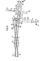
- Figure 1 shows the basic structure of a proposed sensor device. It essentially consists of the multi-core fiber 1 with the two fibers running side by side Cores 31 and 32, which are surrounded by a common cladding 2, and from the light-sensitive receiving device 4, which receives light that has passed through the cores 31 and 32 and can be determined with the changes in a parameter of this light.
- the bending sensitivity of the proposed sensor device is based on the fact that when a multi-core fiber is bent, optical properties of two cores can change relative to one another and thus also certain parameters of a light which passes through the cores. Such relative changes between two cores can, however, also be brought about by other mechanical effects on the fiber, for example by compression.
- the path lengths and refractive indices of free cores and thus the transit times of light through the two cores can change relative to one another during bending.
- the transit time differences can be measured as a physical parameter of the light that has passed through the cores and are a measure of the bending or other deformation of the fiber.
- a multi-core fiber 1 it is expedient to twist a multi-core fiber 1 along the axis A, for example by 90 °.
- the fiber is divided into two or more longitudinal areas, which differ from each other in that they are differently sensitive to the same bending.
- a twist of the fiber is assumed.
- the shortest connection V In the end section B clamped in the clamping device 100, the shortest connection V is perpendicular to the drawing plane.
- the fiber is twisted and the shortest connection V gradually rotates in this area from the vertical position to a position parallel to the plane of the drawing, which it reaches at the boundary to section, D, which adjoins section C.
- the fiber is optimally sensitive to bending parallel to the plane of the drawing, while in section B it does not react at all to such bending.
- this area B the fiber reacts optimally to bends perpendicular to the plane of the drawing, while in section D it does not react at all to such bends.
- area C the fiber is optimally sensitive to bending in different directions at an angle to the plane of the drawing.
- FIGS. 2a to 2c show cross sections through the fiber 1 in FIG. 1 along the section lines I - I to III - III.
- a multi-core fiber can also be made optimally sensitive to different bending directions if it has three or more cores which are not arranged collinear in cross section.
- An example is shown in cross section in FIG. 2d.
- the multicore fiber shown in cross section has four cores 31 to 34, which are arranged on the corners of a rectangle.
- the four sides of the rectangle and the two diagonals of the rectangle, as the shortest connections between two cores, are each optimal directions, ie if the fiber is bent in such a direction, it is optimally sensitive.
- the light-sensitive device 4 is to be designed in such a way that it can determine travel time differences between the two cores of each core pair used.
- core pairs can be used, namely the core pairs (31, 33), (33, 32), (31, 32), (32, 34), (31, 34) and 33, 34).
- the core pairs (31,33) and (33,32) are equivalent to the core pairs (31,32) and (32,34 y ) because their sides of the rectangle are parallel to each other, a core pair whose shortest connection is parallel to that of another core pair does not contribute to improving the bending sensitivity for another direction, nor would an additional core, which is collinear in cross-section to two other cores, contribute to an improvement in the bending sensitivity for another direction.
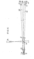
- FIG. 3 shows an embodiment of a multicore fiber 1, in which a mirror 5 is applied to an end face, which causes light that reaches it through either of the two cores 31 or 32 to be reflected back into this core and into it in the opposite direction.
- the mirror 5 can be produced in such a way that a ground or broken end of the multi-core fiber 1 is mirrored, for example by vapor deposition of a metal layer.
- the coupling of light into the cores 31 and 32 and the coupling out of the light which has passed through the cores twice take place via the same end face of the fiber. Since the light in the If a fiber passes through a core twice, the running time is twice as long as that of a fiber of the same length, in which coupling in and out takes place via different end faces.
- Travel time differences can advantageously be measured with an interferometer arrangement. It is therefore expedient in this case if a proposed sensor device is constructed as an interferometer arrangement.
- a proposed sensor device is constructed as an interferometer arrangement.
- the diameters of the cores of the multicore fiber are so small that the cores can only lead one fashion at a time. Disturbing cladding modes can be made to disappear by making the multicore fiber long enough that the cladding modes have decayed before reaching the end of the fiber and / or by providing a mode stripper to strip off interfering cladding modes on the fiber.
- a multi-core fiber 1 is used in which two cores 31 and 32 which run side by side are so far apart from one another that there is no appreciable coupling between them. Therefore, light which passes through the cores must be brought into interference outside the fiber.
- the light-sensitive device 4 has a light receiving surface 40, 410, 420 which is arranged in a beam path 400, 410, 520 of the light which has passed through the two cores 31 and 32 and is brought to interference by superimposition.
- FIG. 4 A simple implementation of such a device is shown in FIG. 4.
- the light receiving surface essentially only from a collecting screen 40, on which the interference pattern can be observed directly.
- imaging optics could be used which are to be arranged in the beam path of the light which has passed through the cores 31 and 32.
- the interference pattern that can be observed on the collecting screen changes when the phase velocity of the light that has passed through one of the two cores changes relative to the phase velocity of the light that has passed through the other core. This is equivalent to a change in the said time difference.
- the position of the dark or light structures of the interference pattern is a measure of the difference in phase velocities in the two nuclei.
- interference-capable light In order for the light that has passed through the cores to interfere, interference-capable light must be coupled into the cores. It is best to use light from a source, for example a laser. It is advantageous if the light to be coupled in is also polarized, preferably linearly polarized.
- the multi-core fiber may convert this light into elliptically polarized light, which would have the consequence that the contrast in the interference pattern would deteriorate.
- a linear polarizer 6 is arranged in the beam path of the light coupled out of the cores, which linear polarizer 6 is extremely transparent with respect to the linearly polarized light emitted by the source. parallel to the polarization of the source.
- Such a polarizer 6 is therefore provided in FIG. 3 and also in the arrangements described below.
- a light receiving surface consists of a light-sensitive surface of a light-sensitive detector, which monitors a light intensity in the interference pattern, preferably the integral intensity of the pattern.
- FIG. 1 An embodiment of a receiving device for this case is shown in FIG.
- Two detectors 41 and 42 are provided, each with a light receiving surface 410 and 420, respectively.
- the device has a beam splitter device 43, 44, which feeds light beam paths 501 and 502 emanating from different cores 31 and 32 to one of the light receiving surfaces 410 and 420, respectively.
- a mirror 43 arranged in the beam path 501 coming from the core 31 is a partially transparent mirror which is inclined at an angle of 45 ° to the axis of the beam path 501, while a mirror 44 arranged in the beam path 502 coming from the core 32 is an opaque mirror, which is is inclined to the axis of the beam path 502 and is so arranged next to the partially transparent mirror 43 that the axis of the beam path 502 reflected by the mirror 44 coincides with the axis of the beam path 501 reflected by the partially transparent mirror 43, whereby a beam path 510 from the mirror 43 to the Axis A 2 goes out, in which light from both cores 31 and 32 is superimposed. This superimposed light is supplied to the light receiving surface 410 in a concentrated manner.
- the light of the beam path 501 with the axis A 1 which has passed through the partially transparent mirror 43 is superimposed on light which is reflected by the mirror 44 th beam path, as a result of which a beam path 520 with the axis A 1 emanates from the mirror 43 and also contains light from both cores 31 and 32, which is concentrated on the light receiving surface of the other detector 42.
- the light emitted by the cores 31 and 32 as a respective divergent bundle of rays is expediently bundled by collecting optics, it being advisable to first make the divergent light parallel by a lens 50 and to pass the parallel light after passing through the beam splitter device 43, 44 to convert a second lens 51 or 52 into a convergent bundle of rays.
- the use of parallel bundled beam paths in the area of the mirror device is favorable because in this case the distance between the mirrors has no influence on the position of the real images of the end faces of the cores 31 and 32.
- the use of converging beam paths in the area between the lens 50 and the lens 51 or 52 would cause the real images of the core end faces to fall apart axially.
- an aperture 411 or 421 at the waist of the light bundled by the lens 51 or 52, which prevents interference light, and to arrange the light receiving surface 410 or 420 of the detector 41 or 42 behind the aperture.
- a multi-core fiber 1 is used, in which two cores 31 and 32 running next to one another are so closely spaced from one another that a noticeable coupling occurs between them. If the phase velocities in the two cores 31 and 32 change relative to one another in this fiber as a result of bending or deformation, then be this affects, among other things, a change in the coupling. Furthermore, as in the first implementation described above, the phase position of the two light waves emerging from the cores changes. If the intensities of these two light waves are measured, the ratio of these intensities is a measure of the relative phase velocity in the cores and thus of the said transit time difference. Accordingly, light coupled out from one core 31 and light coupled out from the other core 32 are fed separately to a light receiving surface.
- light coupled out of one core is fed to a light-sensitive surface of a light-sensitive detector and light coupled out of the other core is fed to a light-sensitive surface of another light-sensitive detector.
- FIG. 6 shows an exemplary embodiment for a corresponding receiving device.
- Light that has been coupled out from the core 31 is fed as the beam path 601 to a light receiving surface 450 of a detector 45, and light that has been coupled out from the other core 32 is separately fed via the beam path 602 to a light receiving surface 460 of a second detector 46.
- the light emerging divergently from a core is bundled by collecting optics 50 and 51 and 52, respectively.
- the lens 50 first converts each divergent bundle of light beams emerging from a core into a parallel beam and a second lens 51 or 52 concentrates the light of the parallel beam on the respective light receiving surface 450 or 460.
- the lens 50 could also be dimensioned in this way that it generates convergent tufts of rays concentrated on the light receiving surfaces 450 and 460, respectively. Lenses 51 and 52 could then omitted. Here too, glare can be reduced by glare.
- the electronic evaluation can take place in such a way that a quotient generator is connected to the two detectors 45 and 46, which forms the ratio of the detector signals.
- the cores of the multicore fiber can be so close that they touch or are even partially fused together.
- an optimal sensitivity can be achieved by a suitably chosen fiber length.
- a receiving device can also be used in this embodiment. However, the lights are preferably fed separately to a light receiving surface.
- a coupling device can be used as the coupling device, which comprises a light source and a beam splitter optics, which splits a beam path emanating from the light source into partial beam paths and which concentrates the light of a partial beam path for coupling on each core.
- a laser 71 is provided as the light source, which emits linearly polarized light.
- the beam splitter optics comprises one through which the lenses 72 and 73 comprehensive beam expansion optics expanded parallel beam path 700 of light emitted from the light source 71 light obliquely to the axis A 1 of the Parallelstrahlengahgs 700 disposed beam splitter mirror 43, an obliquely in the reflected by the beam splitter mirror 43 partial beam path 711 to its axis A 2 arranged mirror 44 and the partial beam path 701 through the Beam splitter mirror 43 transmitted light and converging lens 50 arranged in the beam path of the light reflected by the mirror 44, which concentrates the partial beams 701 and 710 on the cores 31 and 32.
- this coupling device is combined with the corresponding receiving device in such a way that the mirror device and a lens of the receiving device and the beam splitter optics of the coupling device coincide.
- This combination option is a particular advantage because it enables coupling and decoupling into a fiber with a mirror.
- an additional beam splitter mirror 720 and a light absorber are required if both superimposed beam paths 710 and 720 emitted by the common beam splitter mirror 43 are used for the measurement, as is the case in FIG. 5.
- the additional beam splitter mirror 720 is then to be arranged in one of the two beam paths 510 or 520 and the light emitted by the light source 71 is coupled in via it.
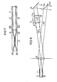
- FIG. 7 Another coupling device is shown in FIG. 7.
- beam splitter optics it comprises an optical directional coupler 8 with an input gate 811 and two output gates 812 and 822.
- the input gate 811 is to be coupled to the light source and each output gate 812 and 822 is connected to a core 31 or 32 of the multi-core fiber.
- the directional coupler is implemented with two optical fibers 81 and 82, which are located in a central section are so close that light can couple between them. When using a multi-core fiber 1, in which the cores are also so close, such a directional coupler does not bring much.
- Such a directional coupler is preferably used for multi-core fibers in which the cores are far apart.
- the distance between the optical fibers 81 and 82 can be adapted to the distance between the cores, so that a butt coupling between the optical fiber and the core is possible.
- the directional coupler 8 can. but can also be used as a beam splitter device of a receiving device and can for example replace the beam splitter device 43, 44 in FIG. 5.
- the coupling out of the light that has passed through the cores 31 and 32 and the optical fibers 81 and 82 ' can take place via the entrance gate 811, which is also the exit gate and / or a fourth gate 814.
- the lights coupled out of the gates 811 and 814 correspond to the lights guided in the beam paths 510 and 520 in FIG. 5.
- Directional couplers can be manufactured, for example, as strip-shaped waveguides using integrated technology.
- double core fibers have also been proposed as directional couplers. In principle, all such directional couplers are suitable.
- Another coupling device which is preferably used for multicore fibers with nearby cores, concentrates a light beam path emanating from a light source for coupling onto an end face of the multicore fiber in such a way that different cores are illuminated.
- An example of such a coupling device is shown in FIG. It can also be easily combined with a receiving device in the event that the same end face of the multi-core fiber is coupled in and out. This applies as with 5 both for the receiving device according to FIG. 5 and the receiving device according to FIG. 6.
- only a beam splitter mirror 76 which is to be arranged in the beam path of the decoupled light, is required, via which the light coming from a light source 740 passes over the lens 50 the nuclei can be concentrated.
- the light from the light source 74 which has passed through the beam splitter mirror 76 is expediently collected again by a light absorber.
- receiving devices and coupling devices described above which can be combined with one another, can also be used separately from one another in the event that coupling and decoupling are carried out via different end faces.
- FIG. 8 shows as an example the arrangement of a phase modulator 9 in a beam path which corresponds to that of FIG. 5.
- a phase modulator 9 can, for example, be an electro-optical effect (Pockels effect) based phase modulator can be used.
- an electric field E is generated in a KDP crystal via electrodes 91 and 92, to which a voltage U is applied, which influences the phase of the light passing through the crystal.
Landscapes
- Physics & Mathematics (AREA)
- General Physics & Mathematics (AREA)
- Optics & Photonics (AREA)
- Engineering & Computer Science (AREA)
- Electromagnetism (AREA)
- Power Engineering (AREA)
- Radar, Positioning & Navigation (AREA)
- Remote Sensing (AREA)
- Instruments For Measurement Of Length By Optical Means (AREA)
- Investigating Or Analysing Materials By Optical Means (AREA)
- Optical Couplings Of Light Guides (AREA)
- Arrangements For Transmission Of Measured Signals (AREA)
- Optical Transform (AREA)
- Length Measuring Devices By Optical Means (AREA)
Abstract
Es wird eine Sensorvorrichtung mit einer als empfindliches Element dienenden Lichtleitfaser, die einen von einem Mantel umgebenen lichtleitenden Kern aufweist, und mit einer lichtempfindlichen Einrichtung beschrieben, mit welcher Veränderungen eines bestimmten physikalischen Parameters, beispielsweise der Intensität des Lichts feststellbar sind, der sich mit einer bestimmten physikalischen Einwirkung auf die Faser ändert. Es soll eine Sensorvorrichtung dieser Art angegeben werden, die besonders empfindlich auf Verbiegungen der Faser reagiert. Zu diesem Zweck besteht die Faser aus einer Mehrkernfaser (1), die mindestens zwei nebeneinander verlaufende, von einem gemeinsamen Mantel (2) umgebene Kerne (31, 32) aufweist, und mit der lichtempfindlichen Einrichtung (4) sind Veränderungen des Parameters eines Lichtes feststellbar, das durch die beiden Kerne (31, 32) hindurchgegangen ist. Die Sensorvorrichtung kann als Sensor für Verschiebungen, Winkeländerungen oder Temperaturschwankungen, aber auch als Mikrophon verwendet werden.A sensor device is described with an optical fiber serving as a sensitive element, which has a light-conducting core surrounded by a jacket, and with a light-sensitive device with which changes in a specific physical parameter, for example the intensity of the light, can be determined, which can be determined with a specific one physical impact on the fiber changes. A sensor device of this type is to be specified which is particularly sensitive to bending of the fiber. For this purpose, the fiber consists of a multi-core fiber (1) which has at least two cores (31, 32) running next to one another and surrounded by a common sheath (2), and changes in the parameter of a light can be determined with the light-sensitive device (4) which has passed through the two cores (31, 32). The sensor device can be used as a sensor for displacements, angle changes or temperature fluctuations, but also as a microphone.
Description
Die vorliegende-Erfindung bezieht sich auf eine Sensorvorrichtung mit einer als empfindliches Element dienenden Lichtleitfaser nach dem Oberbegriff des Patentanspruchs 1.The present invention relates to a sensor device with an optical fiber serving as a sensitive element according to the preamble of patent claim 1.
Sensorvorrichtungen der eingangs genannten Art sind bekannt. Ein Beispiel für eine solche bekannte Sensorvorrichtung ist ein Ringinterferometer, das beispielsweise zum Abfühlen von Rotationsgeschwindigkeiten verwendet wird. Bei einem derartigen Ringinterferometer wird über beide..Enden der Faser Licht eingekoppelt. Das Licht,.das die Faser in einer Richtung durchlaufen hat und Licht, das die Faser in der entgegengesetzten Richtung durchlaufen hat, werden durch Überlagerung zur Interferenz gebracht und in diesem Zustand in einem Intensitätsmesser zugeführt. Es wird also die Intensität von einem durch die Faser hindurchgegangenen Licht als physikalischer Parameter gemessen. Die physikalische Einwirkung auf die Faser besteht in einer Drehbewegung der Faser. Die gemessene Intensität ändert sich mit der Winkelgeschwindigkeit dieser Drehbewegung. Die Abhängigkeit der Intensität von der Winkelgeschwindigkeit beruht auf dem Sagnac-Effekt.Sensor devices of the type mentioned are known. An example of such a known sensor device is a ring interferometer, which is used, for example, to sense rotational speeds. In such a ring interferometer, light is coupled in over both ends of the fiber. The light which has passed through the fiber in one direction and light which has passed through the fiber in the opposite direction are brought to interference by superimposition and are supplied in this state in an intensity meter. The intensity of a light that has passed through the fiber is therefore measured as a physical parameter. The physical impact on the fiber consists in a rotational movement of the fiber. The measured intensity changes with the angular velocity of this rotary movement. The dependence of the intensity on the angular velocity is based on the Sagnac effect.
Auch andere physikalische Einwirkungen auf die Faser können bestimmte Parameter von durch die Faser hindurchgegangenem Licht verändern. Beispiele dafür sind Druck-, Zug- oder auch Temperatureinwirkungen auf die Faser, welche beispielsweise die Durchlaufgeschwindigkeit des Lichts durch die Faser oder auch dessen Polarisationszustand als physikalische Parameter ändern können. Es ist bereits eine Sensorvorrichtung der eingangs genannten Art vorgeschlagen worden.(Patentanmeldung P 29 36 303.9 VPA 79 P 7138), welche auf Druck-, Zug- und auf Temperaturänderungen reagiert. Insbesondere kann eine der- . artige Sensorvorrichtung als akkustischer Sensor ange- . wendet werden.Other physical effects on the fiber can also change certain parameters of light transmitted through the fiber. Examples of this are the effects of pressure, tension or temperature on the fiber, which can, for example, change the speed at which light travels through the fiber or its state of polarization as physical parameters. It A sensor device of the type mentioned at the outset has already been proposed (patent application P 29 36 303.9 VPA 79 P 7138), which reacts to changes in pressure, tension and temperature. In particular, one of the. like sensor device as acoustic sensor. be applied.
Als bestimmter Parameter sind Parameter des hindurchgegangenen Lichts zu verstehen, die von der Meßeinrichtung tatsächlich gemessen werden. Es muß ein derartiger Parameter nicht ein unmittelbarer Parameter sein, sondern es kann dies auch ein abhängiger Parameter sein. Bei dem oben angegebenen Beispiel des Ringinterferometers wäre ein unmittelbarer Parameter die Laufzeit des durch die Faser hindurchgegangenen Lichts. Der Sagnac-Effekt bewirkt nämlich bei einer sich drehenden Faser nicht reziproke Laufzeitunterschiede zwischen Licht, das die Faser in der einen und der anderen Richtung durchläuft. Diese Laufzeitunterschiede bewirken indirekt wiederum Intensitätsänderungen im Interferenzlicht. In diesem Sinne ist die Intensität ein abhängiger Parameter.A certain parameter is to be understood as parameters of the light that has passed, which are actually measured by the measuring device. Such a parameter does not have to be an immediate parameter, but it can also be a dependent parameter. In the example of the ring interferometer given above, an immediate parameter would be the transit time of the light that passed through the fiber. The Sagnac effect causes non-reciprocal propagation time differences between light that passes through the fiber in one direction and the other with a rotating fiber. These runtime differences indirectly cause changes in intensity in the interference light. In this sense, the intensity is a dependent parameter.
Die Aufgabe der vorliegenden Erfindung besteht nun darin, eine Sensorvorrichtung der eingangs genannten Art anzugeben, die besonders empfindlich auf Verbiegungen der Faser reagiert.The object of the present invention is now to provide a sensor device of the type mentioned at the outset, which is particularly sensitive to bending of the fiber.
Diese Aufgabe wird durch die im kennzeichnenden Teil des Patentanspruchs 1 angegebenen Merkmale gelöst.This object is achieved by the features specified in the characterizing part of patent claim 1.
Eine erhöhte Biegeempfindlichkeit der vorgeschlagenen Sensorvorrichtung beruht darauf, daß bei einer Verbiegung der Mehrkernfaser in der Regel unterschiedliche physikalische Einwirkungen auf die verschiedenen Kerne ausgeübt werden, welche Parameter von durch die Kerne hindurchgegangenem Licht unterschiedlich beeinflussen.An increased bending sensitivity of the proposed sensor device is based on the fact that when the multicore fiber is bent, different physical effects are generally exerted on the different cores, which influence parameters of light transmitted through the cores differently.
Bei nur zwei parallelen Kernen hängt die Biegeempfindlichkeit stark davon ab, wie die Faser verbogen wird. Diesem Mangel kann durch die im Patentanspruch 2 und/oder die im Patentanspruch 3 angegebenen Maßnahmen abgeholfen werden.With only two parallel cores, the bending sensitivity depends strongly on how the fiber is bent. This deficiency can be remedied by the measures specified in claim 2 and / or by the measures specified in claim 3.
Bei einer besonders vorteilhaften Ausführungsform einer vorgeschlagenen Sensorvorrichtung ist die Mehrkernfaser so ausgebildet, wie es im Anspruch 4 angegeben ist. Dadurch kann die Laufzeit von Licht durch einen Kern hindurch verdoppelt oder die Faserlänge halbiert werden.In a particularly advantageous embodiment of a proposed sensor device, the multi-core fiber is designed as specified in claim 4. This can double the transit time of light through a core or halve the fiber length.
Bevorzugterweise wird eine Mehrkernfaser verwendet, welche die Merkmale des Anspruchs 5 aufweist.A multi-core fiber is preferably used, which has the features of
Zum Ausschalten störender Mantelmoden können die Maßnahmen des Anspruchs 6 ergriffen werden.The measures of claim 6 can be taken to switch off interfering cladding modes.
Eine erste vorteilhafte Ausführungsform einer vorgeschlagenen Sensorvorrichtung ist so ausgebildet, wie es in Anspruch 7 angegeben ist. Damit ist diese Ausführungsform ein Interferometer und es können vorteilhafterweise alle bei Interferometern,.insbesondere bei Ringinterferometern gewonnenen Erfahrungen ausgenutzt werden.A first advantageous embodiment of a proposed sensor device is designed as specified in claim 7. This embodiment is thus an interferometer and all the experience gained with interferometers, in particular with ring interferometers, can advantageously be used.
Die Ansprüche 8 bis 10 geben bevorzugte Ausführungsformen der Vorrichtung nach Anspruch 7 an.
Eine zweite vorteilhafte Ausführungsform einer vorgeschlagenen Sensorvorrichtung ist so ausgebildet, wie es in Anspruch 11 angegeben ist. Bei dieser Ausführungsform erfolgt bereits zwischen dem nahe benachbarten Kernen eine Überkopplung, die stark von einer Verbiegung der Mehrkernfaser abhängt. Die Intensität des aus den Kernen ausgekoppelten Lichts wird für jeden Kern getrennt gemessen. Das Verhältnis zweier getrennt gemessener Intensitäten ist ein Maß für den Grad der Verbiegung der Faser.A second advantageous embodiment of a proposed sensor device is designed as specified in claim 11. In this embodiment, there is already an overcoupling between the closely adjacent cores, which strongly depends on a bending of the multicore fiber. The intensity of the light extracted from the cores is measured separately for each core. The ratio of two measured separately Intensities are a measure of the degree of bending of the fiber.
Anspruch 12 gibt eine bevorzugte Ausführungsform einer Vorrichtung nach Anspruch 11 an.Claim 12 specifies a preferred embodiment of a device according to claim 11.
Das aus den Kernen austretende Licht ist divergent. Vielfach, beispielsweise bei Verwendung von Detektoren oder bei den Ausführungsformen nach Anspruch 11 oder 12 ist es zweckmäßig oder sogar notwendig, das divergente Licht zu bündeln, was am zweckmäßigsten durch die im Anspruch 13 angegebenen Maßnahmen erreichbar ist.The light emerging from the cores is divergent. In many cases, for example when using detectors or in the embodiments according to claim 11 or 12, it is expedient or even necessary to bundle the divergent light, which can best be achieved by the measures specified in claim 13.
Vorteilhaft ist es, eine vorgeschlagene Sensorvorrichtung so auszubilden, wie es in Anspruch 14 angegeben ist. Bei dieser Vorrichtung können störende Polarisationseffekte eliminiert werden, aber es können auch Polarisationseffekte ausgenutzt werden.It is advantageous to design a proposed sensor device as specified in claim 14. In this device, disruptive polarization effects can be eliminated, but polarization effects can also be used.
Einkoppelvorrichtungen in vorgeschlagenen Sensorvorrichtungen werden zweckmäßigerweise so ausgebildet, wie es in den Ansprüchen 15 bis 18 angegeben ist. Sie können besonders vorteilhaft bei einer Mehrkernfaser mit Spiegel, wie sie in Anspruch 4 angegeben ist, eingesetzt werden. Bei einer solchen Faser wird in der Regel Licht über die gleiche Stirnfläche ein- und auch wieder ausgekoppelt. In diesem Fall muß eine Einkoppelvorrichtung so ausgebildet sein, daß Messungen am ausgekoppelten Licht vorgenommen werden können und daß der zu messende Parameter nicht beeinträchtigt wird. Mit den Einkoppelvorrichtungen nach den Ansprüchen 14 bis 18 können diese Forderungen erfüllt werden.Coupling devices in proposed sensor devices are expediently designed as specified in claims 15 to 18. They can be used particularly advantageously in the case of a multi-core fiber with a mirror, as specified in claim 4. With such a fiber, light is usually coupled in and out again via the same end face. In this case, a coupling device must be designed in such a way that measurements can be carried out on the coupled light and that the parameter to be measured is not impaired. With the coupling devices according to claims 14 to 18, these requirements can be met.
Die Ausführungsformen nach den Ansprüchen 14 bis 17 werden vorzugsweise bei einer Mehrkernfaser mit weit voneinander entfernten Kernen verwendet, während die Ausführungsform nach Anspruch 18 vorzugsweise bei einer Mehrkernfaser mit nahe benachbarten Kernen verwendet wird.The embodiments according to claims 14 to 17 are preferably used for a multi-core fiber with widely spaced cores, while the embodiment according to claim 18 is preferably used for one Multi-core fiber with closely adjacent cores is used.
Anspruch 19 gibt eine Ausführungsform einer vorgeschlagenen Sensorvorrichtung an, mit welcher einem Licht, das aus einem Kern ausgekoppelt worden ist, eine Phasenverschiebung, vorzugsweise eine periodisch schwankende Phasenverschiebung erteilbar ist. Durch diese Maßnahmen kann eine auftretende Phasenverschiebung zwischen den aus verschiedenen Kernen ausgekoppelten Lichtern ausgeglichen werden und meßtechnisch ausgenutzt werden und es kann bei Aufprägung einer schwankenden Phasenverschiebung zusätzlich Information über die Richtung einer Verbiegung der Mehrkernfaser gewonnen werden.Claim 19 specifies an embodiment of a proposed sensor device by means of which a phase shift, preferably a periodically fluctuating phase shift, can be given to a light that has been coupled out of a core. These measures can compensate for a phase shift that occurs between the lights coupled out from different cores and can be used for measurement purposes, and additional information about the direction of a bending of the multicore fiber can be obtained when a fluctuating phase shift is impressed.
Eine vorgeschlagene Sensorvorrichtung spricht nicht nur auf Verbiegungen der Mehrkernfaser,sondern auch auf andere Deformationen, beispielsweise Zusammendrückungen,an. Eine vorgeschlagene Sensorvorrichtung kann zum Aufbau verschiedenster Sensoren verwendet werden, beispielsweise als Sensor für Verschiebungen oder Winkeländerungen, in Verbindung mit einem Bimetallstreifen als Temperaturfühler oder auch als Mikrophon.A proposed sensor device responds not only to bending of the multi-core fiber, but also to other deformations, for example compression. A proposed sensor device can be used to set up a wide variety of sensors, for example as a sensor for displacements or changes in angle, in conjunction with a bimetal strip as a temperature sensor or as a microphone.
Die Erfindung wird anhand der beigefügten Figuren in der nun folgenden Beschreibung näher erläutert. Es zeigen
- Figur 1 ein eingespanntes Endstück einer um ihre Achse verdrehten Mehrkernfaser, neben der eine Empfangseinrichtung angeordnet ist, welche Licht, das aus den Kernen der Mehrkernfaser ausgekoppelt worden ist, empfängt;
- die Figuren 2a bis 2c Querschnitte durch die Mehrkernfaser.in Figur 1 längs der Schnittlinien I - I, II - II bzw. III - III, welche die Anordnung der Kerne in der verdrehten Faser an verschiedenen Stellen zeigen, und die Figur 2d einen Querschnitt durch eine Mehrkernfaser mit vier Kernen;
- Figur 3 eine Mehrkernfaser, die an einem Ende eingespannt ist und auf deren Stirnfläche am anderen Ende ein Spiegel aufgebracht ist;
- Figur 4 ein Endstück einer Mehrkernfaser mit zwei Kernen, die soweit voneinander entfernt sind, daß keine nennenswerte Überkopplung auftritt und eine Empfangseinrichtung mit Auffangschirm, welcher das aus den Kernen ausgekoppelte und zur Interferenz gebrachte Licht empfängt;
Figur 5 eine Empfangseinrichtung und eine damit kombinierte Einkoppelvorrichtung für eine Mehrkernfaser, bei der über die gleiche Stirnfläche ein- und ausgekoppelt wird und die besonders für Mehrkernfasern mit weit voneinander angeordneten Kernen geeignet sind;- Figur 6 eine Empfangseinrichtung und eine damit kombinierte Einkoppelvorrichtung für eine Mehrkernfaser, bei der ebenfalls über die gleiche Stirnfläche ein- und ausgekoppelt wird und die besonders für Mehrkernfasern mit nahe beieinander liegenden Kernen geeignet sind;
- Figur 7 eine aus einem optischen Richtkoppler bestehende Einkoppelvorrichtung;
Figur 8 einen Ausschnitt aus einer Empfangseinrichtung, wie sie inFigur 5 dargestellt ist, bei der in einem Strahlengang ein optischer Phasenmodulator angeordnet ist.
- 1 shows a clamped end piece of a multicore fiber rotated about its axis, next to which a receiving device is arranged, which receives light that has been coupled out of the cores of the multicore fiber;
- Figures 2a to 2c cross-sections through the multi-core fiber in Figure 1 along the section lines I - I, II - II and III - III, which the arrangement of the cores in the twisted fiber to various NEN points, and Figure 2d shows a cross section through a multi-core fiber with four cores;
- FIG. 3 shows a multi-core fiber which is clamped at one end and a mirror is applied to the end face of the other end;
- FIG. 4 shows an end piece of a multi-core fiber with two cores which are so far apart from one another that no significant overcoupling occurs and a receiving device with a catch screen which receives the light which is coupled out of the cores and brought to interference;
- FIG. 5 shows a receiving device and a coupling device for a multi-core fiber combined therewith, in which coupling and uncoupling takes place via the same end face and which are particularly suitable for multi-core fibers with cores arranged far apart;
- FIG. 6 shows a receiving device and a coupling device for a multi-core fiber combined therewith, in which coupling and uncoupling are likewise carried out via the same end face and which are particularly suitable for multi-core fibers with cores lying close to one another;
- FIG. 7 a coupling device consisting of an optical directional coupler;
- 8 shows a section of a receiving device, as shown in FIG. 5, in which an optical phase modulator is arranged in a beam path.
Die Figuren sind nicht maßstabsgetreu. Die Dicke der Mehrkernfasern sind stark übertrieben dargestellt.The figures are not to scale. The thickness of the multi-core fibers are shown exaggerated.
Figur 1 zeigt den Grundaufbau einer vorgeschlagenen Sensorvorrichtung. Sie besteht im wesentlichen aus der Mehrkernfaser 1 mit den beiden nebeneinander verlaufenden Kernen 31 und 32, die.von einem gemeinsamen Mantel 2 umgeben sind, und aus der lichtempfindlichen Empfangseinrichtung 4, welche Licht, das durch die Kerne 31 und 32 hindurchgegangen ist, empfängt und mit der Veränderungen eines Parameters dieses Lichts feststellbar sind.Figure 1 shows the basic structure of a proposed sensor device. It essentially consists of the multi-core fiber 1 with the two fibers running side by
Die Biegeempfindlichkeit der vorgeschlagenen Sensorvorrichtung beruht darauf, daß bei einer Verbiegung einer Mehrkernfaser sich optische Eigenschaften zweier Kerne relativ zueinander ändern können und damit auch bestimmte Parameter eines Lichts, das die bei den Kerne durchläuft. Derartige relative Änderungen zweier Kerne können allerdings auch durch andere mechanische Einwirkungen auf die Faser, beispielsweise durch ein Zusammendrücken bewirkt werden.The bending sensitivity of the proposed sensor device is based on the fact that when a multi-core fiber is bent, optical properties of two cores can change relative to one another and thus also certain parameters of a light which passes through the cores. Such relative changes between two cores can, however, also be brought about by other mechanical effects on the fiber, for example by compression.
Beispielsweise können bei einer Verbiegung sich Weglängen und Brechzahlen freier Kerne und damit auch Laufzeiten von Licht durch die beiden Kerne relativ zueinander ändern. Die Laufzeitdifferenzen können als physikalischer Parameter des durch die Kerne hindurchgegangenen Lichts gemessen werden und sind ein Maß für die Verbiegung oder anderweitige Deformation der Faser.For example, the path lengths and refractive indices of free cores and thus the transit times of light through the two cores can change relative to one another during bending. The transit time differences can be measured as a physical parameter of the light that has passed through the cores and are a measure of the bending or other deformation of the fiber.
Größte Laufzeitunterschiede werden in einer Krümmung dann erhalten, wenn die kürzeste Verbindung V zwischen zwei Kernen 31 und 32 in Richtung eines Krümmungsradius R verläuft. Dieser Fall ist in der Figur 2c im Querschnitt dargestellt. Verläuft in diesem Fall die Achse A der Faser auch noch zwischen den beiden Kernen, so wird der radial äußere Kern gedehnt und der radial innere Kern gestaucht, wodurch besonders große Laufzeitunterschiede erhalten werden.The greatest differences in transit time are obtained in a curvature if the shortest connection V between two
Verläuft dagegen die kürzeste Verbindung V senkrecht zum Krümmungsradius R, so werden keine Laufzeitunterschiede erzeugt. Dieser ungünstigste Fall ist in der Figur 2c im Querschnitt durch die Mehrkernfaser 1 dargestellt.If, on the other hand, the shortest connection V runs perpendicular to the radius of curvature R, there are no runtime differences generated. This worst case is shown in FIG. 2c in cross section through the multi-core fiber 1.
Es ist zweckmäßig, eine Mehrkernfaser 1 längs der Achse A zu verdrehen, beispielsweise um 90°. Die Faser wird so in zwei oder mehrere Längsbereiche unterteilt, die sich dadurch voneinander unterscheiden, daß sie gegen die gleiche Verbiegung unterschiedlich empfindlich sind. Bei der Mehrkernfaser 1 in Figur 1 ist eine Verdrehung der Faser angenommen. In dem in der Einspannvorrichtung 100 eingespannten Endabschnitt B steht die kürzeste Verbindung V senkrecht auf der Zeichenebene. In dem daran anschließenden Abschnitt C ist die Faser verdreht und die kürzeste Verbindung V dreht sich in diesem Bereich allmählich von der vertikalen Stellung in eine zur Zeichenebene parallele Stellung, die sie an der Grenze zum Abschnitt, D erreicht, der sich an den Absshnitt C anschließtIn diesem Bereich ist die Faser für Verbiegungen parallel zur Zeichenebene optimal empfindlich, während sie im Abschnitt B auf solche Verbiegungen überhaupt nicht reagiert. In diesem Bereich B reagiert die Faser optimal auf Verbiegungen senkrecht zur Zeichenebene, während sie im Abschnitt D auf solche Verbiegungen überhaupt nicht reagiert. Im Bereich C ist die Faser für Verbiegungen in verschiedenen Richtungen schräg zur Zeichenebene optimal empfindlich.It is expedient to twist a multi-core fiber 1 along the axis A, for example by 90 °. The fiber is divided into two or more longitudinal areas, which differ from each other in that they are differently sensitive to the same bending. In the multi-core fiber 1 in Figure 1, a twist of the fiber is assumed. In the end section B clamped in the
Die Figuren 2a bis 2c zeigen der Reihe nach Querschnitte durch die Faser 1 in Figur 1 längs den Schnittlinien I - I bis III - III.FIGS. 2a to 2c show cross sections through the fiber 1 in FIG. 1 along the section lines I - I to III - III.
Eine Mehrkernfaser kann auch für verschiedene Biegerichtungen optimal empfindlich gemacht werden, wenn sie drei oder mehrere Kerne aufweist, die im Querschnitt nicht kollinear angeordnet sind. In der Figur 2d ist im Querschnitt ein Beispiel gezeigt. Die im Querschnitt dargestellte Mehrkernfaser weist vier Kerne 31 bis 34 auf, die auf den Ecken eines Rechtecks angeordnet sind. Die vier Rechteckseiten und die beiden Diagonalen des Rechtecks sind als kürzeste Verbindungen zwischen zwei Kernen jeweils optimale Richtungen, d.h. bei einer Verbiegung der Faser in einer solchen Richtung ist sie optimal empfindlich. Allerdings ist die lichtempfindliche Einrichtung 4 so auszubilden, daß sie Laufzeitunterschiede zwischen den beiden Kernen eines jeden verwendeten Kernpaares feststellen kann. Bei der Mehrkernfaser nach Figur 2d können sechs Kernpaare verwendet werden, nämlich die Kernpaare (31, 33), (33, 32), (31, 32), (32, 34), (31, 34) und 33,34). Die Kernpaare(31,33) und(33,32) sind wie die Kernpaare(31,32) ünd(32,34y gleichwertig, weil ihre Rechteckseiten jeweils parallel zueinander verlaufen. Ein Kernpaar, dessen kürzeste Verbindung parallel zu derjenigen eines anderen Kernpaares verläuft, trägt zur Verbesserung der Biegeempfindlichkeit für eine andere Richtung nichts bei. Genauso wenig würde ein zusätzlicher Kern der im Querschnitt kollinear zu zwei anderen Kernen angeordnet ist, zu einer Verbesserung der Biegeempfindlichkeit für eine andere Richtung beitragen.A multi-core fiber can also be made optimally sensitive to different bending directions if it has three or more cores which are not arranged collinear in cross section. An example is shown in cross section in FIG. 2d. The multicore fiber shown in cross section has four
In der Figur 3 ist eine Ausführungsform einer Mehrkernfaser 1 dargestellt, bei der auf einer Stirnfläche ein Spiegel 5 aufgebracht ist, der bewirkt, daß Licht, das durch jeden der beiden Kerne 31 oder 32 zu ihm gelangt, in diesen Kern zurückreflektiert wird und ihn in der entgegengesetzten Richtung durchläuft.FIG. 3 shows an embodiment of a multicore fiber 1, in which a
Der Spiegel 5 kann so hergestellt werden, daß ein abgeschliffenes oder gut gebrochenes Ende der Mehrkernfaser 1 verspiegelt wird, beispielsweise durch Aufdampfen einer Metallschicht.The
Bei der Faser nach der Figur 3 erfolgt die Einkoppelung von Licht in die Kerne 31 und 32 und die Auskoppelung des Lichts, das die Kerne zweimal durchlaufen hat, über die gleiche Stirnfläche der Faser. Da das Licht in dieser Faser einen Kern zweimal durchläuft, ist die Laufzeit doppelt so groß als bei einer gleichlangen Faser, bei der über verschiedene Stirnflächen ein- und ausgekoppelt wird.In the fiber according to FIG. 3, the coupling of light into the
Laufzeitunterschiede können vorteilhaft mit einer Interferometeranordnung gemessen werden. Es ist also für diesen Fall zweckmäßig, wenn eine vorgeschlagene Sensorvorrichtung als Interferometeranordnung aufgebaut ist.In diesem Zusammenhang ist zu erwähnen, daß es auch hier, ähnlich wie bei vorgeschlagenen oder bekannten Ringinterferometern, vorteilhaft ist, wenn die Durchmesser der Kerne der Mehrkernfaser so klein sind, daß die Kerne jeweils nur einen Mode führen können. Störende Mantelmoden können zum Verschwinden gebracht werden, indem die Mehrkernfaser so lang gemacht wird, daß die Mantelmoden abgeklungen sind, bevor sie das Ende der Faser erreichen und/oder indem ein Modenabstreifer zum Abstreifen störender Mantelmoden an der Faser vorgesehen ist.Travel time differences can advantageously be measured with an interferometer arrangement. It is therefore expedient in this case if a proposed sensor device is constructed as an interferometer arrangement. In this context it should be mentioned that, similarly to proposed or known ring interferometers, it is also advantageous here if the diameters of the cores of the multicore fiber are so small that the cores can only lead one fashion at a time. Disturbing cladding modes can be made to disappear by making the multicore fiber long enough that the cladding modes have decayed before reaching the end of the fiber and / or by providing a mode stripper to strip off interfering cladding modes on the fiber.
Es gibt mehrere Möglichkeiten, eine vorgeschlagene Sensorvorrichtung als Interferometeranordnung aufzubauen. Bei einer Ausführungsform wird eine Mehrkernfaser 1 verwendet, bei der zwei nebeneinander verlaufende Kerne 31 und 32 so weit voneinander entfernt sind, daß keine nennenswerte Überkopplung zwischen ihnen auftritt.. Daher muß Licht, welches die Kerne durchläuft, außerhalb der Faser zur Interferenz gebracht werden. Dies geschieht am zweckmäßigsten so, daß die lichtempfindliche Einrichtung 4 eine Lichtempfangsfläche 40, 410, 420 aufweist, welche in einem Strahlengang 400, 410, 520 des durch die beiden Kerne 31 und 32 hindurchgegangenen und durch Überlagerung zur Interferenz gebrachten Lichts angeordnet ist.There are several options for constructing a proposed sensor device as an interferometer arrangement. In one embodiment, a multi-core fiber 1 is used in which two
Eine einfache Realisierung einer solchen Einrichtung ist in der Figur 4 dargestellt. Hier besteht die Lichtempfangsfläche im wesentlichen nur aus einem Auffangschirm 40, auf dem das Interferenzmuster unmittelbar beobachtbar ist. Selbstverständlich könnten zur Verbesserung der Bildqualität, zur Vergrößerung oder Verkleinerung des Interferenzbildes, Abbildungsoptiken verwendet werden, die im Strahlengang des durch die Kerne 31 und 32 hindurchgegangenen Lichts anzuordnen sind. Das auf dem Auffangschirm beobachtbare Interferenzmuster ändert sich, wenn die Phasengeschwindigkeit des durch einen der beiden Kerne hindurchgegangenen Lichts relativ zur Phasengeschwindigkeit des durch den anderen Kern hindurchgegangenen Lichts ändert. Dies ist gleichbedeutend mit einer Änderung der besagten Laufzeitdifferenz. Die Lage der dunklen oder hellen Strukturen des Interferenzmusters ist ein Maß für den Unterschied der Phasengeschwindigkeiten in beiden Kernen.A simple implementation of such a device is shown in FIG. 4. Here is the light receiving surface essentially only from a
Damit das durch die Kerne hindurchgegangene Licht interferieren kann, muß interferenzfähiges Licht in die Kerne eingekoppelt werden. Am besten wird dazu Licht einer Quelle, beispielsweise eines Lasers, verwendet. Günstig ist es dabei, wenn das einzukoppelnde Licht auch polarisiert ist, am besten linear polarisiert.In order for the light that has passed through the cores to interfere, interference-capable light must be coupled into the cores. It is best to use light from a source, for example a laser. It is advantageous if the light to be coupled in is also polarized, preferably linearly polarized.
Bei Verwendung von linear polarisiertem Licht kann es vorkommen, daß die Mehrkernfaser dieses Licht in elliptisch polarisiertes Licht umwandelt, was zur Folge hätte, daß sich der Kontrast im Interferenzmuster verschlechtern würde. Es ist daher zur Erzielung eines guten Kontrastes vorteilhaft, wenn im Strahlengang des aus den Kernen ausgekoppelten Lichts ein linearer Polarisator 6 angeordnet wird, der bezüglich des von der Quelle ausgesandten linear polarisierten Lichts auf größte Durchlässigkeit, d.h. parallel zur Polarisation der Quelle, eingestellt ist. In der Figur 3 und auch in den im folgenden beschriebenen Anordnungen ist deshalb ein derartiger Polarisator 6 vorgesehen.If linearly polarized light is used, the multi-core fiber may convert this light into elliptically polarized light, which would have the consequence that the contrast in the interference pattern would deteriorate. In order to achieve a good contrast, it is therefore advantageous if a linear polarizer 6 is arranged in the beam path of the light coupled out of the cores, which linear polarizer 6 is extremely transparent with respect to the linearly polarized light emitted by the source. parallel to the polarization of the source. Such a polarizer 6 is therefore provided in FIG. 3 and also in the arrangements described below.
Anstelle einer visuellen Beobachtung oder Überwachung des Interferenzmusters mit einem Auffangschirm kann auch eine elektronische Überwachung des Interferenzmusters verwendet werden. In einem solchen Fall besteht eine Lichtempfangsfläche aus einer lichtempfindlichen Fläche eines lichtempfindlichen Detektors, der eine Lichtintensität im Interferenzmuster, vorzugsweise die integrale Intensität des Musters, überwacht.Instead of visual observation or monitoring of the interference pattern with a catch screen, electronic monitoring of the interference pattern can also be used. In such a case, a light receiving surface consists of a light-sensitive surface of a light-sensitive detector, which monitors a light intensity in the interference pattern, preferably the integral intensity of the pattern.
Eine Ausführungsform einer Empfangseinrichtung für diesen Fall ist in der Figur 5 dargestellt. Es sind zwei Detektoren 41 und 42 mit jeweils einer Lichtempfangsfläche 410 bzw. 420 vorgesehen. Die Einrichtung weist eine Strahlteilervorrichtung 43,44 auf, welche von verschiedenen Kernen 31 und 32 ausgehende Lichtstrahlengänge 501 bzw. 502 überlagert jeweils einer der Lichtempfangsflächen 410 bzw. 420 zuführt.An embodiment of a receiving device for this case is shown in FIG. Two
Ein in dem vom Kern 31 herkommenden Strahlengang 501 angeordneter Spiegel 43 ist ein teildurchlässiger Spiegel , der im Winkel von 45° zur Achse des Strahlengangs 501 geneigt ist, während ein in dem vom Kern 32 herkommenden Strahlengang 502 angeordneter Spiegel 44 ein undurchlässiger Spiegel ist, welcher so zur Achse des Strahlengangs 502 geneigt ist und so neben dem teildurchlässigen Spiegel 43 angeordnet ist, daß die Achse des vom Spiegel 44 reflektierten Strahlengangs 502 mit der Achse des vom teildurchlässigen Spiegel 43 reflektierten Strahlengangs 501 zusammenfällt, wodurch vom Spiegel 43 ein Strahlengang 510 mit der Achse A2 ausgeht, in dem Licht aus beiden Kernen 31 und 32 überlagert ist. Dieses überlagerte Licht wird der Lichtempfangsfläche 410 konzentriert zugeführt.A
Dem durch den teildurchlässigen Spiegel 43 hindurchgegangenen Licht des Strahlengangs 501 mit der Achse A1 überlagert sich Licht des vom Spiegel 44 reflektierten Strahlengangs, wodurch vom Spiegel 43 ein Strahlengang 520 mit der Achse A1 ausgeht, der ebenfalls Licht aus beiden Kernen 31 und 32 enthält, das auf die Lichtempfangsfläche des anderen Detektors 42 konzentriert wird.The light of the
Das von den Kernen 31 und 32 als jeweils divergentes Strahlenbüschel ausgesandte Licht wird zweckmäßigerweise durch eine sammelnde Optik gebündelt, wobei es sich empfiehlt, das divergente Licht zunächst durch eine Linse 50 parallel zu machen und das parallele Licht nach Durchgang durch die Strahlteilervorrichtung 43, 44 durch eine zweite Linse 51 bzw. 52 in ein konvergentes Strahlenbüschel umzuwandeln. Die Verwendung von parallel gebündelten Strahlengängen im Bereich der Spiegelvorrichtung ist günstig, weil in diesem Fall der Abstand zwischen den Spiegeln keinen Einfluß auf die Lage der reellen Bilder der Stirnflächen der Kerne 31 und 32 hat. Die Verwendung von konvergierenden Strahlengängen im Bereich zwischen der Linse 50 und der Linse 51 bzw. 52. würde bewirken, daß die reellen Bilder der Kernstirnflächen axial auseinanderfallen.The light emitted by the
Es ist auch zweckmäßig, in der Taille des von der Linse' 51 bzw. 52 gebündelten Lichts eine Blende 411 bzw. 421 zu verwenden, welche Störlicht abhält.und die Lichtempfangsfläche 410 bzw. 420 des Detektors 41 bzw. 42 hinter der Blende anzuordnen.It is also expedient to use an
Bei einer anderen möglichen Ausführungsform einer Interferometers wird eine Mehrkernfaser 1 verwendet, bei der zwei nebeneinander verlaufende Kerne 31 und 32 einen so geringen Abstand voneinander aufweisen, daß eine nennenswerte Überkopplung zwischen ihnen auftritt. Wenn sich in dieser Faser infolge einer Verbiegung oder Deformation die Phasengeschwindigkeiten in den beiden Kernen 31 und 32 relativ zueinander ändert, so bewirkt dies unter anderem eine Änderung der Überkopplung. Ferner ändert sich wie in der oben beschriebenen ersten Realisierung die Phasenlage der beiden aus den Kernen austretenden Lichtwellen. Werden die Intensitäten dieser beiden Lichtwellen gemessen, so ist das Verhältnis dieser Intensitäten ein Maß für die relative Phasengeschwindigkeit in den Kernen und damit für die besagte Laufzeitdifferenz. Dementsprechend werden aus einem Kern 31 ausgekoppeltes Licht und aus dem anderen Kern 32 ausgekoppeltes Licht voneinander getrennt einer Lichtempfangsfläche zugeführt.In another possible embodiment of an interferometer, a multi-core fiber 1 is used, in which two
Für eine elektronische Auswertung ist es wiederum zweckmäßig, wenn aus einem Kern ausgekoppeltes Licht einer lichtempfindlichen Fläche eines lichtempfindlichen Detektors und aus dem anderen Kern ausgekoppeltes Licht einer lichtempfindlichen Fläche eines anderen lichtempfind-* lichen Detektors zugeführt wird.For electronic evaluation, it is again expedient if light coupled out of one core is fed to a light-sensitive surface of a light-sensitive detector and light coupled out of the other core is fed to a light-sensitive surface of another light-sensitive detector.
In der Figur 6 ist ein Ausführungsbeispiel für eine entsprechende Empfangseinrichtung dargestellt. Licht, das aus dem Kern 31 ausgekoppelt wörden ist, wird als Strahlengang 601 einer Lichtempfangsfläche 450 eines Detektors 45 zugeführt und Licht, das aus dem anderen Kern 32 ausgekoppelt worden ist, wird getrennt über den Strahlengang 602 einer Lichtempfangsfläche 460 eines zweiten Detektors 46 zugeführt. Auch hier wird das divergent aus einem Kern austretende Licht durch eine sammelnde Optik 50 und 51 bzw. 52 gebündelt. Die Linse 50 wandelt zunächst jedes divergente Lichtstrahlbüschel, welches aus einem Kern austritt, in ein Parallelstrahlbündel um und eine zweite Linse 51. bzw. 52 konzentriert das Licht des Parallelstrahlbündels auf die jeweilige Lichtempfangsfläche 450 bzw. 460. Die Linse 50 könnte auch so bemessen sein, daß sie konvergente Strahlenbüschel erzeugt, die auf die Lichtempfangsflächen 450 bzw. 460 konzentriert sind. Die Linsen 51 und 52 könnten dann entfallen. Auch hier kann Störlicht durch Blenden vermindert werden. Die elektronische Auswertung kann so erfolgen, daß an die beiden Detektoren 45 und 46 ein Quotientenbildner angeschlossen wird, der das Verhältnis der Detektorsignale bildet.FIG. 6 shows an exemplary embodiment for a corresponding receiving device. Light that has been coupled out from the
Die Kerne der Mehrkernfaser können sich so nahe sein, daß sie sich berühren oder gar teilweise miteinander verschmolzen sind.The cores of the multicore fiber can be so close that they touch or are even partially fused together.
Bei der soeben beschriebenen Ausführungsform kann eine optimale Empfindlichkeit durch eine geeignet gewählte Faserlänge erzielt werden.In the embodiment just described, an optimal sensitivity can be achieved by a suitably chosen fiber length.
Es .sei darauf hingewiesen, daß hei der soeben beschriebenen Ausführungsform aus einem Kern 31 ausgekoppeltes Licht und aus dem naheliegenden anderen Kern 32 ausgekoppeltes Licht nicht notwendig voneinander getrennt einer Lichtempfangsfläche zugeführt werden müssen.It is pointed out that in the embodiment just described, light coupled out of one
Es kann auch bei dieser Ausführungsform eine Empfangseinrichtung nach Figur 5 verwendet werden. Vorzugsweise werden aber die Lichter getrennt einer Lichtempfangsfläche zugeführt.A receiving device according to FIG. 5 can also be used in this embodiment. However, the lights are preferably fed separately to a light receiving surface.
Als Einkoppelvorrichtung kann bei beiden vorstehend beschriebenen möglichen Ausführungsformen eine Einkoppelvorrichtung verwendet werden, die eine Lichtquelle und eine Strahlteileroptik umfaßt, welche einen von der Lichtquelle ausgehenden Strahlengang in Teilstrahlengänge aufspaltet und welche auf jeden Kern das Licht eines Teilstrahlengangs zum Einkoppeln konzentriert.In the two possible embodiments described above, a coupling device can be used as the coupling device, which comprises a light source and a beam splitter optics, which splits a beam path emanating from the light source into partial beam paths and which concentrates the light of a partial beam path for coupling on each core.
Eine bevorzugte Ausführungsform einer solchen Einkoppelvorrichtung geht aus der bereits erwähnten Figur 5 hervor. Als Lichtquelle ist ein Laser 71 vorgesehen, der linear polarisiertes Licht aussendet. Die Strahlteileroptik umfaßt einen in den durch eine die Linsen 72 und 73 umfassende Strahlaufweitungsoptik aufgeweiteten Parallelstrahlengang 700 des von der Lichtquelle 71 ausgesandten Lichts schräg zur Achse A1 des Parallelstrahlengahgs 700 angeordneten Strahlteilerspiegel 43, einen in dem vom Strahlteilerspiegel 43 reflektierten Teilstrahlengang 711 schräg zu dessen Achse A2 angeordneten Spiegel 44 und eine im Teilstrahlengang 701 des durch den Strahlteilerspiegel 43 hindurchgegangenen Lichts und im Strahlengang des vom Spiegel 44 reflektierten Lichts angeordnete Sammellinse 50, welche die Teilstrahlenbündel 701 und 710 auf die Kerne 31 und 32 konzentriert. Wie aus der Figur 5 unmittelbar zu entnehmen ist , ist diese Einkoppelvorrichtung mit der entsprechenden Empfangseinrichtung derart kombiniert, daß die Spiegelvorrichtung und eine Linse der Empfangseinrichtung und die Strahlteileroptik der Einkoppelvorrichtung zusammenfallen. Diese Kombinationsmöglichkeit ist ein besonderer Vorteil, weil so das Ein- und Auskoppeln in.eine Faser mit Spiegel ermöglicht wird.A preferred embodiment of such a coupling device can be seen from FIG. 5 already mentioned. A laser 71 is provided as the light source, which emits linearly polarized light. The beam splitter optics comprises one through which the
Allerdings ist ein zusätzlicher Strahlteilerspiegel 720 und ein Lichtabsorber erforderlich, wenn beide vom gemeinsamen Strahlteilerspiegel 43 ausgesandten überlagerten Strahlengänge 710 und 720 für die Messung ausgenutzt werden, wie es in der Figur 5 der Fall ist. Der zusätzliche Strahlteilerspiegel 720 ist dann in einem der beiden Strahlengänge 510 oder 520 anzuordnen und über ihn wird das von der Lichtquelle 71 ausgestrahlte Licht eingekoppelt.However, an additional
Eine andere Einkoppelvorrichtung ist in der Figur 7 dargestellt. Sie umfaßt als Strahlteileroptik einen optischen Richtkoppler 8 mit einem Eingangstor 811 und zwei Ausgangstoren 812 und 822. Das Eingangstor 811 ist an die Lichtquelle anzukoppeln und jedes Ausgangstor 812 und 822 an je einen Kern 31 bzw. 32 der Mehrkernfaser. Der Richtkoppler ist mit zwei Lichtwellenleitern 81 und 82 realisiert, die sich in einem Mittelabschnitt so nahe sind, daß Licht zwischen ihnen überkoppeln kann. Bei Verwendung einer Mehrkernfaser 1, bei denen sich die Kerne ebenfalls so nahe sind, bringt daher ein solcher Richtkoppler nicht besonders viel. Ein solcher Richtkoppler wird bevorzugt für Mehrkernfasern verwendet, bei denen die Kerne weit auseinanderliegen. Der Abstand der Lichtwellenleiter 81 und 82 kann dem Abstand der Kerne angepaßt werden, so daß eine Stoßkopplung zwischen Lichtwellenleiter und Kern möglich wird.Another coupling device is shown in FIG. 7. As beam splitter optics, it comprises an optical
Der Richtkoppler 8 kann. aber auch als Strahlteilervorrichtung einer Empfangseinrichtung verwendet werden und kann beispielsweise die Strahlteilervorrichtung 43, 44 in Figur 5 ersetzen. Das Auskoppeln des durch die Kerne 31 und 32 und die Lichtwellenleiter 81 und 82' hindurchgegangenen Lichts kann über das Eingangstor 811, das zugleich Ausgangstor ist und/oder ein viertes Tor 814 erfolgen. Die aus den Toren 811 und 814 ausgekoppelten Lichter entsprechen den in den Strahlengängen 510 und 520 in Figur 5 geführten Lichtern.The
Richtkoppler können beispielsweise als streifenförmige Wellenleiter in integrierter Technik hergestellt werden. Es sind aber auch schon Doppelkernfasern als Richtkoppler vorgeschlagen worden. Prinzipiell sind alle solchen Richtkoppler geeignet.Directional couplers can be manufactured, for example, as strip-shaped waveguides using integrated technology. However, double core fibers have also been proposed as directional couplers. In principle, all such directional couplers are suitable.
Eine weitere Einkoppelvorrichtung, welche vorzugsweise bei Mehrkernfasern mit sich naheliegenden Kernen verwendet wird, konzentriert einen von einer Lichtquelle ausgehenden Lichtstrahlengang zum Einkoppeln so auf eine Stirnfläche der Mehrkernfaser, daß verschiedene Kerne beleuchtet werden. In der Figur 6 ist ein Beispiel einer solchen Einkoppelvorrichtung gezeigt. Auch sie ist für den Fall, daß über die gleiche Stirnfläche der Mehrkernfaser ein- und ausgekoppelt wird, mit einer Empfangseinrichtung ohne weiteres kombinierbar. Dies gilt wie bei der Einkoppelvorrichtung nach Figur 5 sowohl für die Empfangseinrichtung nach Figur 5 als auch die Empfangseinrichtung nach Figur 6. In jedem Fall ist lediglich ein im Strahlengang des ausgekoppelten Lichts anzuordnender Strahlteilerspiegel 76 erforderlich, über den das von einer Lichtquelle 740 herkommende Licht über die Linse 50 auf die Kerne konzentriert werden kann. Das durch den Strahlteilerspiegel 76 hindurchgegangene Licht der Lichtquelle 74 wird zweckmäßigerweise wieder durch einen Lichtabsorber aufgefangen.Another coupling device, which is preferably used for multicore fibers with nearby cores, concentrates a light beam path emanating from a light source for coupling onto an end face of the multicore fiber in such a way that different cores are illuminated. An example of such a coupling device is shown in FIG. It can also be easily combined with a receiving device in the event that the same end face of the multi-core fiber is coupled in and out. This applies as with 5 both for the receiving device according to FIG. 5 and the receiving device according to FIG. 6. In any case, only a
Selbstverständlich können die vorstehend beschriebenen und miteinander kombinierbaren Empfangseinrichtungen und Einkoppelvorrichtungen in dem Fall, daß über verschiedene Stirnflächen ein- und ausgekoppelt wird, auch voneinander getrennt verwendet.werden.Of course, the receiving devices and coupling devices described above, which can be combined with one another, can also be used separately from one another in the event that coupling and decoupling are carried out via different end faces.
Es ist zweckmäßig, wenn Licht, das aus einem Kern ausgekoppelt worden ist, und Licht, das aus einem anderen Kern ausgekoppelt worden ist, zumindest bereichsweise in voneinander getrennten Strahlengängen geführt sind, und wenn in einem der getrennten Strahlengänge ein Steuerbarer optischer Phasenmodulator angeordnet ist. Mit diesem Phasenmodulator kann dem durch ihn hindurchgehenden Licht zusätzlich eine Phasenverschiebung aufgeprägt werden, Dadurch kann beispielsweise eine relative Phasenverschiebung zwischen den getrennten Strahlengängen ausgeglichen und meßtechnisch ausgenutzt werden und es kann bei Aufprägung einer schwankenden Phasenverschiebung zusätzlich Information über die Richtung einer Verbiegung der Mehrkernfaser gewonnen werden.It is expedient if light that has been coupled out from one core and light that has been coupled out from another core are guided at least in regions in mutually separate beam paths, and if a controllable optical phase modulator is arranged in one of the separate beam paths. With this phase modulator, a phase shift can additionally be impressed on the light passing through it.This enables, for example, a relative phase shift between the separate beam paths to be compensated and used for measurement purposes, and additional information about the direction of a bending of the multicore fiber can be obtained when a fluctuating phase shift is impressed.
In der Figur 8 ist als Beispiel die Anordnung eines Phasenmodulators 9 in einem Strahlengang gezeigt, welcher dem der Figur 5 entspricht. Als Phasenmodulator 9 kann beispielsweise ein auf dem elektrooptischen Effekt (Pockels-Effekt) beruhender Phasenmodulator verwendet werden. Bei einer Ausführungsform eines solchen Phasenmodultors wird in einem KDP-Kristall über Elektroden 91 und 92, an die eine Spannung U angelegt wird, ein elektrisches Feld E erzeugt, das die Phase des durch den Kristall hindurchgehenden Lichts beeinflußt.FIG. 8 shows as an example the arrangement of a
Claims (19)
Applications Claiming Priority (2)
| Application Number | Priority Date | Filing Date | Title |
|---|---|---|---|
| DE19803016104 DE3016104A1 (en) | 1980-04-25 | 1980-04-25 | SENSOR DEVICE WITH A LIBRARY FIBER OPTICAL ELEMENT |
| DE3016104 | 1980-04-25 |
Publications (3)
| Publication Number | Publication Date |
|---|---|
| EP0038950A2 true EP0038950A2 (en) | 1981-11-04 |
| EP0038950A3 EP0038950A3 (en) | 1982-03-17 |
| EP0038950B1 EP0038950B1 (en) | 1986-01-29 |
Family
ID=6101000
Family Applications (1)
| Application Number | Title | Priority Date | Filing Date |
|---|---|---|---|
| EP81102467A Expired EP0038950B1 (en) | 1980-04-25 | 1981-04-01 | Instrument transformer with a ligt guide as sensitive element |
Country Status (4)
| Country | Link |
|---|---|
| US (1) | US4443698A (en) |
| EP (1) | EP0038950B1 (en) |
| JP (1) | JPS56168506A (en) |
| DE (1) | DE3016104A1 (en) |
Cited By (4)
| Publication number | Priority date | Publication date | Assignee | Title |
|---|---|---|---|---|
| WO1986000402A1 (en) * | 1984-06-30 | 1986-01-16 | Kent Scientific And Industrial Projects Limited | Interferometric sensor |
| EP0323635A2 (en) * | 1987-12-28 | 1989-07-12 | Sumitomo Electric Industries Limited | Method for evaluating tightness between glass fibres and coating materials |
| FR2873505A1 (en) * | 2004-08-03 | 2006-01-27 | Orep Sarl Sarl | Crossing attempt detecting device for e.g. civil and military zone, has optoelectronic module processing interferometric signal to analyze phase difference between optical waves to generate alarm signal in case of abnormal interference |
| DE102012006420A1 (en) * | 2012-03-30 | 2013-10-02 | Carl Zeiss Sms Gmbh | Temperature sensor and method for measuring a temperature change |
Families Citing this family (46)
| Publication number | Priority date | Publication date | Assignee | Title |
|---|---|---|---|---|
| FR2515811A1 (en) * | 1981-11-03 | 1983-05-06 | Thomson Csf | INTERFEROMETRIC DEVICE FOR MAGNETIC FIELD MEASUREMENT AND ELECTRIC CURRENT SENSOR COMPRISING SUCH A DEVICE |
| DE3325945A1 (en) * | 1982-08-03 | 1984-02-09 | Int Standard Electric Corp | Fibre-optical sensor and a sensor device containing the former |
| US5696863A (en) * | 1982-08-06 | 1997-12-09 | Kleinerman; Marcos Y. | Distributed fiber optic temperature sensors and systems |
| US5363463A (en) * | 1982-08-06 | 1994-11-08 | Kleinerman Marcos Y | Remote sensing of physical variables with fiber optic systems |
| JPS61138116A (en) * | 1984-12-11 | 1986-06-25 | Fujikura Ltd | Optical fiber sensor |
| US4650003A (en) * | 1985-04-10 | 1987-03-17 | Systecon Inc. | Light path heat detector |
| US4810051A (en) * | 1987-03-27 | 1989-03-07 | Thomas & Betts Corporation | Optical fiber modulator |
| FR2615284B1 (en) * | 1987-05-11 | 1992-02-28 | Photonetics | DEVICE FOR THE DETECTION OF VIBRATIONS COMPRISING A MULTIMODE OPTICAL FIBER AS A SENSITIVE ELEMENT |
| US5052820A (en) * | 1987-06-08 | 1991-10-01 | Electric Power Research Institute, Inc. | Thermal refractive materials for optical sensor application |
| US4863270A (en) * | 1988-08-31 | 1989-09-05 | Simmonds Precision Products, Inc. | Multi-mode optical fiber sensor and method |
| DE3903881C1 (en) * | 1989-02-10 | 1990-04-12 | Messerschmitt-Boelkow-Blohm Gmbh, 8012 Ottobrunn, De | |
| US7772541B2 (en) * | 2004-07-16 | 2010-08-10 | Luna Innnovations Incorporated | Fiber optic position and/or shape sensing based on rayleigh scatter |
| US20060013523A1 (en) * | 2004-07-16 | 2006-01-19 | Luna Innovations Incorporated | Fiber optic position and shape sensing device and method relating thereto |
| US7781724B2 (en) * | 2004-07-16 | 2010-08-24 | Luna Innovations Incorporated | Fiber optic position and shape sensing device and method relating thereto |
| US20070201793A1 (en) * | 2006-02-17 | 2007-08-30 | Charles Askins | Multi-core optical fiber and method of making and using same |
| US9186046B2 (en) | 2007-08-14 | 2015-11-17 | Koninklijke Philips Electronics N.V. | Robotic instrument systems and methods utilizing optical fiber sensor |
| US20070265503A1 (en) * | 2006-03-22 | 2007-11-15 | Hansen Medical, Inc. | Fiber optic instrument sensing system |
| US8989528B2 (en) | 2006-02-22 | 2015-03-24 | Hansen Medical, Inc. | Optical fiber grating sensors and methods of manufacture |
| US7664347B2 (en) * | 2006-06-07 | 2010-02-16 | Baker Hughes Incorporated | Multi-core optical fiber sensor |
| US7379631B2 (en) * | 2006-06-12 | 2008-05-27 | Baker Hughes Incorporated | Multi-core distributed temperature sensing fiber |
| US20080195081A1 (en) * | 2007-02-02 | 2008-08-14 | Hansen Medical, Inc. | Spinal surgery methods using a robotic instrument system |
| WO2008131303A2 (en) * | 2007-04-20 | 2008-10-30 | Hansen Medical, Inc. | Optical fiber shape sensing systems |
| US7720322B2 (en) | 2008-06-30 | 2010-05-18 | Intuitive Surgical, Inc. | Fiber optic shape sensor |
| US8340844B2 (en) * | 2008-08-20 | 2012-12-25 | Lockheed Martin Corporation | Undersea position and velocity measuring system and process |
| US8780339B2 (en) | 2009-07-15 | 2014-07-15 | Koninklijke Philips N.V. | Fiber shape sensing systems and methods |
| US8773650B2 (en) | 2009-09-18 | 2014-07-08 | Intuitive Surgical Operations, Inc. | Optical position and/or shape sensing |
| US8265431B2 (en) | 2009-11-06 | 2012-09-11 | Baker Hughes Incorporated | Rotated single or multicore optical fiber |
| US20130177273A1 (en) * | 2010-07-12 | 2013-07-11 | Research Foundation of CUNY on behalf of City College | Cylindrical Vector Beam Generation From A Multicore Optical Fiber |
| CN101930014A (en) * | 2010-07-19 | 2010-12-29 | 西安金和光学科技有限公司 | Inertia parameter sensing device based on spring optical fiber microbending loss |
| DE102010044583B4 (en) * | 2010-09-07 | 2012-05-10 | Krohne Messtechnik Gmbh | Deflection measuring device according to the interferometry principle |
| US20120191107A1 (en) | 2010-09-17 | 2012-07-26 | Tanner Neal A | Systems and methods for positioning an elongate member inside a body |
| WO2012100211A2 (en) | 2011-01-20 | 2012-07-26 | Hansen Medical, Inc. | System and method for endoluminal and transluminal therapy |
| US9109969B2 (en) * | 2011-06-14 | 2015-08-18 | Intuitive Surgical Operations, Inc. | Co-registration of cores in multicore optical fiber sensing systems |
| US9138166B2 (en) | 2011-07-29 | 2015-09-22 | Hansen Medical, Inc. | Apparatus and methods for fiber integration and registration |
| US9441969B2 (en) | 2013-12-02 | 2016-09-13 | Honeywell International Inc. | Resonant fiber optic gyroscopes with multi-core transport fiber |
| US10072497B2 (en) | 2014-12-15 | 2018-09-11 | Schlumberger Technology Corporation | Downhole acoustic wave sensing with optical fiber |
| US9927286B2 (en) | 2014-12-15 | 2018-03-27 | Schlumberger Technology Corporation | Seismic sensing with optical fiber |
| US10018558B2 (en) * | 2016-08-22 | 2018-07-10 | Nec Corporation | Distributed acoustic sensing in a multicore optical fiber using distributed mode coupling, delay, and simultaneous pulsing with selectable spatial modes |
| WO2018122946A1 (en) * | 2016-12-27 | 2018-07-05 | オリンパス株式会社 | Shape acquisition method and control method for medical manipulator |
| CN106610529A (en) * | 2017-02-14 | 2017-05-03 | 山西大学 | Fiber type beam distributed phase retarder and speckle removing method thereof |
| US10162107B2 (en) | 2017-02-16 | 2018-12-25 | Institut National D'optique | Multicore optical fiber for multipoint distributed sensing and probing |
| CN106959077A (en) * | 2017-03-06 | 2017-07-18 | 哈尔滨工程大学 | A kind of universal bend sensor of multi-core fiber grating |
| CN112747848B (en) * | 2018-07-02 | 2021-09-17 | 上海交通大学 | Optical waveguide pressure measurement system based on pressure-sensitive optical waveguide directional coupler |
| US11903572B2 (en) | 2021-09-14 | 2024-02-20 | Nuvasive, Inc. | Surgical instruments, systems, and methods with optical sensors |
| WO2023058219A1 (en) * | 2021-10-08 | 2023-04-13 | 日本電信電話株式会社 | Device and method for measuring inter-core crosstalk |
| CN115877361B (en) * | 2023-01-29 | 2023-05-12 | 深圳煜炜光学科技有限公司 | Laser radar capable of rapidly detecting surface dirt and implementation method thereof |
Citations (5)
| Publication number | Priority date | Publication date | Assignee | Title |
|---|---|---|---|---|
| US3625589A (en) * | 1969-08-19 | 1971-12-07 | American Optical Corp | Apparatus for controlling the propagation characteristics of coherent light within an optical fiber |
| GB1544483A (en) * | 1976-07-01 | 1979-04-19 | Standard Telephones Cables Ltd | Strain measurement using optical fibres |
| US4151747A (en) * | 1978-06-21 | 1979-05-01 | Electric Power Research Institute, Inc. | Monitoring arrangement utilizing fiber optics |
| WO1979000377A1 (en) * | 1977-12-12 | 1979-06-28 | T Litovitz | Optical sensing apparatus and method |
| GB2029982A (en) * | 1978-09-18 | 1980-03-26 | Honeywell Inc | Laserfibre optic strain gauge |
Family Cites Families (7)
| Publication number | Priority date | Publication date | Assignee | Title |
|---|---|---|---|---|
| DE1623319A1 (en) * | 1967-06-22 | 1971-03-18 | Telefunken Patent | Device for determining the thickness of air permeable layers |
| DE2518197A1 (en) * | 1975-04-24 | 1976-11-04 | Guenter Dipl Phys Dr Smeets | High speed phase follow up control system - for laser interferometers with continuous recording of displacements in wide amplitude range generates difference current |
| US4217488A (en) * | 1977-01-21 | 1980-08-12 | Bell Telephone Laboratories, Incorporated | Secure optical communication components, method, and system |
| DE2804103A1 (en) * | 1978-01-31 | 1979-08-02 | Siemens Ag | INTERFEROMETER WITH A COIL FROM A SINGLE-MODE WAVE CONDUCTOR |
| US4298794A (en) * | 1979-08-30 | 1981-11-03 | United Technologies Corporation | Fiber optic hot spot detector |
| DE2936303A1 (en) * | 1979-09-07 | 1981-04-02 | Siemens AG, 1000 Berlin und 8000 München | SENSOR, SENSITIVE TO PRESSURE, TENSION AND TEMPERATURE, AND METHOD FOR OPERATING SUCH A SENSOR |
| US4363533A (en) * | 1979-12-26 | 1982-12-14 | Gould Inc. | Concentric fiber optical transducer |
-
1980
- 1980-04-25 DE DE19803016104 patent/DE3016104A1/en active Granted
-
1981
- 1981-04-01 EP EP81102467A patent/EP0038950B1/en not_active Expired
- 1981-04-08 US US06/252,081 patent/US4443698A/en not_active Expired - Fee Related
- 1981-04-22 JP JP6110881A patent/JPS56168506A/en active Granted
Patent Citations (5)
| Publication number | Priority date | Publication date | Assignee | Title |
|---|---|---|---|---|
| US3625589A (en) * | 1969-08-19 | 1971-12-07 | American Optical Corp | Apparatus for controlling the propagation characteristics of coherent light within an optical fiber |
| GB1544483A (en) * | 1976-07-01 | 1979-04-19 | Standard Telephones Cables Ltd | Strain measurement using optical fibres |
| WO1979000377A1 (en) * | 1977-12-12 | 1979-06-28 | T Litovitz | Optical sensing apparatus and method |
| US4151747A (en) * | 1978-06-21 | 1979-05-01 | Electric Power Research Institute, Inc. | Monitoring arrangement utilizing fiber optics |
| GB2029982A (en) * | 1978-09-18 | 1980-03-26 | Honeywell Inc | Laserfibre optic strain gauge |
Cited By (7)
| Publication number | Priority date | Publication date | Assignee | Title |
|---|---|---|---|---|
| WO1986000402A1 (en) * | 1984-06-30 | 1986-01-16 | Kent Scientific And Industrial Projects Limited | Interferometric sensor |
| US4725143A (en) * | 1984-06-30 | 1988-02-16 | Kent Scientific And Industrial Projects Limited | Interferometric sensor |
| EP0323635A2 (en) * | 1987-12-28 | 1989-07-12 | Sumitomo Electric Industries Limited | Method for evaluating tightness between glass fibres and coating materials |
| EP0323635A3 (en) * | 1987-12-28 | 1990-03-28 | Sumitomo Electric Industries Limited | Plastic-coated optical transmission fiber and an estimatplastic-coated optical transmission fiber and an estimating method thereof ing method thereof |
| FR2873505A1 (en) * | 2004-08-03 | 2006-01-27 | Orep Sarl Sarl | Crossing attempt detecting device for e.g. civil and military zone, has optoelectronic module processing interferometric signal to analyze phase difference between optical waves to generate alarm signal in case of abnormal interference |
| DE102012006420A1 (en) * | 2012-03-30 | 2013-10-02 | Carl Zeiss Sms Gmbh | Temperature sensor and method for measuring a temperature change |
| US9255876B2 (en) | 2012-03-30 | 2016-02-09 | Carl Zeiss Sms Gmbh | Temperature sensor and method for measuring a temperature change |
Also Published As
| Publication number | Publication date |
|---|---|
| EP0038950A3 (en) | 1982-03-17 |
| DE3016104A1 (en) | 1981-10-29 |
| JPS56168506A (en) | 1981-12-24 |
| US4443698A (en) | 1984-04-17 |
| EP0038950B1 (en) | 1986-01-29 |
| DE3016104C2 (en) | 1990-11-15 |
| JPH0353566B2 (en) | 1991-08-15 |
Similar Documents
| Publication | Publication Date | Title |
|---|---|---|
| EP0038950B1 (en) | Instrument transformer with a ligt guide as sensitive element | |
| DE2804103C2 (en) | ||
| DE3049033C2 (en) | ||
| DE69421166T2 (en) | DETERMINATION OF ANGLE USE BETWEEN OPTICAL FIBERS WITH OPTICAL, AXIAL ASYMMETRY AND ALIGNMENT AND SPLICE OF SUCH FIBERS | |
| DE2804119A1 (en) | INTERFEROMETER WITH A COIL FROM A SINGLE-MODE WAVE CONDUCTOR | |
| DE2814006A1 (en) | SCANNING INTERFEROMETER | |
| DE2814476C2 (en) | ||
| DE2936284C2 (en) | Ring interferometer | |
| DE3887008T2 (en) | Voltage detector. | |
| DE2936267C2 (en) | ||
| DE3405886C2 (en) | Method and device for polarimetric measurement of the roll angle of a moving machine part | |
| DE69203461T2 (en) | Measuring roller for measuring the level of a continuously produced band. | |
| DE3886821T2 (en) | Voltage detector. | |
| DE2936303A1 (en) | SENSOR, SENSITIVE TO PRESSURE, TENSION AND TEMPERATURE, AND METHOD FOR OPERATING SUCH A SENSOR | |
| DE3031961C2 (en) | Interferometric device for measuring physical quantities | |
| DE69001341T2 (en) | FIBER OPTICAL POLARIMETRIC SENSOR. | |
| DE19548158C2 (en) | Device for the contactless measurement of surface vibrations | |
| DE69619010T2 (en) | Spectroscope with fiber optic branching | |
| DE4224190B4 (en) | Fiber optic current sensor | |
| EP0380801A2 (en) | Process for determining the optical loss of optical fibres in reflected light | |
| DE2936285A1 (en) | RING INTERFEROMETER | |
| DE69106683T2 (en) | Device for the detection of irregularities in the diameter of a thread. | |
| DE3900406C2 (en) | Method for checking the mutual alignment of ends of glass fibers of ribbon cables arranged side by side | |
| DE3926313C2 (en) | ||
| DE69709385T2 (en) | APPARATUS WITH RETURNING OPTICAL CIRCUIT FOR MEASURING PHYSICAL SIZES WITH HIGH SUPPRESSION OF AMBIENT NOISE |
Legal Events
| Date | Code | Title | Description |
|---|---|---|---|
| PUAI | Public reference made under article 153(3) epc to a published international application that has entered the european phase |
Free format text: ORIGINAL CODE: 0009012 |
|
| AK | Designated contracting states |
Designated state(s): FR GB |
|
| 17P | Request for examination filed |
Effective date: 19811028 |
|
| PUAL | Search report despatched |
Free format text: ORIGINAL CODE: 0009013 |
|
| AK | Designated contracting states |
Designated state(s): FR GB |
|
| RHK1 | Main classification (correction) |
Ipc: G01L 1/24 |
|
| GRAA | (expected) grant |
Free format text: ORIGINAL CODE: 0009210 |
|
| AK | Designated contracting states |
Designated state(s): FR GB |
|
| ET | Fr: translation filed | ||
| PLBE | No opposition filed within time limit |
Free format text: ORIGINAL CODE: 0009261 |
|
| STAA | Information on the status of an ep patent application or granted ep patent |
Free format text: STATUS: NO OPPOSITION FILED WITHIN TIME LIMIT |
|
| 26N | No opposition filed | ||
| PGFP | Annual fee paid to national office [announced via postgrant information from national office to epo] |
Ref country code: GB Payment date: 19920326 Year of fee payment: 12 |
|
| PGFP | Annual fee paid to national office [announced via postgrant information from national office to epo] |
Ref country code: FR Payment date: 19920428 Year of fee payment: 12 |
|
| PG25 | Lapsed in a contracting state [announced via postgrant information from national office to epo] |
Ref country code: GB Effective date: 19930401 |
|
| GBPC | Gb: european patent ceased through non-payment of renewal fee |
Effective date: 19930401 |
|
| PG25 | Lapsed in a contracting state [announced via postgrant information from national office to epo] |
Ref country code: FR Effective date: 19931229 |
|
| REG | Reference to a national code |
Ref country code: FR Ref legal event code: ST |