EP0038726B1 - Dispositif de mesure et de visualisation de l'amplitude d'un signal basse-fréquence - Google Patents
Dispositif de mesure et de visualisation de l'amplitude d'un signal basse-fréquence Download PDFInfo
- Publication number
- EP0038726B1 EP0038726B1 EP19810400300 EP81400300A EP0038726B1 EP 0038726 B1 EP0038726 B1 EP 0038726B1 EP 19810400300 EP19810400300 EP 19810400300 EP 81400300 A EP81400300 A EP 81400300A EP 0038726 B1 EP0038726 B1 EP 0038726B1
- Authority
- EP
- European Patent Office
- Prior art keywords
- pulses
- signal
- flop
- video
- monostable flip
- Prior art date
- Legal status (The legal status is an assumption and is not a legal conclusion. Google has not performed a legal analysis and makes no representation as to the accuracy of the status listed.)
- Expired
Links
- 239000002131 composite material Substances 0.000 claims description 12
- 230000000737 periodic effect Effects 0.000 claims description 3
- 230000000306 recurrent effect Effects 0.000 claims description 2
- 230000001360 synchronised effect Effects 0.000 claims description 2
- 238000001514 detection method Methods 0.000 claims 2
- 230000000295 complement effect Effects 0.000 claims 1
- 238000011144 upstream manufacturing Methods 0.000 claims 1
- 230000005236 sound signal Effects 0.000 description 18
- 238000013139 quantization Methods 0.000 description 5
- 238000005259 measurement Methods 0.000 description 4
- 238000007493 shaping process Methods 0.000 description 4
- 239000003086 colorant Substances 0.000 description 3
- 238000010586 diagram Methods 0.000 description 2
- 230000010354 integration Effects 0.000 description 2
- 230000000630 rising effect Effects 0.000 description 2
- 238000012800 visualization Methods 0.000 description 2
- 241001644893 Entandrophragma utile Species 0.000 description 1
- 230000003321 amplification Effects 0.000 description 1
- 238000004458 analytical method Methods 0.000 description 1
- 239000003990 capacitor Substances 0.000 description 1
- 230000003247 decreasing effect Effects 0.000 description 1
- 238000010596 desymmetrization reaction Methods 0.000 description 1
- 238000009434 installation Methods 0.000 description 1
- 230000005238 low-frequency sound signal Effects 0.000 description 1
- 238000000034 method Methods 0.000 description 1
- 238000012544 monitoring process Methods 0.000 description 1
- 238000003199 nucleic acid amplification method Methods 0.000 description 1
- 230000010287 polarization Effects 0.000 description 1
- 230000002459 sustained effect Effects 0.000 description 1
- 230000000007 visual effect Effects 0.000 description 1
Images


Classifications
-
- G—PHYSICS
- G01—MEASURING; TESTING
- G01R—MEASURING ELECTRIC VARIABLES; MEASURING MAGNETIC VARIABLES
- G01R13/00—Arrangements for displaying electric variables or waveforms
- G01R13/40—Arrangements for displaying electric variables or waveforms using modulation of a light beam otherwise than by mechanical displacement, e.g. by Kerr effect
- G01R13/404—Arrangements for displaying electric variables or waveforms using modulation of a light beam otherwise than by mechanical displacement, e.g. by Kerr effect for discontinuous display, i.e. display of discrete values
- G01R13/408—Two or three dimensional representation of measured values
-
- G—PHYSICS
- G01—MEASURING; TESTING
- G01R—MEASURING ELECTRIC VARIABLES; MEASURING MAGNETIC VARIABLES
- G01R13/00—Arrangements for displaying electric variables or waveforms
- G01R13/40—Arrangements for displaying electric variables or waveforms using modulation of a light beam otherwise than by mechanical displacement, e.g. by Kerr effect
- G01R13/404—Arrangements for displaying electric variables or waveforms using modulation of a light beam otherwise than by mechanical displacement, e.g. by Kerr effect for discontinuous display, i.e. display of discrete values
- G01R13/405—Arrangements for displaying electric variables or waveforms using modulation of a light beam otherwise than by mechanical displacement, e.g. by Kerr effect for discontinuous display, i.e. display of discrete values using a plurality of active, i.e. light emitting, e.g. electro-luminescent elements, i.e. bar graphs
- G01R13/406—Arrangements for displaying electric variables or waveforms using modulation of a light beam otherwise than by mechanical displacement, e.g. by Kerr effect for discontinuous display, i.e. display of discrete values using a plurality of active, i.e. light emitting, e.g. electro-luminescent elements, i.e. bar graphs representing measured value by a dot or a single line
-
- H—ELECTRICITY
- H04—ELECTRIC COMMUNICATION TECHNIQUE
- H04N—PICTORIAL COMMUNICATION, e.g. TELEVISION
- H04N5/00—Details of television systems
- H04N5/44—Receiver circuitry for the reception of television signals according to analogue transmission standards
- H04N5/50—Tuning indicators; Automatic tuning control
Definitions
- the present invention relates to a device for measuring and displaying the amplitude of a low-frequency signal.
- a second device such as a meter, makes it possible to measure the amplitude of the sound signal and, in particular, to check if the amplitude of the sound signal is not greater than an overmodulation threshold voltage.
- the zero of the meter dial is adjusted so that it corresponds to this overmodulation threshold and as soon as the meter needle exceeds a few decibels this zero, the operator signals an unwanted overmodulation of the sound signal.
- French patent application FR-A-2371 104 describes a television receiver making it possible to display the complete shape of the curve of an audio signal on the screen of its cathode-ray tube.
- the audio signal is combined with a synchronous sawtooth signal of the line synchronization pulses.
- the audio signal curve is displayed in a vertical bar on the screen, i.e. the amplitude of the audio signal varies between two points distant from each line. The distance between these two points must be relatively small in order to be able to simultaneously view an image on the total surface of the screen. The indication of the signal level is therefore imprecise.
- special phase shifting means must be provided to eliminate the overlap of two curves of the audio signal displayed on the screen.
- the present invention aims to overcome the above drawbacks by visualizing the variations in the amplitude of the low-frequency signal by an index that can move along a vertical bar of the screen.
- variations in the amplitude of the low-frequency signal can be identified with respect to a fixed image index representative of a voltage threshold not to be exceeded.
- the device for measuring and displaying the amplitude of a low-frequency signal is as defined in claim 1.
- the video display means are a video monitor.
- the principle of the visualization of the amplitude of the sound signal is based, after possibly an adequate shaping of the sound signal by in particular desymmetrization and logarithmic amplification according to a scale analogous to that of measurement of a conventional meter, for comparison, for each frame, the voltage of a sawtooth signal having the vertical scanning frequency, equal to the frame frequency, and the voltage of the low-frequency signal.
- a first pulse is emitted whose position in the frame period is proportional to the amplitude of the low-frequency signal.
- This first pulse has a width preferably equal to the line period of the video monitor. It then suffices to detect the line to which the first pulse in the frame belongs, by coincidence with one of the second recurrent pulses at the line frequency, to view a point or a section of line whose ordinate along a vertical bar on the monitor screen indicates the relative magnitude of the amplitude of the low-frequency signal.
- This relative quantity is preferably measured with respect to a fixed reference index displayed in the vertical bar.
- the reference index is obtained according to the preceding comparison principle, by comparing the sawtooth signal voltage and a reference voltage.
- the reference voltage is equal to a voltage threshold not to be exceeded, such as the overmodulation threshold for viewing the amplitude of the sound signal.
- the device has the advantage that numerous adjustments can be made as a function of the characteristics of the low-frequency signal to be analyzed and of the video display means.
- the interval of the measuring range, the relative position of the vertical bar relative to the vertical edges of the screen, the relative position of the fixed reference index and the width of the vertical bar can be adjusted.
- the relative position and the width of the vertical bar are for example adjusted by modifying at least one of the characteristics of the time constant of a double monostable rocker.
- the video monitor is a color video monitor
- different primary or composite colors can be selected to display the fixed index and the variable index representative of the amplitude depending on whether it is above or below l 'fixed index.
- a preferred embodiment of the device for measuring and displaying the amplitude of a low-frequency signal according to the invention which relates to the signal of the low-frequency sound path of a composite television signal is described below. in colors.
- the instantaneous amplitude of the low-frequency signal is displayed on the screen of a color video monitor in a color television studio.
- the device essentially comprises a circuit 1 for shaping the low-frequency signal S, a comparison circuit 2 which compares the amplitude of the envelope of the low-frequency signal with that of a reference signal S R , a circuit for decoding the results of the comparisons 3 and a video display unit 4 for displaying the relative amplitudes of the low-frequency signal and the reference signal.
- the shaping circuit 1 restores at its output 11 the envelope sampled according to a predetermined logarithmic law of the low-frequency signal received at its input 10.
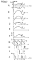
- the low-frequency sound signal S shown in FIG. 2A is composed of two symmetrical waveforms, respectively polarized at a predetermined polarization voltage Vp and at its opposite - Vp.
- This composite low-frequency signal S is desymmetrized in a symmetrical-asymmetrical converter 12 whose output produces the wave form S 2 initially positive, but with a zero bias voltage, as shown in FIG. 2B. Then the signal S 2 is rectified in a rectifier 13 into a signal S 3 shown in FIG.
- the signal S 3 is applied to the input of an integrator 14 having an integration constant of the order of 0.2 to 0.3 s.
- the value of the integration constant is chosen so that it is compatible with the inertia of the needle of a meter, so that the measurement scale is analogous to that of a meter.
- the outgoing signal S 4 from the integrator 14 substantially reproduces the envelope of the low-frequency signal S 2 and is shown in FIG. 2D.
- a linear amplifier 15 amplifies with a predetermined gain the signal S 4 into a signal S 5 shown in FIG. 2E.
- the amplified envelope signal S 5 is then applied to the input of a non-linear amplifier 16 with variable gain relative to predetermined voltage intervals.
- This amplifier is analogous to a blocker sampler according to a logarithmic quantization law. It has a plurality of quantization steps for each of which a voltage applied to the input of the amplifier included in the quantization step is amplified with a portional gain at the lower limit of the quantization step, according to the logarithmic quantization law.
- the outgoing signal S 6 is preferably sampled at the frequency of the periodic reference signal S R , or at a frequency multiple thereof, as shown in FIG. 2 F.
- the comparison circuit 2 comprises two voltage comparators 20 and 21 and a generator 22 which produces the reference signal S R in the form of a sawtooth signal shown in FIG. 2G.
- the first comparator 20 receives respectively at its direct (+) and inverse (-) inputs the sampled envelope signal S 6 and the sawtooth signal S R.
- the peak amplitude V M of the signal S R is chosen so that it is always greater than the amplitude of the signal S 6 .
- the output 23 of the comparator 20 produces a pulse 1 at the instant for which the amplitudes of the signals S 6 and S R are equal.
- the signal S R is a sawtooth signal with voltage decreasing linearly to zero at the end of the period
- the duration t between the pulse and the end of the period is proportional to the amplitude V of the signal S 6 at the instant T - t, as shown in FIG. 2H:
- the second comparator 21 compares the amplitude of the sawtooth reference signal S R delivered by the generator 22 at its inverse input (-) and a reference voltage V o applied by a potentiometer or a variable voltage divider 24 to its direct entry (+).
- the output 25 of the comparator 21 produces a pulse la when there is equal voltages on its inputs, like the comparator 20.
- the so-called reference pulse shown in FIG. 21 is less at the end of each period of duration t o such that:
- V o is chosen so that it indicates the lower threshold for overmodulation of the sound signal of a composite video signal, it appears that, for any pulse I such that t, t o produced on output 23, the signal low-frequency is present and has a suitable amplitude and that, for any pulse such as t> t o , the low-frequency signal presents an undesirable overmodulation.
- the period T of the sawtooth reference signal S R is equal to the period of the frames of a video signal, for example 20 ms.
- the generator 22 receives at its input 20 the frame synchronization signal shown in FIG. 2J.
- an image of the variable pulse I can be viewed on the screen of a video monitor, relative to the still image of the reference pulse l 0 .
- the decoding circuit 3 detects the two lines to which the pulses I and l 0 belong, for each frame.
- the decoding circuit comprises three switches 30, 31, 32, two monostable flip-flops 33 and 34 and an inverter 35. Although the switches are represented diagrammatically by two-position relay contacts in FIG. 1, they are in practice produced by transistors.
- the switches 30 and 31 are put into work by the pulses I delivered by the output 23 of the switch 20.
- the switch 32 is put into work by the reference pulses l 0 delivered by the output 25 of the comparator 21. All the working contacts 30 T , 31 T , and 32 T of the switches are connected to the output of the second monostable flip-flop 34.
- the rest contact 30 R of the switch 30 is connected to the output of flip-flop 34 through the inverter 35.
- the contact movable 31 M of the switch 31 is connected to the movable contact 32 M of the switch 32.
- the movable contact 30 M of the switch 30 and the movable contacts 21 M , 32 M of the switches 21 and 32 are connected respectively to two video inputs 40 and 41 d a color video monitor constituting the display unit 4. These video inputs correspond for example to the green and red cannons.
- the monostable flip-flops 33 and 34 are in series and are respectively sensitive to the rising and falling edges of the pulses they receive.
- the input 36 of the first flip-flop 33 receives the line synchronization signal with period T I , shown in FIG. 2K. It produces a pulse l 1 in response to the rising edge of each line synchronization pulse.
- Each pulse l 1 as shown in FIG. 2L has a predetermined width T 1 so that its falling edge corresponds to the left edge of a vertical bar image B of the screen of the video monitor 4.
- the second flip-flop 34 delivers a pulse 1 2 , as shown in FIG. 2M, towards the working contacts 30 T , 31 T and 32 T and towards the input of the inverter 35.
- Each pulse l 2 has a width T 2 at least equal to the period of the image points so that the vertical bar B has a width at least equal to an image point.
- the amplitude of the low-frequency signal is displayed as follows for each frame. If t ⁇ t o , that is to say if V ⁇ V o , the pulse l 0 of the frame puts switch 32 to work after T - t o succeeding the start of the frame, and the pulse 1 2 corresponding to the so-called reference line defined by l 0 excites the red cannon through the switch 32 at work.
- the pulse l 2 corresponding to the line defined by I excites the red and green canons through switches 30 and 31. Consequently, the image fixed indicating the reference voltage V o is red in the bar B and the variable image indicating the amplitude of the low-frequency signal to be analyzed is yellow and below the red fixed image. It will be noted that, in order to visualize certainly at any place on the bar B the fixed and moving images, the pulses I and 1 0 have a width preferably equal to the line period T 1 , and in general greater than T 1 - T 2 .
- the signal resulting from the inversion of the pulse 1 2 by the inverter 35 is transmitted through the switches 30 and 31 at rest to the video inputs 40 and 41 and directly to the other video input 42 corresponding to the blue.
- the yellow and red image indexes are displayed on a vertical black bar B.
- variable yellow image index representative of the pulse 1 is above the fixed red reference index.
- the color of the variable index can be modified, as soon as the amplitude of the signal S 6 is greater than the threshold V o .
- the variable index can be red above the fixed red index, and yellow below, as before.
- the decoding circuit 3 includes the elements shown in broken lines in FIG. 1 These elements are a monostable flip-flop 37 receiving the pulses 1 which are also transmitted to the control input of switch 32, and an AND gate 38 whose inputs are connected to the output of flip-flop 37 and to output 23 of the comparator 20.
- the switch 30 is only controlled by the pulses leaving the AND gate 38, and the switch 31 is only controlled by the pulses 1 leaving the comparator 20.
- all the monostable flip-flops 33, 34 and 37 may include an adjustable capacitor and / or an adjustable resistor in order to adjust their time constant, that is to say the width of the pulses produced.
- the time constant of the monostable lever 37 is adjusted in proportion to the value V o adjusted by the potentiometer 24.
- the lever 33 determines the location of the vertical bar B on the screen, which is generally chosen near the vertical left or right edge of the screen.
- the flip-flop 34 determines the width of the bar B, practically equal to a few image points.
- a video mixer is inserted in order to view on the screen of the video monitor both the bar B and the video image of a color television program, the sound signal of which is applied to input 10 of the device.
- the shaping circuit 1 is not essential; thus the device can comprise at least one of the following elements connected in series with the input 11 of the first comparator 20 receiving a signal which is a function of the low-frequency signal S, namely a rectifier such as 13, an integrator playing the role of envelope detector such as 14, a linear amplifier such as 15, and a non-linear amplifier with variable gain such as 16.
- the amplifier 16 When it is desired to view the actual amplitude variations of a low-frequency signal, without using a logarithmic scale, the amplifier 16 is deleted; in fact, the logarithmic scale obtained by means of the non-linear amplifier 16 was chosen in order to carry out measurements in decibels, by prior calibration of the height of the vertical bar B on the screen of the video monitor, in analogy with the dial of a conventional meter, which is generally used in broadcasting studios for visual control of the modulation depth of the sound signal.
- the periodic sawtooth reference signal may be of increasing linear voltage
- the video monitor may be a black and white video monitor in which case the movable contacts 30 M , 31 M and 32 M are connected to the input. monitor video.
- the switches and others (not shown) of the decoding circuit 3 can be selected to assign other primary or composite colors than those mentioned above, to the variable and fixed indexes and to the background of the vertical bar B.
Landscapes
- Physics & Mathematics (AREA)
- General Physics & Mathematics (AREA)
- Engineering & Computer Science (AREA)
- Multimedia (AREA)
- Signal Processing (AREA)
- Testing, Inspecting, Measuring Of Stereoscopic Televisions And Televisions (AREA)
Applications Claiming Priority (2)
| Application Number | Priority Date | Filing Date | Title |
|---|---|---|---|
| FR8009159A FR2481458A1 (fr) | 1980-04-23 | 1980-04-23 | Dispositif de mesure et de visualisation de l'amplitude d'un signal basse frequence |
| FR8009159 | 1980-04-23 |
Publications (2)
| Publication Number | Publication Date |
|---|---|
| EP0038726A1 EP0038726A1 (fr) | 1981-10-28 |
| EP0038726B1 true EP0038726B1 (fr) | 1984-05-02 |
Family
ID=9241279
Family Applications (1)
| Application Number | Title | Priority Date | Filing Date |
|---|---|---|---|
| EP19810400300 Expired EP0038726B1 (fr) | 1980-04-23 | 1981-02-26 | Dispositif de mesure et de visualisation de l'amplitude d'un signal basse-fréquence |
Country Status (3)
| Country | Link |
|---|---|
| EP (1) | EP0038726B1 (ref) |
| DE (1) | DE3163347D1 (ref) |
| FR (1) | FR2481458A1 (ref) |
Families Citing this family (1)
| Publication number | Priority date | Publication date | Assignee | Title |
|---|---|---|---|---|
| JPS6022007U (ja) * | 1983-07-21 | 1985-02-15 | ソニー株式会社 | 衛星放送受信用アンテナの方向調整装置 |
Family Cites Families (1)
| Publication number | Priority date | Publication date | Assignee | Title |
|---|---|---|---|---|
| JPS5819882Y2 (ja) * | 1976-11-15 | 1983-04-23 | ソニー株式会社 | テレビジヨン受像機 |
-
1980
- 1980-04-23 FR FR8009159A patent/FR2481458A1/fr active Granted
-
1981
- 1981-02-26 DE DE8181400300T patent/DE3163347D1/de not_active Expired
- 1981-02-26 EP EP19810400300 patent/EP0038726B1/fr not_active Expired
Also Published As
| Publication number | Publication date |
|---|---|
| FR2481458A1 (fr) | 1981-10-30 |
| DE3163347D1 (en) | 1984-06-07 |
| FR2481458B1 (ref) | 1983-02-04 |
| EP0038726A1 (fr) | 1981-10-28 |
Similar Documents
| Publication | Publication Date | Title |
|---|---|---|
| EP0043298B1 (fr) | Système de télévision à haute définition | |
| FR2515459A1 (fr) | Systeme d'affichage de television a artefacts de balayage de ligne reduits | |
| FR2482813A1 (fr) | Dispositif de codage et de signaux d'image et de son | |
| FR2476954A1 (ref) | ||
| FR2536620A1 (fr) | Televiseur numerique avec convertisseur analogique-numerique ayant un gain multiplexe dans le temps | |
| FR2482815A1 (fr) | Dispositif de codage et de decodage de signaux d'image et de son | |
| FR2559329A1 (fr) | Dispositif pour produire, d'un signal de television, un signal d'un rapport d'aspect different | |
| FR2628280A1 (fr) | Appareil de traitement adaptif pour l'etalement d'un signal video | |
| FR2510853A1 (fr) | Systeme de television et moyen transducteur d'image, moyen de visualisation, dispositif pour former un signal video composite et dispositif pour decoder ce signal a y utiliser | |
| FR2593010A1 (fr) | Systeme de traitement d'un signal video brouille | |
| US4170025A (en) | Low contrast measurement apparatus | |
| US5764284A (en) | System and method for measuring the fidelity of video | |
| US5748229A (en) | System and method for evaluating video fidelity by determining information frame rate | |
| FR2607342A1 (fr) | Systeme de traitement de signaux de television s'adaptant au mouvement | |
| FR2679088A1 (fr) | Circuit d'elimination des bruits pour un recepteur de television. | |
| FR2553614A1 (fr) | Televiseur avec affichage auxiliaire sur l'ecran | |
| EP0038726B1 (fr) | Dispositif de mesure et de visualisation de l'amplitude d'un signal basse-fréquence | |
| FR2581495A1 (fr) | Systeme de conditionnement de signaux et systeme de prise d'images l'utilisant | |
| EP0359553B1 (en) | Recursive noise reduction filter for video components | |
| US6310645B1 (en) | Method and apparatus for measuring characteristics of a communication signal modulated with a composite video signal without synchronizing to the signal | |
| FR2608880A1 (fr) | Systeme d'extraction et de mesure d'amplitude des signaux de synchronisation dans les recepteurs-emetteurs de television, en particulier pour transmission par satellite | |
| EP0022405A1 (fr) | Dispositif de numérisation des signaux vidéofréquence de télévision et équipement de transmission comportant un tel dispositif | |
| Rátosi et al. | Measuring camera exposure time using equivalent sampling | |
| FR2513777A1 (fr) | Dispositif de memorisation et de traitement de signaux analogiques en vue de l'affichage d'une image de type oscilloscopique et oscilloscope comprenant un tel dispositif de traitement | |
| JP3606158B2 (ja) | 画質評価装置 |
Legal Events
| Date | Code | Title | Description |
|---|---|---|---|
| PUAI | Public reference made under article 153(3) epc to a published international application that has entered the european phase |
Free format text: ORIGINAL CODE: 0009012 |
|
| AK | Designated contracting states |
Designated state(s): BE CH DE GB IT LI NL SE |
|
| 17P | Request for examination filed |
Effective date: 19811116 |
|
| ITF | It: translation for a ep patent filed | ||
| GRAA | (expected) grant |
Free format text: ORIGINAL CODE: 0009210 |
|
| AK | Designated contracting states |
Designated state(s): BE CH DE GB IT LI NL SE |
|
| REF | Corresponds to: |
Ref document number: 3163347 Country of ref document: DE Date of ref document: 19840607 |
|
| PLBE | No opposition filed within time limit |
Free format text: ORIGINAL CODE: 0009261 |
|
| STAA | Information on the status of an ep patent application or granted ep patent |
Free format text: STATUS: NO OPPOSITION FILED WITHIN TIME LIMIT |
|
| 26N | No opposition filed | ||
| PGFP | Annual fee paid to national office [announced via postgrant information from national office to epo] |
Ref country code: CH Payment date: 19890207 Year of fee payment: 9 |
|
| PGFP | Annual fee paid to national office [announced via postgrant information from national office to epo] |
Ref country code: DE Payment date: 19890208 Year of fee payment: 9 |
|
| PGFP | Annual fee paid to national office [announced via postgrant information from national office to epo] |
Ref country code: SE Payment date: 19890210 Year of fee payment: 9 |
|
| ITTA | It: last paid annual fee | ||
| PGFP | Annual fee paid to national office [announced via postgrant information from national office to epo] |
Ref country code: NL Payment date: 19890228 Year of fee payment: 9 Ref country code: GB Payment date: 19890228 Year of fee payment: 9 |
|
| PGFP | Annual fee paid to national office [announced via postgrant information from national office to epo] |
Ref country code: BE Payment date: 19890303 Year of fee payment: 9 |
|
| PG25 | Lapsed in a contracting state [announced via postgrant information from national office to epo] |
Ref country code: GB Effective date: 19900226 |
|
| PG25 | Lapsed in a contracting state [announced via postgrant information from national office to epo] |
Ref country code: SE Effective date: 19900227 |
|
| PG25 | Lapsed in a contracting state [announced via postgrant information from national office to epo] |
Ref country code: LI Effective date: 19900228 Ref country code: CH Effective date: 19900228 Ref country code: BE Effective date: 19900228 |
|
| BERE | Be: lapsed |
Owner name: ETABLISSEMENT PUBLIC TELEDIFFUSION DE FRANCE Effective date: 19900228 |
|
| PG25 | Lapsed in a contracting state [announced via postgrant information from national office to epo] |
Ref country code: NL Effective date: 19900901 |
|
| NLV4 | Nl: lapsed or anulled due to non-payment of the annual fee | ||
| GBPC | Gb: european patent ceased through non-payment of renewal fee | ||
| REG | Reference to a national code |
Ref country code: CH Ref legal event code: PL |
|
| PG25 | Lapsed in a contracting state [announced via postgrant information from national office to epo] |
Ref country code: DE Effective date: 19901101 |
|
| EUG | Se: european patent has lapsed |
Ref document number: 81400300.0 Effective date: 19901107 |