EP0038612B1 - Modules de séparation à fibres creuses - Google Patents
Modules de séparation à fibres creuses Download PDFInfo
- Publication number
- EP0038612B1 EP0038612B1 EP81200531A EP81200531A EP0038612B1 EP 0038612 B1 EP0038612 B1 EP 0038612B1 EP 81200531 A EP81200531 A EP 81200531A EP 81200531 A EP81200531 A EP 81200531A EP 0038612 B1 EP0038612 B1 EP 0038612B1
- Authority
- EP
- European Patent Office
- Prior art keywords
- zone
- filaments
- rings
- potting compound
- housing
- Prior art date
- Legal status (The legal status is an assumption and is not a legal conclusion. Google has not performed a legal analysis and makes no representation as to the accuracy of the status listed.)
- Expired
Links
- 238000004382 potting Methods 0.000 claims description 22
- 150000001875 compounds Chemical class 0.000 claims description 16
- 239000012530 fluid Substances 0.000 claims description 10
- 238000013022 venting Methods 0.000 claims description 2
- 239000012528 membrane Substances 0.000 description 7
- 239000012466 permeate Substances 0.000 description 7
- 239000007788 liquid Substances 0.000 description 5
- 239000012141 concentrate Substances 0.000 description 4
- 239000000835 fiber Substances 0.000 description 4
- WGFNXGPBPIJYLI-UHFFFAOYSA-N 2,6-difluoro-3-[(3-fluorophenyl)sulfonylamino]-n-(3-methoxy-1h-pyrazolo[3,4-b]pyridin-5-yl)benzamide Chemical compound C1=C2C(OC)=NNC2=NC=C1NC(=O)C(C=1F)=C(F)C=CC=1NS(=O)(=O)C1=CC=CC(F)=C1 WGFNXGPBPIJYLI-UHFFFAOYSA-N 0.000 description 3
- 239000000463 material Substances 0.000 description 3
- 229920000647 polyepoxide Polymers 0.000 description 3
- 238000011045 prefiltration Methods 0.000 description 3
- 238000000926 separation method Methods 0.000 description 3
- 238000004804 winding Methods 0.000 description 3
- 239000003822 epoxy resin Substances 0.000 description 2
- 238000011068 loading method Methods 0.000 description 2
- 238000007789 sealing Methods 0.000 description 2
- 239000004593 Epoxy Substances 0.000 description 1
- 230000004323 axial length Effects 0.000 description 1
- 230000004888 barrier function Effects 0.000 description 1
- 238000005266 casting Methods 0.000 description 1
- 239000002131 composite material Substances 0.000 description 1
- 230000000694 effects Effects 0.000 description 1
- 125000003700 epoxy group Chemical group 0.000 description 1
- 238000001914 filtration Methods 0.000 description 1
- 238000011065 in-situ storage Methods 0.000 description 1
- 238000004519 manufacturing process Methods 0.000 description 1
- 239000011159 matrix material Substances 0.000 description 1
- 239000002184 metal Substances 0.000 description 1
- 239000002245 particle Substances 0.000 description 1
- 238000009931 pascalization Methods 0.000 description 1
- 239000004033 plastic Substances 0.000 description 1
- 230000001681 protective effect Effects 0.000 description 1
- 239000007787 solid Substances 0.000 description 1
- 239000008247 solid mixture Substances 0.000 description 1
- 239000006104 solid solution Substances 0.000 description 1
- 239000000758 substrate Substances 0.000 description 1
- 238000009827 uniform distribution Methods 0.000 description 1
- 238000011144 upstream manufacturing Methods 0.000 description 1
Images
Classifications
-
- B—PERFORMING OPERATIONS; TRANSPORTING
- B01—PHYSICAL OR CHEMICAL PROCESSES OR APPARATUS IN GENERAL
- B01D—SEPARATION
- B01D53/00—Separation of gases or vapours; Recovering vapours of volatile solvents from gases; Chemical or biological purification of waste gases, e.g. engine exhaust gases, smoke, fumes, flue gases, aerosols
- B01D53/22—Separation of gases or vapours; Recovering vapours of volatile solvents from gases; Chemical or biological purification of waste gases, e.g. engine exhaust gases, smoke, fumes, flue gases, aerosols by diffusion
-
- B—PERFORMING OPERATIONS; TRANSPORTING
- B01—PHYSICAL OR CHEMICAL PROCESSES OR APPARATUS IN GENERAL
- B01D—SEPARATION
- B01D63/00—Apparatus in general for separation processes using semi-permeable membranes
- B01D63/02—Hollow fibre modules
- B01D63/024—Hollow fibre modules with a single potted end
-
- B—PERFORMING OPERATIONS; TRANSPORTING
- B01—PHYSICAL OR CHEMICAL PROCESSES OR APPARATUS IN GENERAL
- B01D—SEPARATION
- B01D63/00—Apparatus in general for separation processes using semi-permeable membranes
- B01D63/02—Hollow fibre modules
- B01D63/025—Bobbin units
-
- B—PERFORMING OPERATIONS; TRANSPORTING
- B01—PHYSICAL OR CHEMICAL PROCESSES OR APPARATUS IN GENERAL
- B01D—SEPARATION
- B01D65/00—Accessories or auxiliary operations, in general, for separation processes or apparatus using semi-permeable membranes
- B01D65/10—Testing of membranes or membrane apparatus; Detecting or repairing leaks
- B01D65/104—Detection of leaks in membrane apparatus or modules
-
- B—PERFORMING OPERATIONS; TRANSPORTING
- B01—PHYSICAL OR CHEMICAL PROCESSES OR APPARATUS IN GENERAL
- B01D—SEPARATION
- B01D2313/00—Details relating to membrane modules or apparatus
- B01D2313/06—External membrane module supporting or fixing means
-
- B—PERFORMING OPERATIONS; TRANSPORTING
- B01—PHYSICAL OR CHEMICAL PROCESSES OR APPARATUS IN GENERAL
- B01D—SEPARATION
- B01D2313/00—Details relating to membrane modules or apparatus
- B01D2313/20—Specific housing
-
- B—PERFORMING OPERATIONS; TRANSPORTING
- B01—PHYSICAL OR CHEMICAL PROCESSES OR APPARATUS IN GENERAL
- B01D—SEPARATION
- B01D2313/00—Details relating to membrane modules or apparatus
- B01D2313/20—Specific housing
- B01D2313/201—Closed housing, vessels or containers
- B01D2313/2011—Pressure vessels
Definitions
- membranes are contained in vessels called modules, comprising a container having various inlet and outlet ports and an assembly of membranes within said container.
- the internal configurations of the membranes and of the vessel are so arranged as to permit the introduction of a feed stream under pressure on the upstream faces of the membranes and to include means for collecting permeate which passes through the membranes and emerges on their downstream faces, and means are provided for keeping feed and permeate materials from commingling.
- Membranes have been fabricated in the form of open-ended hollow tubular filaments so arranged and sealed into header plates as to provide a separation of the flow over the extemal surfaces of the hollow filaments from the flows within the bores of the hollow filaments. These devices are called hollow filament separatory modules.
- the present invention provides an improved sealing arrangement which ensures that there is no leakage within the module from the high pressure flow to the low pressure flow in a hollow filament separatory module which includes in combination an annulus of filaments consisting of a plurality of layers of semi-permeable helically wound hollow filaments having open ends and a main portion, a pressure housing enclosing said filaments, a zone, which, when the module is in use, is pressurized, first flow means in said zone for causing fluid to flow in contact with the outer surfaces of said filaments at the main portions thereof, a collection zone of said housing, an outlet from said collection zone to allow fluid to flow from within said hollow filaments through the open ends thereof and through and out of said zone, which in use is pressurised, potting compound encapsulating said hollow filaments between said zone, which in use is pressurised, and said collection zone and first and second O-ring
- US-A-3,442,389 discloses a hollow filament separator module in which a bundle of hollow filaments are enclosed within a pressure housing an seals are provided for sealing a space within the housing in communication with the outside surfaces of the hollow filaments from a further space within the housing which communicates with the insides of the hollow filaments.
- Two seals are each formed by a plug of epoxy resin which is cast in situ in the housing and produces the seal by being bonded directly to the side surfaces of the hollow filaments on the one hand and to the internal surface of the wall of the housing on the other hand.
- US-A-3,422,008 discloses a hollow filament separatory module which includes the combination described above, but here again the seal, which is provided by the two O-rings is not satisfactory. This is because any leakage which may take place past the first 0-ring rapidly builds up a pressure on the second 0- ring which may then itself leak and allow the fluid which flows from within the hollow filaments to become vitiated by the unseparated fluid which flows in contact with the outer surfaces of the filaments.
- the object of this invention is to improve the seal provided by the two O-rings in a module which includes the above combination, so that leakage of the unseparated fluid past the seal into the collection zone is completely prevented.
- such a module is characterised in that said first and second 0-rings separate an intermediate zone around said potting compound from said zone, which in use is pressurised, and said collection zone, and weep hole port means are provided between said first and second O-rings for venting said intermediate zone.
- the housing comprises an enclosure surrounding said annulus, first and second end plates with said enclosure therebetween, first and second shoulders respectively formed on said first and second end plates and bolt means rigidly fixing said end plates to one another with respective ends of said enclosure butting said first and second shoulders.
- the enclosure may comprise a pressure sleeve enclosing said collection zone and a shell surrounding said main portions, a part of said sleeve overlying said shell, said first and second O-rings forming seals between said sleeve and said potting compound.
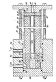
- a module constructed in accordance with this invention is designated in the drawings, generally by the numeral 20.
- the module includes an annulus 22 formed of wound permeable hollow filaments and braid sleeve 26 folded over to sandwich the filaments for the most part between inner and outer sleeve sections 26a and 26b with solid rod 28 projecting within and occupying annulus core 30.
- the specific manner in which the annulus is wound is described in detail below.
- the fibres which are of relatively large diameter are wound in helical fashion with adjacent layers wound in opposite hand. There is relatively uniform distribution of the large diameter fibres and the channel spaces and surfaces of the fibres usable for separation.
- the hollow fibres are 250 micrometres or greater in outside diameter. In certain applications 500 micrometres outside diameter is preferred.
- the preferred embodiment contemplates a composite hollow fibre comprising a porous substrate, overcoated with a selected high filtration rejection barrier.
- the annulus 22 is encased within pressure resistant shell 32 and pressure sleeve 34 between end plates 36 and 38 held in position by stringers 40 passing through holes 42 formed in the end plates.
- Axial feed-in port 44 is provided in end plate 36 to allow the fluid which is being operated upon to wash the outside of the fibres 22 after passing through prefilter 46 and perforated disc 48.
- prefilter 46 and disc 48 can be omitted.
- prefilter 46 is a felt structure through which the liquid can pass and disc 48 is a rigid plastic member.
- the pressure sleeve 34 is provided with radial ports 50 and 52 which respectively provide outlets for permeate and concentrate. Port 54 functions as a weep hole. Suitable 0- rings 56, 58, 60, 62 and 64 are provided. The end of the annulus 22 within pressure sleeve 34 is encased in potting compound 66 as will be described below.
- Collapsible expansible braided sleeve 26 is secured over a suitable winding shaft for a distance greater than the axial length of the annulus to support the inner surface of the annulus. This is the surface immediately upon which the first wraps of the bundle 22 are wound.
- potting compound 66 After winding, one end of annulus 22 is encapsulated in potting compound 66.
- the art of casting fibrous and other materials into a common matrix is well known and referred to as "potting". It is also well known to select potting compounds of which epoxies are but one example, so that their compatibility with fibres or other materials to be encapsulated makes for intimate bonding in the interfaces between the fibres or particles, and the encapsulating compound. Thus, in the case of hollow fibres to be sealed in the potting compound 66 it would be most desirable that the fibre surfaces to wet well by the potting compound in its prepolymerised fluid form.
- the ends of fibres which are cut or exposed to provide exit for the permeate flow are in access surfaces within the potting compound at either a different elevation or a different angle than the surface of the potting compound required to take the pressurising thrust force, or both.
- the permeate collection chamber 75 is sealed apart from the pressurised concentrate region of the potting compound by "O"-rings 56 and 58 with weephole 54 additionally protected by 0-ring seal 60 to allow any leak of concentrate to exit the module assembly without inadvertently commingling with the permeate.
- the pressurised concentrate is removed at port 52 which is sealed by O-rings 60 and 62.
- the O-rings 58 and 60 define an intermediate zone between the collection zone containing the collection chamber 71 and the pressurized zone which is surrounded by the pressure resistant shell 32.
- the pressure shell has been a cylindrical chamber in view of the accepted manner of resisting the high hydrostatic pressures.
- the requirement has been imposed on the shell to accept both the hoop stress loadings and axial loading developed by connections to the end plates.
- the end plates were frequently mounted to the shell and connected by snap rings or the like, which carried the thrust on the end plates to shell surface through grooves or some other connective ridges or the like. This required that the shell be of substantial thickness and mechanical integrity in all directions.
- Stringer bolts 40 secure the two end plates 36 and 38 of the pressure cylinder to one another, thereby eliminating axial stress on the shell.
Claims (5)
Priority Applications (1)
| Application Number | Priority Date | Filing Date | Title |
|---|---|---|---|
| AT81200531T ATE5512T1 (de) | 1978-09-19 | 1979-09-13 | Hohlfasermoduln. |
Applications Claiming Priority (8)
| Application Number | Priority Date | Filing Date | Title |
|---|---|---|---|
| US94373978A | 1978-09-19 | 1978-09-19 | |
| US05/943,793 US4210536A (en) | 1978-09-19 | 1978-09-19 | Hollow filament separatory module |
| US943738 | 1978-09-19 | ||
| US05/943,738 US4207192A (en) | 1978-09-19 | 1978-09-19 | Hollow filament separatory module and method of fabrication |
| US943739 | 1978-09-19 | ||
| US943793 | 1978-09-19 | ||
| US05/956,032 US4220489A (en) | 1978-10-30 | 1978-10-30 | Method of fabricating a hollow filament separator module |
| US956032 | 1978-10-30 |
Related Parent Applications (2)
| Application Number | Title | Priority Date | Filing Date |
|---|---|---|---|
| EP79301885A Division-Into EP0009374B1 (fr) | 1978-09-19 | 1979-09-13 | Procédé de séparation des constituants de mélanges ou solutions gaz-gaz, liquide-liquide ou liquide-solide |
| EP79301885A Division EP0009374B1 (fr) | 1978-09-19 | 1979-09-13 | Procédé de séparation des constituants de mélanges ou solutions gaz-gaz, liquide-liquide ou liquide-solide |
Publications (3)
| Publication Number | Publication Date |
|---|---|
| EP0038612A2 EP0038612A2 (fr) | 1981-10-28 |
| EP0038612A3 EP0038612A3 (en) | 1981-11-25 |
| EP0038612B1 true EP0038612B1 (fr) | 1983-12-07 |
Family
ID=27506027
Family Applications (3)
| Application Number | Title | Priority Date | Filing Date |
|---|---|---|---|
| EP79301885A Expired EP0009374B1 (fr) | 1978-09-19 | 1979-09-13 | Procédé de séparation des constituants de mélanges ou solutions gaz-gaz, liquide-liquide ou liquide-solide |
| EP81200530A Expired EP0038611B1 (fr) | 1978-09-19 | 1979-09-13 | Modules de séparation à fibres creuses et procédés pour la fabrication de ces modules |
| EP81200531A Expired EP0038612B1 (fr) | 1978-09-19 | 1979-09-13 | Modules de séparation à fibres creuses |
Family Applications Before (2)
| Application Number | Title | Priority Date | Filing Date |
|---|---|---|---|
| EP79301885A Expired EP0009374B1 (fr) | 1978-09-19 | 1979-09-13 | Procédé de séparation des constituants de mélanges ou solutions gaz-gaz, liquide-liquide ou liquide-solide |
| EP81200530A Expired EP0038611B1 (fr) | 1978-09-19 | 1979-09-13 | Modules de séparation à fibres creuses et procédés pour la fabrication de ces modules |
Country Status (9)
| Country | Link |
|---|---|
| EP (3) | EP0009374B1 (fr) |
| JP (1) | JPH022835A (fr) |
| CA (1) | CA1154692A (fr) |
| DE (1) | DE2967006D1 (fr) |
| FI (1) | FI792855A (fr) |
| IL (2) | IL58247A (fr) |
| MX (1) | MX155500A (fr) |
| NO (3) | NO151448C (fr) |
| SE (1) | SE447633B (fr) |
Cited By (8)
| Publication number | Priority date | Publication date | Assignee | Title |
|---|---|---|---|---|
| WO2014004645A1 (fr) * | 2012-06-28 | 2014-01-03 | Siemens Industry, Inc. | Procédé d'empotage |
| US9630147B2 (en) | 2010-09-24 | 2017-04-25 | Evoqua Water Technologies Llc | Fluid control manifold for membrane filtration system |
| US9764288B2 (en) | 2007-04-04 | 2017-09-19 | Evoqua Water Technologies Llc | Membrane module protection |
| US9764289B2 (en) | 2012-09-26 | 2017-09-19 | Evoqua Water Technologies Llc | Membrane securement device |
| US9815027B2 (en) | 2012-09-27 | 2017-11-14 | Evoqua Water Technologies Llc | Gas scouring apparatus for immersed membranes |
| US9914097B2 (en) | 2010-04-30 | 2018-03-13 | Evoqua Water Technologies Llc | Fluid flow distribution device |
| US9925499B2 (en) | 2011-09-30 | 2018-03-27 | Evoqua Water Technologies Llc | Isolation valve with seal for end cap of a filtration system |
| US11173453B2 (en) | 2013-10-02 | 2021-11-16 | Rohm And Haas Electronic Materials Singapores | Method and device for repairing a membrane filtration module |
Families Citing this family (15)
| Publication number | Priority date | Publication date | Assignee | Title |
|---|---|---|---|---|
| DE3127282A1 (de) * | 1981-07-10 | 1983-01-27 | Akzo Gmbh, 5600 Wuppertal | Vorrichtung zur waerme- und stoffuebertragung mittels hohlfasern |
| DE3032417C2 (de) * | 1980-08-28 | 1985-08-14 | Akzo Gmbh, 5600 Wuppertal | Vorrichtung zur Wärme- und Stoffübertragung mittels Hohlfasern |
| EP0098823A1 (fr) * | 1982-06-11 | 1984-01-18 | Monsanto Company | Procédé de séparation de gaz par membrane |
| CA1221645A (fr) * | 1983-02-28 | 1987-05-12 | Yoshihiro Okano | Dispositif de filtration a membrane faite de fibres creuses |
| US4572446A (en) * | 1984-03-23 | 1986-02-25 | Omnis Surgical Inc. | Process for making a fiber bundle |
| US4881955A (en) * | 1988-09-12 | 1989-11-21 | Union Carbide Corporation | Method for gas separation using helically wound hollow fibers permeable membrane cartridge |
| US5026479A (en) * | 1990-02-13 | 1991-06-25 | Union Carbide Industrial Gases Technology Corporation | Fluid separation device |
| US5430041A (en) * | 1991-05-10 | 1995-07-04 | Hoffmann-La Roche Inc. | Amino acid derivatives having antiviral activity |
| FI114617B (fi) * | 1999-07-09 | 2004-11-30 | Steris Europe Inc | Suodatinyksikkö ja menetelmä sen tiivistämiseksi |
| NL1013465C2 (nl) | 1999-11-02 | 2001-05-03 | Stork Friesland Bv | Membraanfiltratie-element met hulselement en moforganen. |
| JP4631608B2 (ja) * | 2005-08-29 | 2011-02-16 | Nok株式会社 | 中空糸膜モジュール及びその製造方法 |
| JP5075772B2 (ja) * | 2008-09-12 | 2012-11-21 | 三菱レイヨン株式会社 | 中空糸膜モジュールの製造方法 |
| CN103153427B (zh) * | 2010-09-28 | 2015-09-30 | 赛尔格有限责任公司 | 液体脱气薄膜接触器、元件、系统及相关方法 |
| US10322375B2 (en) | 2015-07-14 | 2019-06-18 | Evoqua Water Technologies Llc | Aeration device for filtration system |
| WO2018134404A1 (fr) | 2017-01-20 | 2018-07-26 | Albert Sturm | Produit d'entretien pour lentilles de contact |
Family Cites Families (11)
| Publication number | Priority date | Publication date | Assignee | Title |
|---|---|---|---|---|
| US3422008A (en) * | 1963-10-24 | 1969-01-14 | Dow Chemical Co | Wound hollow fiber permeability apparatus and process of making the same |
| US3455460A (en) * | 1967-02-13 | 1969-07-15 | Dow Chemical Co | Permeability separatory apparatus and processes of making and using the same |
| US3442389A (en) * | 1967-04-17 | 1969-05-06 | Morris Mendelson | Desalinization apparatus |
| GB1380393A (en) * | 1971-03-26 | 1975-01-15 | Ici Ltd | Sealing fibres into gaps |
| US3734989A (en) * | 1971-08-13 | 1973-05-22 | Us Interior | Fiber bundle assembly |
| FR2193633A1 (en) * | 1972-07-26 | 1974-02-22 | Rhone Poulenc Sa | Membrane sepn cell - for fractionating fluids by dialysis, (reverse) osmosis, ultrafiltration etc |
| JPS5221326Y2 (fr) * | 1972-08-24 | 1977-05-16 | ||
| US4045851A (en) * | 1974-09-20 | 1977-09-06 | Albany International Corporation | Method of fabrication of hollow filament separatory module |
| US4105731A (en) * | 1975-05-02 | 1978-08-08 | Nippon Zeon Co., Ltd. | Method of embedding an end of a bundle of thread-like bodies in a molding material and controlling capillary action by said material |
| FR2361452A1 (fr) * | 1976-08-10 | 1978-03-10 | Rhone Poulenc Ind | Collage de fibres creuses |
| US4061574A (en) * | 1977-02-14 | 1977-12-06 | The Dow Chemical Company | Assembly of permeable hollow fibers and a tubesheet supportable at its face and opened by bores parallel thereto |
-
1979
- 1979-09-12 SE SE7907563A patent/SE447633B/sv not_active IP Right Cessation
- 1979-09-13 EP EP79301885A patent/EP0009374B1/fr not_active Expired
- 1979-09-13 DE DE7979301885T patent/DE2967006D1/de not_active Expired
- 1979-09-13 FI FI792855A patent/FI792855A/fi not_active Application Discontinuation
- 1979-09-13 EP EP81200530A patent/EP0038611B1/fr not_active Expired
- 1979-09-13 EP EP81200531A patent/EP0038612B1/fr not_active Expired
- 1979-09-13 NO NO792972A patent/NO151448C/no unknown
- 1979-09-14 IL IL58247A patent/IL58247A/xx unknown
- 1979-09-14 IL IL68847A patent/IL68847A/xx unknown
- 1979-09-18 MX MX79179315A patent/MX155500A/es unknown
- 1979-09-19 CA CA000335910A patent/CA1154692A/fr not_active Expired
-
1983
- 1983-06-15 NO NO832172A patent/NO153122C/no unknown
- 1983-06-15 NO NO832171A patent/NO153360C/no unknown
-
1989
- 1989-03-15 JP JP1061100A patent/JPH022835A/ja active Granted
Cited By (10)
| Publication number | Priority date | Publication date | Assignee | Title |
|---|---|---|---|---|
| US9764288B2 (en) | 2007-04-04 | 2017-09-19 | Evoqua Water Technologies Llc | Membrane module protection |
| US9914097B2 (en) | 2010-04-30 | 2018-03-13 | Evoqua Water Technologies Llc | Fluid flow distribution device |
| US9630147B2 (en) | 2010-09-24 | 2017-04-25 | Evoqua Water Technologies Llc | Fluid control manifold for membrane filtration system |
| US9925499B2 (en) | 2011-09-30 | 2018-03-27 | Evoqua Water Technologies Llc | Isolation valve with seal for end cap of a filtration system |
| WO2014004645A1 (fr) * | 2012-06-28 | 2014-01-03 | Siemens Industry, Inc. | Procédé d'empotage |
| US20150136687A1 (en) * | 2012-06-28 | 2015-05-21 | Evoqua Water Technologies Llc | Potting Method |
| US9533261B2 (en) * | 2012-06-28 | 2017-01-03 | Evoqua Water Technologies Llc | Potting method |
| US9764289B2 (en) | 2012-09-26 | 2017-09-19 | Evoqua Water Technologies Llc | Membrane securement device |
| US9815027B2 (en) | 2012-09-27 | 2017-11-14 | Evoqua Water Technologies Llc | Gas scouring apparatus for immersed membranes |
| US11173453B2 (en) | 2013-10-02 | 2021-11-16 | Rohm And Haas Electronic Materials Singapores | Method and device for repairing a membrane filtration module |
Also Published As
| Publication number | Publication date |
|---|---|
| NO792972L (no) | 1980-03-20 |
| EP0009374B1 (fr) | 1984-05-23 |
| NO151448B (no) | 1985-01-02 |
| NO832171L (no) | 1980-03-20 |
| JPH0312928B2 (fr) | 1991-02-21 |
| EP0009374A3 (en) | 1980-12-10 |
| NO153360B (no) | 1985-11-25 |
| SE447633B (sv) | 1986-12-01 |
| NO153360C (no) | 1986-03-05 |
| FI792855A (fi) | 1980-03-20 |
| JPH022835A (ja) | 1990-01-08 |
| EP0038612A2 (fr) | 1981-10-28 |
| IL58247A0 (en) | 1979-12-30 |
| IL58247A (en) | 1986-02-28 |
| EP0038611B1 (fr) | 1983-12-07 |
| MX155500A (es) | 1988-01-25 |
| NO151448C (no) | 1985-04-10 |
| NO832172L (no) | 1980-03-20 |
| DE2967006D1 (en) | 1984-06-28 |
| CA1154692A (fr) | 1983-10-04 |
| IL68847A (en) | 1986-12-31 |
| NO153122C (no) | 1986-01-22 |
| EP0038611A2 (fr) | 1981-10-28 |
| NO153122B (no) | 1985-10-14 |
| EP0009374A2 (fr) | 1980-04-02 |
| EP0038612A3 (en) | 1981-11-25 |
| SE7907563L (sv) | 1980-03-20 |
| EP0038611A3 (en) | 1981-11-25 |
Similar Documents
| Publication | Publication Date | Title |
|---|---|---|
| EP0038612B1 (fr) | Modules de séparation à fibres creuses | |
| US5160042A (en) | Double ended hollow fiber bundle and fluids separation apparatus | |
| US4207192A (en) | Hollow filament separatory module and method of fabrication | |
| US4061574A (en) | Assembly of permeable hollow fibers and a tubesheet supportable at its face and opened by bores parallel thereto | |
| US4352736A (en) | Wound flattened hollow fiber assembly having plural spaced core sections | |
| RU2042409C1 (ru) | Сепарационный модуль | |
| EP0454918B1 (fr) | Module de séparation à fibres creuses et méthode pour son utilisation | |
| US4865736A (en) | Hollow fiber separatory module with encased fiber bundle | |
| US5071552A (en) | Multiple bundle fluid separation apparatus | |
| US5460720A (en) | Pleated membrane crossflow fluid separation device | |
| EP0234893B1 (fr) | Plaque tubulaire pour appareil de perméation à fibres creuses enroulées en spirale | |
| GB1566364A (en) | Hollow fibre permeator | |
| US4632756A (en) | Multiple bundle separatory module | |
| US4210536A (en) | Hollow filament separatory module | |
| US3494465A (en) | Selectively permeable membrane separation apparatus | |
| KR20180034609A (ko) | 유체들의 분리를 위한 유연하게 조정가능한 막 카트리지들 | |
| EP0226431B1 (fr) | Module de séparation à fibres creuses | |
| EP0228836A2 (fr) | Carter à extrémité filetée | |
| CA1321549C (fr) | Module a membrane tubulaire | |
| RU2595699C1 (ru) | Мембранный газоразделительный модуль | |
| US4578190A (en) | Fluid distribution system for separation modules | |
| US4565630A (en) | Fluid distribution system for separation modules | |
| EP0103953B1 (fr) | Module de séparation comprenant des membranes de fibre creuse | |
| EP0060157A2 (fr) | Boîtier à haute pression | |
| JP3596980B2 (ja) | 流体分離装置 |
Legal Events
| Date | Code | Title | Description |
|---|---|---|---|
| PUAI | Public reference made under article 153(3) epc to a published international application that has entered the european phase |
Free format text: ORIGINAL CODE: 0009012 |
|
| PUAL | Search report despatched |
Free format text: ORIGINAL CODE: 0009013 |
|
| 17P | Request for examination filed |
Effective date: 19810529 |
|
| AC | Divisional application: reference to earlier application |
Ref document number: 9374 Country of ref document: EP |
|
| AK | Designated contracting states |
Designated state(s): AT BE CH DE FR GB IT LU NL |
|
| AK | Designated contracting states |
Designated state(s): AT BE CH DE FR GB IT LU NL |
|
| RAP1 | Party data changed (applicant data changed or rights of an application transferred) |
Owner name: ALBANY INTERNATIONAL CORP. |
|
| ITF | It: translation for a ep patent filed |
Owner name: JACOBACCI & PERANI S.P.A. |
|
| GRAA | (expected) grant |
Free format text: ORIGINAL CODE: 0009210 |
|
| AC | Divisional application: reference to earlier application |
Ref document number: 9374 Country of ref document: EP |
|
| AK | Designated contracting states |
Designated state(s): AT BE CH DE FR GB IT LU NL |
|
| REF | Corresponds to: |
Ref document number: 5512 Country of ref document: AT Date of ref document: 19831215 Kind code of ref document: T |
|
| REF | Corresponds to: |
Ref document number: 2966483 Country of ref document: DE Date of ref document: 19840112 |
|
| ET | Fr: translation filed | ||
| PLBE | No opposition filed within time limit |
Free format text: ORIGINAL CODE: 0009261 |
|
| STAA | Information on the status of an ep patent application or granted ep patent |
Free format text: STATUS: NO OPPOSITION FILED WITHIN TIME LIMIT |
|
| 26N | No opposition filed | ||
| ITTA | It: last paid annual fee | ||
| EPTA | Lu: last paid annual fee | ||
| PGFP | Annual fee paid to national office [announced via postgrant information from national office to epo] |
Ref country code: GB Payment date: 19970904 Year of fee payment: 19 |
|
| PGFP | Annual fee paid to national office [announced via postgrant information from national office to epo] |
Ref country code: FR Payment date: 19970909 Year of fee payment: 19 |
|
| PGFP | Annual fee paid to national office [announced via postgrant information from national office to epo] |
Ref country code: LU Payment date: 19970911 Year of fee payment: 19 |
|
| PGFP | Annual fee paid to national office [announced via postgrant information from national office to epo] |
Ref country code: AT Payment date: 19970912 Year of fee payment: 19 |
|
| PGFP | Annual fee paid to national office [announced via postgrant information from national office to epo] |
Ref country code: DE Payment date: 19970919 Year of fee payment: 19 |
|
| PGFP | Annual fee paid to national office [announced via postgrant information from national office to epo] |
Ref country code: CH Payment date: 19970925 Year of fee payment: 19 |
|
| PGFP | Annual fee paid to national office [announced via postgrant information from national office to epo] |
Ref country code: NL Payment date: 19970929 Year of fee payment: 19 |
|
| PGFP | Annual fee paid to national office [announced via postgrant information from national office to epo] |
Ref country code: BE Payment date: 19971104 Year of fee payment: 19 |
|
| PG25 | Lapsed in a contracting state [announced via postgrant information from national office to epo] |
Ref country code: LU Free format text: LAPSE BECAUSE OF NON-PAYMENT OF DUE FEES Effective date: 19980913 Ref country code: GB Free format text: LAPSE BECAUSE OF NON-PAYMENT OF DUE FEES Effective date: 19980913 Ref country code: AT Free format text: LAPSE BECAUSE OF NON-PAYMENT OF DUE FEES Effective date: 19980913 |
|
| PG25 | Lapsed in a contracting state [announced via postgrant information from national office to epo] |
Ref country code: CH Free format text: LAPSE BECAUSE OF NON-PAYMENT OF DUE FEES Effective date: 19980930 Ref country code: BE Free format text: LAPSE BECAUSE OF NON-PAYMENT OF DUE FEES Effective date: 19980930 |
|
| BERE | Be: lapsed |
Owner name: ALBANY INTERNATIONAL CORP. Effective date: 19980930 |
|
| PG25 | Lapsed in a contracting state [announced via postgrant information from national office to epo] |
Ref country code: NL Free format text: LAPSE BECAUSE OF NON-PAYMENT OF DUE FEES Effective date: 19990401 |
|
| GBPC | Gb: european patent ceased through non-payment of renewal fee |
Effective date: 19980913 |
|
| REG | Reference to a national code |
Ref country code: CH Ref legal event code: PL |
|
| PG25 | Lapsed in a contracting state [announced via postgrant information from national office to epo] |
Ref country code: FR Free format text: LAPSE BECAUSE OF NON-PAYMENT OF DUE FEES Effective date: 19990531 |
|
| NLV4 | Nl: lapsed or anulled due to non-payment of the annual fee |
Effective date: 19990401 |
|
| PG25 | Lapsed in a contracting state [announced via postgrant information from national office to epo] |
Ref country code: DE Free format text: LAPSE BECAUSE OF NON-PAYMENT OF DUE FEES Effective date: 19990701 |
|
| REG | Reference to a national code |
Ref country code: FR Ref legal event code: ST |