EP0038611A2 - Hohlfasermoduln und Verfahren zu deren Herstellung - Google Patents
Hohlfasermoduln und Verfahren zu deren Herstellung Download PDFInfo
- Publication number
- EP0038611A2 EP0038611A2 EP81200530A EP81200530A EP0038611A2 EP 0038611 A2 EP0038611 A2 EP 0038611A2 EP 81200530 A EP81200530 A EP 81200530A EP 81200530 A EP81200530 A EP 81200530A EP 0038611 A2 EP0038611 A2 EP 0038611A2
- Authority
- EP
- European Patent Office
- Prior art keywords
- potting compound
- filaments
- bundle
- winding
- compound
- Prior art date
- Legal status (The legal status is an assumption and is not a legal conclusion. Google has not performed a legal analysis and makes no representation as to the accuracy of the status listed.)
- Granted
Links
Images


Classifications
-
- B—PERFORMING OPERATIONS; TRANSPORTING
- B01—PHYSICAL OR CHEMICAL PROCESSES OR APPARATUS IN GENERAL
- B01D—SEPARATION
- B01D53/00—Separation of gases or vapours; Recovering vapours of volatile solvents from gases; Chemical or biological purification of waste gases, e.g. engine exhaust gases, smoke, fumes, flue gases, aerosols
- B01D53/22—Separation of gases or vapours; Recovering vapours of volatile solvents from gases; Chemical or biological purification of waste gases, e.g. engine exhaust gases, smoke, fumes, flue gases, aerosols by diffusion
-
- B—PERFORMING OPERATIONS; TRANSPORTING
- B01—PHYSICAL OR CHEMICAL PROCESSES OR APPARATUS IN GENERAL
- B01D—SEPARATION
- B01D63/00—Apparatus in general for separation processes using semi-permeable membranes
- B01D63/02—Hollow fibre modules
- B01D63/024—Hollow fibre modules with a single potted end
-
- B—PERFORMING OPERATIONS; TRANSPORTING
- B01—PHYSICAL OR CHEMICAL PROCESSES OR APPARATUS IN GENERAL
- B01D—SEPARATION
- B01D63/00—Apparatus in general for separation processes using semi-permeable membranes
- B01D63/02—Hollow fibre modules
- B01D63/025—Bobbin units
-
- B—PERFORMING OPERATIONS; TRANSPORTING
- B01—PHYSICAL OR CHEMICAL PROCESSES OR APPARATUS IN GENERAL
- B01D—SEPARATION
- B01D65/00—Accessories or auxiliary operations, in general, for separation processes or apparatus using semi-permeable membranes
- B01D65/10—Testing of membranes or membrane apparatus; Detecting or repairing leaks
- B01D65/104—Detection of leaks in membrane apparatus or modules
-
- B—PERFORMING OPERATIONS; TRANSPORTING
- B01—PHYSICAL OR CHEMICAL PROCESSES OR APPARATUS IN GENERAL
- B01D—SEPARATION
- B01D2313/00—Details relating to membrane modules or apparatus
- B01D2313/06—External membrane module supporting or fixing means
-
- B—PERFORMING OPERATIONS; TRANSPORTING
- B01—PHYSICAL OR CHEMICAL PROCESSES OR APPARATUS IN GENERAL
- B01D—SEPARATION
- B01D2313/00—Details relating to membrane modules or apparatus
- B01D2313/20—Specific housing
- B01D2313/201—Closed housing, vessels or containers
- B01D2313/2011—Pressure vessels
Definitions
- membranes are contained in vessels called modules, comprising a container having various inlet and outlet ports and an assembly of membranes within said container.
- the internal configurations of the membranes and of the vessel are so arranged as to permit the introduction of a feed stream with or without pressure on the upstream faces of the membranes and to include means for collecting permeate which passes through the membranes and emerges on their downstream faces, and means are provided for keeping feed and permeate materials from commingling.
- Membranes have been fabricated in the form of open-ended hollow tubular filaments so arranged and sealed into header plates as to provide a separation of the flow over the external surfaces of the hollow filaments from the flows within the bores of the hollow filaments.
- the filaments or fibres may be used of diameters consistent with the flow requirements of high flux membranes. For example, it is possible to use filaments or fibres with diameters of as little as 100 microns or as much as 500 microns or more. The specific dimensions of length and diameter of the fibres can be very important, depending upon the intended use of the module. In reverse osmosis applications, we prefer fibres of at least about 250 microns in diameter. Additionally, by winding the fibres in a helical fashion with adjacent layers wound to opposite hands there is provided more uniform distribution of the channel spaces and surfaces of the fibres usable for separation.
- the hollow fibres to have diameters of 250 microns or more. Indeed, in some cases we have made very successful use of fibres of over 500 microns in outside diameter.
- a composite hollow fibre comprising a porous substrate, overcoated with a selected high filtration rejection barrier.
- the object of the module of this invention is to overcome deficiencies in prior hollow fine fibre module constructions.
- a hollow filament separatory module comprises in combination a bundle of filaments consisting of a plurality of layers of semi-permeable hollow filaments, each layer being disposed in a helix, a pressure resistant enclosure enclosing the bundle, first and second end plates at the ends of the enclosure, the filament having open ends and main portions, means for isolating the open ends from the main portions, first flow means for causing fluid to flow in contact with the outer surfaces of said filaments at the main portions thereof, second flow means for causing fluid to flow within the hollow filaments and through the open ends thereof, the second flow means including a potting compound encasing the open ends of the filaments, a collection chamber adjacent the potting compound and an access surface formed on said potting compound wherein said open ends of said filaments appear, the sum total area of the access surface when projected upon a plane perpendicular to the direction of internal pressure forces against the potting compound being less than 50% of the area of the cross section of the non-access portions of the potting compound parallel to said plane.
- This construction has the advantages firstly that the module internal pressure acting against the filament potting compound is resisted by a surface of the potting compound in which no cut filament or fibre ends appear. Secondly, the surface of the potting compound which supports the thrust developed by the internal hydraulic pressure may be at right angles to the principal axis of the module (i.e. generally parallel to the surface of the potting compound which faces inwards towards the pressurised region of the module). Thirdly, cut ends of fibres which form outlets for the permeate flow may be located in access surfaces within the potting compound at a different elevation from and or at an angle to the surface of the potting compound required to take the pressure thrust.
- the present invention also consists, according to another of its aspects, in a method of making a module in accordance with the invention comprising winding the hollow filaments to produce the bundle and, after winding, encapsulating one end of the bundle in a potting compound and cutting filaments within the compound to produce filament ends while removing portions of the compound to expose the cut filament ends to provide access to the filament bores, wherein, during the winding of the filaments, a continuous deposit of adhesive is made at generally the same axial position in the bundle so that upon completion of the winding of the bundle there exists within it a barrier of the adhesive separating the portion of the filaments which are subsequently embedded in the compound from the remainder of their lengths thereby impeding undesirable migration of uncured potting compound by capillarity among the filaments during the encapsulation.
- the annular bundle of filaments is self-supporting.
- helical bundles these are generally firmly and permanently associated with a winding shaft or tube originally comprising the mandrel surface.
- a collapsible and expansible sleeve as the surface immediately upon which the first wraps of the bundle are wound.
- This sleeve may be a braided tube of yarn, for example. Said sleeve is secured over the winding shaft for a distance greater than the axial length of the annulus for support of the inner surface of the annulus.
- An additional length of the expansible sleeve sufficient to provide a continuous protective surface for the external fibres of the annulus, rolled around one end of the annulus, may . also be carried on the winding shaft.
- a zone of the sleeve has the adhesive applied thereto so that migration of the potting compound in the sleeve is obstructed in the same axial position as it is impeded among the filaments.
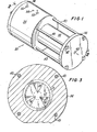
- a module constructed in accordance with this invention is designated in the drawings, generally by the numeral 20.
- the module in completed form is seen in Figures 1 to 5 and includes an annulus 22 formed of wound permeable hollow filaments and braid sleeve 26 folded over to sandwich the filaments for the most part between inner and outer sleeve sections 26a and 26b with solid rod 28 projecting within and occupying annulus core 30.
- the specific manner in which the annulus is wound is described in detail below.
- the fibres which are of relatively large diameter are wound in helical fashion with adjacent layers wound in opposite hand. There is relatively uniform distribution of the large diameter fibres and the channel spaces and surfaces of the fibres usable for separation.
- the hollow fibres are 250 microns or greater in outside diameter. In certain applications 500 microns outside diameter is preferred.
- the preferred embodiment contemplates a composite hollow fibre comprising a porous substrate, overcoated with a selected high filtration rejection barrier.
- the annulus 22 is encased within pressure resistant shell 32 and pressure sleeve 34 between end plates 36 and 38 held in position by stringers 46 passing through holes 42 formed in the end plates.
- Axial feed-in port 44 is provided in end plate 36 to allow the fluid which is being operated upon to wash the outside of the fibres 22 after passing through prefilter 46 and perforated disc 48.
- prefilter 46 and disc 48 can be omitted.
- prefilter 46 is a felt structure through which the liquid can pass and disc 48 is a rigid plastic member.
- the pressure sleeve 34 is provided with radial ports 50 and 52 which respectively provide outlets for permeate and concentrate. Port 54 functions as a weep hole.- Suitable 0-rings 56, 58, 60, 62 and 64 are provided. The end of the annulus 22 within pressure sleeve 34 is encased in potting compound 66 as will be described below.
- the hollow fibres are wound continuously in alternating helices starting on a small diameter shaft, building an annular bundle.
- the path length of fibre forming a helix from one end of the bundle to the other is a function of the radial position of the fibre in the annulus and its helix angle. Therefore, unless appropriate adjustments are made in the relative speed of rotation of the winding shaft and the end-to-end traverse speed of the bundle of filaments during the winding, there will be a continuously increasing length of fibre in any pass between the two ends of the bundle as the radial position increases.
- a series of discrete ratios of the winding and traverse rates is selected and changed from one ratio to the next during the landing at predetermined annular positions thus avoiding the building up of hills and valleys.
- the first layer of helical winding by way of example is indicated by the numeral 23, a second by the numeral 24 and a third by the numeral 25, there being adjacent intermediate unindicated windings wound in opposite hand.
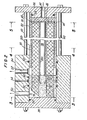
- potting compound 66 After winding, one end of annulus 22 is encapsulated in potting compound 66.
- the art of casting fibrous and other materials into a common matrix is well known and referred to as "potting". It is also well known to select potting compounds of which epoxies are but one example, so that their compatibility with fibres or other materials to be encapsulated makes for intimate bonding in the interfaces between the fibres or particles, and the encapsulating compound. Thus, in the case of hollow fibres to be sealed in the potting compound 66 it would be most desirable that the fibre surfaces be wet well by the potting compound in its prepolymerised fluid form..
- a ring of rubbery cement as indicated in Figure 15 by the numeral 70 is applied to the extensible sleeve member on the winding shaft 68 during the winding operation at a position that will correspond ultimately to the upper regions 72 of the potting compound 66 when it is later placed in mould 74 as shown in Figure 5. Then during the winding of the fibres on first the extensible sleeve and subsequently on top of the preceeding fibre wraps as shown in Figures 10-13, a continuous deposit of the same rubbery cement is made at generally the same axial position in the annulus.
- a substantially doughnut or 0-ring barrier membrane of the rubbery cement in the plane generally designated by numeral 70 in Figure 15 , separating the portion of the fibres which will ultimately become imbedded in the potting compound from the remainder of their lengths.
- the end of inner extensible sleeve member 26a also has the barrier membrane, applied thereto, so that'if it too has a capability for inducing capillary migration of the precured potting compound, said capillarity would be obstructed at the same axial point of position.
- the completion of the potting operation after winding is illustrated in Figure 15 with the mould and potting compound designated respectively by the numerals 74 and 66.
- the uncured potting compound 66 in mould 74 is subject to vibration from subsonic to ultrasonic frequencies by a suitable impulsing device, such as a vibrating hammer or ultrasonic transducer, not shown.
- the fibre bundle 22 is immersed into the mould 74 containing the precured potting compound 66 which, under the urging of the vibratory energy supplied to the mould; tends to migrate within and fill the interstices of the bundle with much greater ease than would have been secured by gravity alone.
- a feature of the subject invention is iDprovide that the internal pressure force developed in the module during use and acting against the fibre potting compound 66 is resisted by a surface of the potting 66 in which no fibres end.
- the numeral 67 in Figure 2 designates this surface. Additionally the surface 67 of the potting supports the thrust developed by the internal hydraulic pressure acting against the inwardly facing surface of the potting.
- ends of fibres which are cut or exposed to provide exit for the permeate flow are in access surfaces within the potting compound at either a different elevation or a different angle than the surface of the potting compound required to take the pressurising thrust force, or both.
- the three v-shaped slices comprise six access surfaces, 79, lying at an oblique angle to the base of the potting compound. These access surface planes resulting from the cutting communicate with the annular gallery within the low pressure region of the assembled module, providing thereby ready access to the permeate collection system.
- the creation of the planes by cutting of the potting compound is accomplished in the preferred embodiment at a time in the curing cycle of the potting compound prior to its final cure.
- the potting compound achieves a state in which it is readily cut without creation of unwanted detritus to block the fibre openings yet of sufficient resilient integrity to slice cleanly by means of a sharp-edged blade.
- cure of the potting compound is completed by heat and /or the passage of time.
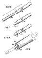
- FIG. 16 An alternate embodiment of the invention directed toward the creation of cut fibre ends in an access surface plane of the potting compound is shown in Figure 16.
- -the fibre helix bundle is wound in such a way that at one end the helix wrapping takes a continuously increasingly steeper angle, forming a conical taper inner surface over a distance indicated by the bracketed length marked "80" in Figurel6.
- this conically tapered end of the annular array of fibres is potted in a mould, it is mounted along with a stepped plug 81, in such a way that the potting compound encapsulates concurrently the end of the fibre bundle and the plug.
- a narrow annular access surface, 79 is machined into the potting compound at an elevation above the support surface provided by the plug.
- FIG. 17 Still another embodiment of our invention is illustrated by Figure 17.
- a wound bundle of filaments is prepared having loops at one end extending at right angles to the main axis of the bundle. This can be accomplished, for example, by mounting on the winding mandrel a thin, disclike member several inches larger in diameter than the mandrel.
- the traverse of the yarn is carried axially beyond said disc so that there is a section of yarn from each loop of the wind that passes over the extreme edge of the disc before the yarn direction is reversed.
- the result of such a winding process is to provide at one end of the helically wound bundle a flange-like circular array of fibres whose axes at that point lie generally at right angles to the annulus axis.
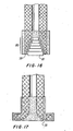
- the mould for such an assemblage provides means for creating segments in the potting compound with fibres of the flange-like bundle extension lying in said segments of potting compound.
- After the full cure' of said potting compound it is possible to create open fibre ends in the fibre lengths lying at right angles to the main axis of the annulus by shearing off the segmented zones of potting compound in which the flange-like array of fibres has been embedded.
- an access plane 79 will be created where each such segmented zone of potting compound has been fractured from the body of the pot. Open ends of fibres will again be found in planes lying at some angle, generally at a right angle, to the surface against which the thrust on the potting compound is applied during module operation.
- Another feature of the subject invention concerns the sealing of the pressurised concentrate regions of the module separate from the permeate collection regions of the module.
- the permeate collection chamber 75 is sealed apart from the pressurised concentrate region of the potting compound by "0"-rings 56 and 58 with weephole 54 additionally protected by 0-ring seal 60 to allow any leak of concentrate to exit the module assembly without inadvertently commingling with the permeate.
- the pressurised concentrate is removed at port 52 which is sealed by 0-rings 60 and 62.
- the 0-rings 58 and 60 define an intermediate zone between the collection zone containing the collection chamber 71 and the pressurised zone which is surrounded by the pressure resistant shell. 32.
- the pressure shell has been a cylindrical chamber in view of the accepted manner of resisting the high hydrostatic pressures.
- the requirement has been imposed on the shell to accept both the hoop stress loadings and axial loading developed by connections to the end plates.
- the end plates were frequently mounted to the shell and connected by snap rings or the like, which carried the thrust on the end plates to shell surface through grooves or some other connective ridges or the like. This required that the shell be of substantial thickness and mechanical integrity in all directions.
- the stringer bolts 40 secure the two end plates 36 and 38 of the pressure cylinder to one another, thereby eliminating axial stress on the shell.
Landscapes
- Chemical & Material Sciences (AREA)
- Chemical Kinetics & Catalysis (AREA)
- Engineering & Computer Science (AREA)
- Analytical Chemistry (AREA)
- General Chemical & Material Sciences (AREA)
- Oil, Petroleum & Natural Gas (AREA)
- Separation Using Semi-Permeable Membranes (AREA)
- Artificial Filaments (AREA)
- Spinning Methods And Devices For Manufacturing Artificial Fibers (AREA)
Priority Applications (1)
| Application Number | Priority Date | Filing Date | Title |
|---|---|---|---|
| AT81200530T ATE5511T1 (de) | 1978-09-19 | 1979-09-13 | Hohlfasermoduln und verfahren zu deren herstellung. |
Applications Claiming Priority (8)
| Application Number | Priority Date | Filing Date | Title |
|---|---|---|---|
| US94373978A | 1978-09-19 | 1978-09-19 | |
| US05/943,738 US4207192A (en) | 1978-09-19 | 1978-09-19 | Hollow filament separatory module and method of fabrication |
| US943739 | 1978-09-19 | ||
| US05/943,793 US4210536A (en) | 1978-09-19 | 1978-09-19 | Hollow filament separatory module |
| US943793 | 1978-09-19 | ||
| US943738 | 1978-09-19 | ||
| US05/956,032 US4220489A (en) | 1978-10-30 | 1978-10-30 | Method of fabricating a hollow filament separator module |
| US956032 | 1978-10-30 |
Related Parent Applications (2)
| Application Number | Title | Priority Date | Filing Date |
|---|---|---|---|
| EP79301885A Division-Into EP0009374B1 (de) | 1978-09-19 | 1979-09-13 | Verfahren zum Trennen von Mischungen aus Gasen, Flüssigkeiten, und Feststoffen oder Lösungen |
| EP79301885A Division EP0009374B1 (de) | 1978-09-19 | 1979-09-13 | Verfahren zum Trennen von Mischungen aus Gasen, Flüssigkeiten, und Feststoffen oder Lösungen |
Publications (3)
| Publication Number | Publication Date |
|---|---|
| EP0038611A2 true EP0038611A2 (de) | 1981-10-28 |
| EP0038611A3 EP0038611A3 (en) | 1981-11-25 |
| EP0038611B1 EP0038611B1 (de) | 1983-12-07 |
Family
ID=27506027
Family Applications (3)
| Application Number | Title | Priority Date | Filing Date |
|---|---|---|---|
| EP81200530A Expired EP0038611B1 (de) | 1978-09-19 | 1979-09-13 | Hohlfasermoduln und Verfahren zu deren Herstellung |
| EP81200531A Expired EP0038612B1 (de) | 1978-09-19 | 1979-09-13 | Hohlfasermoduln |
| EP79301885A Expired EP0009374B1 (de) | 1978-09-19 | 1979-09-13 | Verfahren zum Trennen von Mischungen aus Gasen, Flüssigkeiten, und Feststoffen oder Lösungen |
Family Applications After (2)
| Application Number | Title | Priority Date | Filing Date |
|---|---|---|---|
| EP81200531A Expired EP0038612B1 (de) | 1978-09-19 | 1979-09-13 | Hohlfasermoduln |
| EP79301885A Expired EP0009374B1 (de) | 1978-09-19 | 1979-09-13 | Verfahren zum Trennen von Mischungen aus Gasen, Flüssigkeiten, und Feststoffen oder Lösungen |
Country Status (9)
| Country | Link |
|---|---|
| EP (3) | EP0038611B1 (de) |
| JP (1) | JPH022835A (de) |
| CA (1) | CA1154692A (de) |
| DE (1) | DE2967006D1 (de) |
| FI (1) | FI792855A7 (de) |
| IL (2) | IL58247A (de) |
| MX (1) | MX155500A (de) |
| NO (3) | NO151448C (de) |
| SE (1) | SE447633B (de) |
Cited By (1)
| Publication number | Priority date | Publication date | Assignee | Title |
|---|---|---|---|---|
| US5583248A (en) * | 1991-05-10 | 1996-12-10 | Hoffmann-La Roche Inc. | Amino acid derivatives having antiviral activity |
Families Citing this family (23)
| Publication number | Priority date | Publication date | Assignee | Title |
|---|---|---|---|---|
| DE3127282A1 (de) * | 1981-07-10 | 1983-01-27 | Akzo Gmbh, 5600 Wuppertal | Vorrichtung zur waerme- und stoffuebertragung mittels hohlfasern |
| DE3032417C2 (de) * | 1980-08-28 | 1985-08-14 | Akzo Gmbh, 5600 Wuppertal | Vorrichtung zur Wärme- und Stoffübertragung mittels Hohlfasern |
| EP0098823A1 (de) * | 1982-06-11 | 1984-01-18 | Monsanto Company | Membrangastrennungsverfahren |
| CA1221645A (en) * | 1983-02-28 | 1987-05-12 | Yoshihiro Okano | Filtration apparatus using hollow fiber-membrane |
| US4572446A (en) * | 1984-03-23 | 1986-02-25 | Omnis Surgical Inc. | Process for making a fiber bundle |
| US4881955A (en) * | 1988-09-12 | 1989-11-21 | Union Carbide Corporation | Method for gas separation using helically wound hollow fibers permeable membrane cartridge |
| US5026479A (en) * | 1990-02-13 | 1991-06-25 | Union Carbide Industrial Gases Technology Corporation | Fluid separation device |
| FI114617B (fi) * | 1999-07-09 | 2004-11-30 | Steris Europe Inc | Suodatinyksikkö ja menetelmä sen tiivistämiseksi |
| NL1013465C2 (nl) * | 1999-11-02 | 2001-05-03 | Stork Friesland Bv | Membraanfiltratie-element met hulselement en moforganen. |
| JP4631608B2 (ja) * | 2005-08-29 | 2011-02-16 | Nok株式会社 | 中空糸膜モジュール及びその製造方法 |
| US9764288B2 (en) | 2007-04-04 | 2017-09-19 | Evoqua Water Technologies Llc | Membrane module protection |
| JP5075772B2 (ja) * | 2008-09-12 | 2012-11-21 | 三菱レイヨン株式会社 | 中空糸膜モジュールの製造方法 |
| CN102869432B (zh) | 2010-04-30 | 2016-02-03 | 伊沃夸水处理技术有限责任公司 | 流体流分配装置 |
| AU2011305377B2 (en) | 2010-09-24 | 2014-11-20 | Evoqua Water Technologies Llc | Fluid control manifold for membrane filtration system |
| US8449659B2 (en) * | 2010-09-28 | 2013-05-28 | Celgard Llc | Liquid degassing membrane contactors, components, systems and related methods |
| JP2014528354A (ja) | 2011-09-30 | 2014-10-27 | エヴォクア ウォーター テクノロジーズ エルエルシーEvoqua Water Technologiesllc | 隔離バルブ |
| AU2013280452B2 (en) * | 2012-06-28 | 2017-07-20 | Evoqua Water Technologies Llc | A potting method |
| AU2013324056B2 (en) | 2012-09-26 | 2017-11-16 | Evoqua Water Technologies Llc | Membrane securement device |
| WO2014052139A1 (en) | 2012-09-27 | 2014-04-03 | Evoqua Water Technologies Llc | Gas scouring apparatus for immersed membranes |
| HUE061765T2 (hu) | 2013-10-02 | 2023-08-28 | Rohm & Haas Electronic Mat Singapore Pte Ltd | Berendezés membrán filtrációs modul javítására |
| AU2016294153B2 (en) | 2015-07-14 | 2022-01-20 | Evoqua Water Technologies Llc | Aeration device for filtration system |
| WO2018134404A1 (de) | 2017-01-20 | 2018-07-26 | Albert Sturm | Kontaktlinsenpflegemittel |
| CN118454468B (zh) * | 2024-07-15 | 2024-09-06 | 山东招金膜天股份有限公司 | 一种反渗透膜在线检测装置 |
Family Cites Families (11)
| Publication number | Priority date | Publication date | Assignee | Title |
|---|---|---|---|---|
| US3422008A (en) * | 1963-10-24 | 1969-01-14 | Dow Chemical Co | Wound hollow fiber permeability apparatus and process of making the same |
| US3455460A (en) * | 1967-02-13 | 1969-07-15 | Dow Chemical Co | Permeability separatory apparatus and processes of making and using the same |
| US3442389A (en) * | 1967-04-17 | 1969-05-06 | Morris Mendelson | Desalinization apparatus |
| GB1380393A (en) * | 1971-03-26 | 1975-01-15 | Ici Ltd | Sealing fibres into gaps |
| US3734989A (en) * | 1971-08-13 | 1973-05-22 | Us Interior | Fiber bundle assembly |
| FR2193633A1 (en) * | 1972-07-26 | 1974-02-22 | Rhone Poulenc Sa | Membrane sepn cell - for fractionating fluids by dialysis, (reverse) osmosis, ultrafiltration etc |
| JPS5221326Y2 (de) * | 1972-08-24 | 1977-05-16 | ||
| US4045851A (en) * | 1974-09-20 | 1977-09-06 | Albany International Corporation | Method of fabrication of hollow filament separatory module |
| US4105731A (en) * | 1975-05-02 | 1978-08-08 | Nippon Zeon Co., Ltd. | Method of embedding an end of a bundle of thread-like bodies in a molding material and controlling capillary action by said material |
| FR2361452A1 (fr) * | 1976-08-10 | 1978-03-10 | Rhone Poulenc Ind | Collage de fibres creuses |
| US4061574A (en) * | 1977-02-14 | 1977-12-06 | The Dow Chemical Company | Assembly of permeable hollow fibers and a tubesheet supportable at its face and opened by bores parallel thereto |
-
1979
- 1979-09-12 SE SE7907563A patent/SE447633B/sv not_active IP Right Cessation
- 1979-09-13 FI FI792855A patent/FI792855A7/fi not_active Application Discontinuation
- 1979-09-13 EP EP81200530A patent/EP0038611B1/de not_active Expired
- 1979-09-13 DE DE7979301885T patent/DE2967006D1/de not_active Expired
- 1979-09-13 EP EP81200531A patent/EP0038612B1/de not_active Expired
- 1979-09-13 NO NO792972A patent/NO151448C/no unknown
- 1979-09-13 EP EP79301885A patent/EP0009374B1/de not_active Expired
- 1979-09-14 IL IL58247A patent/IL58247A/xx unknown
- 1979-09-14 IL IL68847A patent/IL68847A/xx unknown
- 1979-09-18 MX MX79179315A patent/MX155500A/es unknown
- 1979-09-19 CA CA000335910A patent/CA1154692A/en not_active Expired
-
1983
- 1983-06-15 NO NO832171A patent/NO153360C/no unknown
- 1983-06-15 NO NO832172A patent/NO153122C/no unknown
-
1989
- 1989-03-15 JP JP1061100A patent/JPH022835A/ja active Granted
Cited By (1)
| Publication number | Priority date | Publication date | Assignee | Title |
|---|---|---|---|---|
| US5583248A (en) * | 1991-05-10 | 1996-12-10 | Hoffmann-La Roche Inc. | Amino acid derivatives having antiviral activity |
Also Published As
| Publication number | Publication date |
|---|---|
| IL58247A (en) | 1986-02-28 |
| EP0009374A2 (de) | 1980-04-02 |
| EP0038612A3 (en) | 1981-11-25 |
| NO153122B (no) | 1985-10-14 |
| EP0038612B1 (de) | 1983-12-07 |
| JPH0312928B2 (de) | 1991-02-21 |
| EP0038611A3 (en) | 1981-11-25 |
| IL68847A (en) | 1986-12-31 |
| FI792855A7 (fi) | 1981-01-01 |
| NO832171L (no) | 1980-03-20 |
| NO792972L (no) | 1980-03-20 |
| SE7907563L (sv) | 1980-03-20 |
| NO151448B (no) | 1985-01-02 |
| NO153360C (no) | 1986-03-05 |
| EP0009374B1 (de) | 1984-05-23 |
| NO832172L (no) | 1980-03-20 |
| CA1154692A (en) | 1983-10-04 |
| EP0038611B1 (de) | 1983-12-07 |
| IL58247A0 (en) | 1979-12-30 |
| DE2967006D1 (en) | 1984-06-28 |
| NO151448C (no) | 1985-04-10 |
| NO153360B (no) | 1985-11-25 |
| JPH022835A (ja) | 1990-01-08 |
| MX155500A (es) | 1988-01-25 |
| EP0009374A3 (en) | 1980-12-10 |
| SE447633B (sv) | 1986-12-01 |
| EP0038612A2 (de) | 1981-10-28 |
| NO153122C (no) | 1986-01-22 |
Similar Documents
| Publication | Publication Date | Title |
|---|---|---|
| EP0038611B1 (de) | Hohlfasermoduln und Verfahren zu deren Herstellung | |
| US4207192A (en) | Hollow filament separatory module and method of fabrication | |
| US4210536A (en) | Hollow filament separatory module | |
| US4715953A (en) | Hollow fiber separation device manifold | |
| CA1085318A (en) | Separatory apparatus and method of manufacture | |
| EP0234893B1 (de) | Rohrplatte für Permeationsvorrichtung mit spiralförmig gewickelten Hohlfasern | |
| US4352736A (en) | Wound flattened hollow fiber assembly having plural spaced core sections | |
| EP0554567B1 (de) | Gewebekartuschen mit spiralförmig gewickelten Hohlfasermembranen und Module mit strömungsableitenden Einbauten | |
| US3422008A (en) | Wound hollow fiber permeability apparatus and process of making the same | |
| US4631128A (en) | Permselective hollow fiber bundle | |
| US4220489A (en) | Method of fabricating a hollow filament separator module | |
| EP0540877A2 (de) | Zweiseitig endendes Hohlfaserbündel und Trennungsvorrichtung für Fluide | |
| US5460720A (en) | Pleated membrane crossflow fluid separation device | |
| EP0200761B1 (de) | Massenfördervorrichtung | |
| US4341005A (en) | Manufacture of hollow fiber fluid fractionating cells | |
| EP0177510A1 (de) | System zum wickeln eines bündels. | |
| US4865736A (en) | Hollow fiber separatory module with encased fiber bundle | |
| US5000855A (en) | Transverse sheet membrane separation module, components thereof and related methods | |
| EP0082185B1 (de) | Mikroporöse hohlfasermembraneinheit sowie deren herstellungsverfahren | |
| EP0226431B1 (de) | Hohlfasermodul für Trennungsverfahren | |
| US5126053A (en) | Method for manufacturing hollow fiber piles | |
| CA1170194A (en) | Hollow filament separatory module and method of fabrication | |
| CA1199280A (en) | Microporous hollow fiber membrane assembly and its method of manufacture |
Legal Events
| Date | Code | Title | Description |
|---|---|---|---|
| PUAI | Public reference made under article 153(3) epc to a published international application that has entered the european phase |
Free format text: ORIGINAL CODE: 0009012 |
|
| PUAL | Search report despatched |
Free format text: ORIGINAL CODE: 0009013 |
|
| 17P | Request for examination filed |
Effective date: 19810529 |
|
| AC | Divisional application: reference to earlier application |
Ref document number: 9374 Country of ref document: EP |
|
| AK | Designated contracting states |
Designated state(s): AT BE CH DE FR GB IT LU NL |
|
| AK | Designated contracting states |
Designated state(s): AT BE CH DE FR GB IT LU NL |
|
| RAP1 | Party data changed (applicant data changed or rights of an application transferred) |
Owner name: ALBANY INTERNATIONAL CORP. |
|
| ITF | It: translation for a ep patent filed | ||
| GRAA | (expected) grant |
Free format text: ORIGINAL CODE: 0009210 |
|
| AC | Divisional application: reference to earlier application |
Ref document number: 9374 Country of ref document: EP |
|
| AK | Designated contracting states |
Designated state(s): AT BE CH DE FR GB IT LU NL |
|
| REF | Corresponds to: |
Ref document number: 5511 Country of ref document: AT Date of ref document: 19831215 Kind code of ref document: T |
|
| REF | Corresponds to: |
Ref document number: 2966482 Country of ref document: DE Date of ref document: 19840112 |
|
| ET | Fr: translation filed | ||
| PLBE | No opposition filed within time limit |
Free format text: ORIGINAL CODE: 0009261 |
|
| STAA | Information on the status of an ep patent application or granted ep patent |
Free format text: STATUS: NO OPPOSITION FILED WITHIN TIME LIMIT |
|
| 26N | No opposition filed | ||
| ITTA | It: last paid annual fee | ||
| EPTA | Lu: last paid annual fee | ||
| PGFP | Annual fee paid to national office [announced via postgrant information from national office to epo] |
Ref country code: GB Payment date: 19970904 Year of fee payment: 19 |
|
| PGFP | Annual fee paid to national office [announced via postgrant information from national office to epo] |
Ref country code: FR Payment date: 19970909 Year of fee payment: 19 |
|
| PGFP | Annual fee paid to national office [announced via postgrant information from national office to epo] |
Ref country code: LU Payment date: 19970911 Year of fee payment: 19 |
|
| PGFP | Annual fee paid to national office [announced via postgrant information from national office to epo] |
Ref country code: AT Payment date: 19970912 Year of fee payment: 19 |
|
| PGFP | Annual fee paid to national office [announced via postgrant information from national office to epo] |
Ref country code: DE Payment date: 19970919 Year of fee payment: 19 |
|
| PGFP | Annual fee paid to national office [announced via postgrant information from national office to epo] |
Ref country code: CH Payment date: 19970925 Year of fee payment: 19 |
|
| PGFP | Annual fee paid to national office [announced via postgrant information from national office to epo] |
Ref country code: NL Payment date: 19970929 Year of fee payment: 19 |
|
| PGFP | Annual fee paid to national office [announced via postgrant information from national office to epo] |
Ref country code: BE Payment date: 19971104 Year of fee payment: 19 |
|
| PG25 | Lapsed in a contracting state [announced via postgrant information from national office to epo] |
Ref country code: LU Free format text: LAPSE BECAUSE OF NON-PAYMENT OF DUE FEES Effective date: 19980913 Ref country code: GB Free format text: LAPSE BECAUSE OF NON-PAYMENT OF DUE FEES Effective date: 19980913 Ref country code: AT Free format text: LAPSE BECAUSE OF NON-PAYMENT OF DUE FEES Effective date: 19980913 |
|
| PG25 | Lapsed in a contracting state [announced via postgrant information from national office to epo] |
Ref country code: CH Free format text: LAPSE BECAUSE OF NON-PAYMENT OF DUE FEES Effective date: 19980930 Ref country code: BE Free format text: LAPSE BECAUSE OF NON-PAYMENT OF DUE FEES Effective date: 19980930 |
|
| BERE | Be: lapsed |
Owner name: ALBANY INTERNATIONAL CORP. Effective date: 19980930 |
|
| PG25 | Lapsed in a contracting state [announced via postgrant information from national office to epo] |
Ref country code: NL Free format text: LAPSE BECAUSE OF NON-PAYMENT OF DUE FEES Effective date: 19990401 |
|
| GBPC | Gb: european patent ceased through non-payment of renewal fee |
Effective date: 19980913 |
|
| REG | Reference to a national code |
Ref country code: CH Ref legal event code: PL |
|
| PG25 | Lapsed in a contracting state [announced via postgrant information from national office to epo] |
Ref country code: FR Free format text: LAPSE BECAUSE OF NON-PAYMENT OF DUE FEES Effective date: 19990531 |
|
| NLV4 | Nl: lapsed or anulled due to non-payment of the annual fee |
Effective date: 19990401 |
|
| PG25 | Lapsed in a contracting state [announced via postgrant information from national office to epo] |
Ref country code: DE Free format text: LAPSE BECAUSE OF NON-PAYMENT OF DUE FEES Effective date: 19990701 |
|
| REG | Reference to a national code |
Ref country code: FR Ref legal event code: ST |