EP0038469A1 - Clamping device to assemble plates - Google Patents
Clamping device to assemble plates Download PDFInfo
- Publication number
- EP0038469A1 EP0038469A1 EP81102619A EP81102619A EP0038469A1 EP 0038469 A1 EP0038469 A1 EP 0038469A1 EP 81102619 A EP81102619 A EP 81102619A EP 81102619 A EP81102619 A EP 81102619A EP 0038469 A1 EP0038469 A1 EP 0038469A1
- Authority
- EP
- European Patent Office
- Prior art keywords
- clamping
- plate
- rail
- plates
- edge
- Prior art date
- Legal status (The legal status is an assumption and is not a legal conclusion. Google has not performed a legal analysis and makes no representation as to the accuracy of the status listed.)
- Granted
Links
- 238000003801 milling Methods 0.000 description 4
- 229910000746 Structural steel Inorganic materials 0.000 description 1
- 238000005266 casting Methods 0.000 description 1
- 238000010276 construction Methods 0.000 description 1
- 239000002184 metal Substances 0.000 description 1
- 229910052751 metal Inorganic materials 0.000 description 1
Images

Classifications
-
- F—MECHANICAL ENGINEERING; LIGHTING; HEATING; WEAPONS; BLASTING
- F16—ENGINEERING ELEMENTS AND UNITS; GENERAL MEASURES FOR PRODUCING AND MAINTAINING EFFECTIVE FUNCTIONING OF MACHINES OR INSTALLATIONS; THERMAL INSULATION IN GENERAL
- F16B—DEVICES FOR FASTENING OR SECURING CONSTRUCTIONAL ELEMENTS OR MACHINE PARTS TOGETHER, e.g. NAILS, BOLTS, CIRCLIPS, CLAMPS, CLIPS OR WEDGES; JOINTS OR JOINTING
- F16B5/00—Joining sheets or plates, e.g. panels, to one another or to strips or bars parallel to them
- F16B5/02—Joining sheets or plates, e.g. panels, to one another or to strips or bars parallel to them by means of fastening members using screw-thread
-
- A—HUMAN NECESSITIES
- A47—FURNITURE; DOMESTIC ARTICLES OR APPLIANCES; COFFEE MILLS; SPICE MILLS; SUCTION CLEANERS IN GENERAL
- A47B—TABLES; DESKS; OFFICE FURNITURE; CABINETS; DRAWERS; GENERAL DETAILS OF FURNITURE
- A47B87/00—Sectional furniture, i.e. combinations of complete furniture units, e.g. assemblies of furniture units of the same kind such as linkable cabinets, tables, racks or shelf units
- A47B87/002—Combination of tables; Linking or assembling means therefor
-
- F—MECHANICAL ENGINEERING; LIGHTING; HEATING; WEAPONS; BLASTING
- F16—ENGINEERING ELEMENTS AND UNITS; GENERAL MEASURES FOR PRODUCING AND MAINTAINING EFFECTIVE FUNCTIONING OF MACHINES OR INSTALLATIONS; THERMAL INSULATION IN GENERAL
- F16B—DEVICES FOR FASTENING OR SECURING CONSTRUCTIONAL ELEMENTS OR MACHINE PARTS TOGETHER, e.g. NAILS, BOLTS, CIRCLIPS, CLAMPS, CLIPS OR WEDGES; JOINTS OR JOINTING
- F16B5/00—Joining sheets or plates, e.g. panels, to one another or to strips or bars parallel to them
- F16B5/0004—Joining sheets, plates or panels in abutting relationship
- F16B5/0056—Joining sheets, plates or panels in abutting relationship by moving the sheets, plates or panels or the interlocking key perpendicular to the main plane
- F16B5/0068—Joining sheets, plates or panels in abutting relationship by moving the sheets, plates or panels or the interlocking key perpendicular to the main plane and using I-shaped clamps with flanges moving towards each other
- F16B5/0072—Joining sheets, plates or panels in abutting relationship by moving the sheets, plates or panels or the interlocking key perpendicular to the main plane and using I-shaped clamps with flanges moving towards each other and using screw-thread
Definitions
- the present invention relates to a device for clamping plates etc., which lie with one edge side against one another in essentially the same plane.
- the present invention has for its object to provide a device provided for clamping plates edge to edge, which results in clamping forces both parallel to and transversely to the plane of the plates and thereby brings about particularly good stability.
- FIG. 1 shows a part of a table top 1, 2, the edge surfaces 3, 4 of which only lie against one another with a part of their width, but otherwise by one along the entire edge surfaces 3, 4th running edge milling 5 or 6 are separated from each other.
- the inner part of the edge millings has a slot 7 or 8.
- An approximately U-shaped tensioning rail 9 extends along essentially the entire length of the edge surfaces 3, 4 and is provided with outwardly directed flanges 10, 11, FIG. 2, 3, each with a slot 7, 8.
- An essentially groove-shaped plate fitting 12, 13 is mounted against the underside 1 ', 2' of the table tops 1, 2 and on both sides of the tensioning rail 9 in parallel with the edge surfaces 3, 4 such that it matches the edge surface 14 'of one side 14, FIG. 4,5, against the underside 1 ', 2' of the table top in question and engages with its other side edge part 15 in a longitudinal groove 16 or 17 in the underside 1 ', 2' of each table top and with its edge surface 15 'preferably against the relevant one Table top bumps.
- the outer sides 18, 19 of the plate fittings 12, 13 form an angle of 90 ° with one another, and the sides 21, 22 of a trough-shaped stand rail 20, FIG.
- the described clamping device according to the invention offers the following advantages in particular.
- the clamping screws 23 are tightened, the stand rail 20 is pressed against the plate fittings 12, 13. Due to the aforementioned angle of 90 ° , the plate fittings 12, 13 drive the plates 1 , 2 tightly against one another and are supported by their edge surfaces 14 ', 15' against the underside of the plates 1 , 2.
- the plates are thereby given the same level position, and the plates are connected to one another in a particularly stable manner by the clamping forces acting parallel to and transversely to the plane of the plates 1, 2.
- edge millings 5, 6, slots 7, 8 and grooves 16, 17 required in a pair of plates on the edge surfaces, as well as the clamping rail 9 required in the clamping device, the plate fittings 12, 13 and the upright rail 20 including the clamping screws are all easy to machine and the plates can be easily connected or detached edge to edge by assembling or disassembling the present stapler.
- FIGS. 9 and 10 differs from that shown in FIGS. 1-8 essentially only in that the stand rail 26 is an angle iron forming an angle of 90 ° between its flanges (which is like the other parts in the clamp device , if preferred, consists of light metal) and extends along the entire connection.
- the plate fittings 27, 28 have a similar cross section as in FIG. 1, but, as shown in FIG. 10, are short in the longitudinal direction and fastened by means of screws 29.
- Each Plate 31, 32 has instead of the longitudinal slots 7, 8 and tensioning rail 9 in FIG. 1, shorter slots 33, 34 for a plate-shaped head 35 of the tensioning screw 36.
- This embodiment according to the invention also offers advantages similar to those for the device according to FIG. 1-8.
- the design with a screw head is simpler than a tensioning rail 9.
- the assembly of multiple plate fittings 28 means more work.
- FIG. 8 shows the clamp device in use for connecting table tops 1, 2, with each stand rail 20 being supported near one end by a leg 37 with a foot 38 parallel to the entire length of the stand rail.
- the stand rail can be carried in any arrangement.
- the edges of several different objects such as table tops, shelves, showcases in shops, department stores, showrooms and storage rooms, as well as multi-part molds for casting in house construction and the like. be releasably joined together.
- the invention is not only to be regarded as limited to the embodiments described and shown in the drawings, since these can be modified in particular in their partial training within the scope of the invention.
- the specified 90 ° angle e.g. can be changed depending on the mutual size ratio desired between the resulting clamping forces. If a plate-shaped screw head is used instead of a tensioning rail, the longitudinal edge millings in the abutting edge surfaces can be replaced by only one recess for the screw provided with the head.
Abstract
Description
Die vorliegende Erfindung betrifft eine Vorrichtung zum Zusammenklammern von Platten usw., die mit einer Kantenseite gegeneinander im wesentlichen in derselben Ebene liegen.The present invention relates to a device for clamping plates etc., which lie with one edge side against one another in essentially the same plane.
Es ist vorbekannt, um Platten Kante an Kante miteinander zu verbinden, die Unterseite der Platten nahe den Kanten mit Ansätzen oder Nasen zu versehen und eine Klammer mit zwei Kiefern und einer dazwischenliegenden Schraube anzuwenden und so anzubringen, daß die Kiefer gegen die Außenseite der Nasen in Beziehung zu den Kanten angreifen, und die Kiefer bei Anziehen der Schraube die Nasen, und somit die Platten, in Richtung zueinander pressen. Die Schraube liegt dabei parallel mit den Platten, so daß die Spannkraft parallel mit der Ebene der Platten und mit keinem Grad quer zu ihr wirkt. Die Folge ist, daß die Stabilität an der Verbindungsstelle unzufriedenstellend ist und zu ihrer Gewährleistung eine besondere Einrichtung notwendig ist.It is known to join panels edge to edge, to provide the underside of the panels near the edges with tabs or tabs, and to apply a bracket with two jaws and an intermediate screw and to attach the jaws against the outside of the tabs Attack the relationship to the edges, and when the screw is tightened, the jaws press the lugs, and thus the plates, towards each other. The screw is parallel to the plates, so that the clamping force acts parallel to the plane of the plates and with no degree transverse to it. The result is that the stability at the connection point is unsatisfactory and a special device is necessary to ensure it.
Die vorliegende Erfindung hat die Aufgabe, eine zum Zusammenklammern von Platten Kante an Kante vorgesehene Vorrichtung zu schaffen, die Spannkräfte sowohl parallel mit als auch quer zur Ebene der Platten ergibt und dadurch eine besonders gute Stabilität bewirkt.The present invention has for its object to provide a device provided for clamping plates edge to edge, which results in clamping forces both parallel to and transversely to the plane of the plates and thereby brings about particularly good stability.
Diese Aufgabe wird gemäß der Erfindung durch eine Klammervorrichtung gelöst, deren Kennzeichen in den beigefügten Patentansprüchen definiert sind.This object is achieved according to the invention by a clamp device, the characteristics of which are defined in the appended claims.
Die Erfindung wird anhand von zwei, in den beigefügten Zeichnungen als Beispiel dargestellten Ausführungen veranschaulicht.
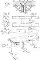
- Fig. 1 ist ein Vertikalschnitt durch eine Klammervorrichtung gemäß der Erfindung in Anwendung an zwei Platten.
- Fig. 2-7 sind ein Querschnitt und eine Längsansicht von drei in der Klammervorrichtung enthaltenen Teilen.
- Fig. 8 ist eine Perspektivansicht von zwei mittels der Klammervorrichtung gemäß der Erfindung miteinander verbundenen Tischen.
- Fig. 9 ist ein Vertikalschnitt durch eine modifizierte Klammervorrichtung gemäß der Erfindung in Anwendung an zwei Platten.
- Fig. 10 ist eine Draufsicht auf zwei Teile von mittels der Klammervorrichtung gem. Fig. 9 miteinander verbundenen Platten.
- Fig. 1 is a vertical section through a clamp device according to the invention applied to two plates.
- 2-7 are a cross-section and a longitudinal view of three parts contained in the stapler.
- Fig. 8 is a perspective view of two tables connected by means of the clamp device according to the invention.
- Fig. 9 is a vertical section through a modified clamp device according to the invention applied to two plates.
- Fig. 10 is a plan view of two parts by means of the clip device according to Fig. 9 interconnected plates.
Gemäß der in Fig. 1-8 dargestellten Ausführung zeigt Fig. 1 einen Teil von je einer Tischplatte 1,2, deren Kantenflächen 3,4 nur mit einem Teil ihrer Breite gegeneinander anliegen, im übrigen aber durch eine längs den ganzen Kantenflächen 3,4 verlaufende Kantenausfräsung 5 bzw. 6 voneinander getrennt sind. Die innere Partie der Kantenausfräsungen weist einen Schlitz 7 bzw. 8 auf. Eine annähernd U-förmige Spannschiene 9 erstreckt sich längs im wesentlichen der ganzen Länge der Kantenflächen 3,4 und ist mit auswärtsgerichteten Flanschen 10,11, Fig. 2,3, im Eingriff mit je einem Schlitz 7,8 versehen.According to the embodiment shown in FIGS. 1-8, FIG. 1 shows a part of a
Ein im wesentlichen rinnenförmiger Plattenbeschlag 12,13 ist gegen die Unterseite 1',2' der Tischplatten 1,2 und beidseitig der Spannschiene 9 parallel mit den Kantenflächen 3,4 so angebracht, daß er mit der Kantenfläche 14' einer Seite 14, Fig. 4,5, gegen die Unterseite 1',2' der betreffenden Tischplatte stößt und mit seinem anderen Seitenkantenteil 15 in eine Längsnut 16 bzw. 17 in der Unterseite 1',2' jeder Tischplatte eingreift sowie mit seiner Kantenfläche 15' vorzugsweise gegen die betreffende Tischplatte stößt. Die Außenseiten 18,19.der Plattenbeschläge 12,13 bilden miteinander einen Winkel von 90°, und die Seiten 21,22 einer rinnenförmigen Ständerschiene 20, Fig. 6,7, bilden miteinander gleichfalls einen Winkel von 90° und sind mittels mehrerer längs der Ständerschiene 20 verteilter und zwischen dieser und der Spannschiene 9 angebrachter Schrauben 23 gegen die Außenseiten 18,19 der Plattenbeschläge 12,13 angepreßt. Die Schrauben 23 sind in eine Gewindebohrung 24 in der Spannschiene 9 eingeschraubt, und ihr Kopf ruht in einem versenkten Loch 25 in der Ständerschiene.An essentially groove-shaped plate fitting 12, 13 is mounted against the underside 1 ', 2' of the
Die beschriebene erfindungsgemäße Klammervorrichtung bietet insbesondere folgende Vorteile. Bei Anziehen der Spannschrauben 23 wird die Ständerschiene 20 gegen die Plattenbeschläge 12,13 gepreßt. Aufgrund des genannten Winkels von 900 treiben die Plattenbeschläge 12,13 die Platten 1,2 dicht gegeneinander und stützen sich mittels ihrer Kantenflächen 14', 15' gegen die Unterseite der Platten 1,2 ab. Die Platten erhalten dadurch dieselbe Niveaulage, und durch die parallel mit und quer zur Ebene der Platten 1,2 wirkenden Spannkräfte werden die Platten besonders stabil miteinander verbunden. Die in einem Plattenpaar an den Kantenflächen erforderlichen Kantenausfräsungen 5,6, Schlitze 7,8 und Nuten 16,17, wie auch die in der Klammervorrichtung erforderliche Spannschiene 9, die Plattenbeschläge 12,13 und die Ständerschiene 20 einschl. der Spannschrauben sind alle leicht maschinell herzustellen, und die Platten lassen sich durch Montieren oder Abmontieren der vorliegenden Klammervorrichtung mühelos Kante an Kante miteinander verbinden oder voneinander trennen.The described clamping device according to the invention offers the following advantages in particular. When the
Die in Fig. 9 und 10 gezeigte Ausführung unterscheidet sich von der in Fig. 1-8 gezeigten im wesentlichen lediglich dadurch, daß die Ständerschiene 26 ein zwischen seinen Flanschen einen Winkel von 90° bildendes Winkeleisen ist (das wie die übrigen Teile in der Klammervorrichtung, falls dies bevorzugt wird, aus Leichtmetall besteht) und sich längs der ganzen Verbindung erstreckt. Die Plattenbeschläge 27,28 haben zwar einen ähnlichen Querschnitt wie in Fig. 1, sind aber, wie Fig. 10 zeigt, in Längsrichtung kurz und mittels Schrauben 29 befestigt. Jede Platte 31,32 hat anstelle der Längsschlitze 7,8 und Spannschiene 9 in Fig. 1 kürzere Schlitze 33,34 für einen plattenförmigen Kopf 35 der Spannschraube 36.The embodiment shown in FIGS. 9 and 10 differs from that shown in FIGS. 1-8 essentially only in that the
Auch diese erfindungsgemäße Ausführung bietet Vorteile ähnlich denen der für die Vorrichtung gem. Fig. 1-8 beschriebenen. Außerdem ist die Ausführung mit Schraubenkopf einfacher als eine Spannschiene 9. Die Montage mehrerer-Plattenbeschläge 28 bedeutet jedoch mehr Arbeit.This embodiment according to the invention also offers advantages similar to those for the device according to FIG. 1-8. In addition, the design with a screw head is simpler than a tensioning
Fig. 8 zeigt die Klammervorrichtung in Anwendung zum Verbinden von Tischplatten 1,2, wobei jede Ständerschiene 20 nahe einem Ende von einem Bein 37 mit einem mit der ganzen Länge der Ständerschiene parallelen Fuß 38 getragen wird. Die Ständerschiene kann von jeder beliebigen Anordnung getragen werden. Mit der Klammervorrichtung können die Kanten mehrerer verschiedener Gegenstände, wie Tischplatten, Regalbretter, Schaukästen in Läden, Warenhäusern, Ausstellungsräumen und Lagerlokalen, wie auch mehrteilige Gießformen zum Gießen beim Hausbau u.dgl. lösbar zusammengefügt werden.FIG. 8 shows the clamp device in use for connecting
Die Erfindung ist nicht nur auf die beschriebenen und in den Zeichnungen dargestellten Ausführungen begrenzt anzusehen, da diese insbesondere in ihrer Teilausbildung im Rahmen der Erfindung abgewandelt werden können. Der angegebene 90° Winkel z.B. kann je nach dem zwischen den resultierenden Spannkräften gewünschten gegenseitigen Größenverhältnis geändert werden. Bei Anwendung eines plattenförmigen Schraubenkopfes anstelle einer Spannschiene können die längslaufenden Kantenausfräsungen in den gegeneiranderstoßenden Kantenflächen durch lediglich eine Ausnehmung für die mit Kopf versehene Schraube ersetzt werden.The invention is not only to be regarded as limited to the embodiments described and shown in the drawings, since these can be modified in particular in their partial training within the scope of the invention. The specified 90 ° angle e.g. can be changed depending on the mutual size ratio desired between the resulting clamping forces. If a plate-shaped screw head is used instead of a tensioning rail, the longitudinal edge millings in the abutting edge surfaces can be replaced by only one recess for the screw provided with the head.
Claims (4)
Applications Claiming Priority (2)
| Application Number | Priority Date | Filing Date | Title |
|---|---|---|---|
| SE8002737A SE417236B (en) | 1980-04-11 | 1980-04-11 | CLAMP DEVICE FOR HOPPING OF DISCS |
| SE8002737 | 1980-04-11 |
Publications (2)
| Publication Number | Publication Date |
|---|---|
| EP0038469A1 true EP0038469A1 (en) | 1981-10-28 |
| EP0038469B1 EP0038469B1 (en) | 1984-11-14 |
Family
ID=20340722
Family Applications (1)
| Application Number | Title | Priority Date | Filing Date |
|---|---|---|---|
| EP81102619A Expired EP0038469B1 (en) | 1980-04-11 | 1981-04-07 | Clamping device to assemble plates |
Country Status (9)
| Country | Link |
|---|---|
| EP (1) | EP0038469B1 (en) |
| JP (1) | JPS56157979A (en) |
| AU (1) | AU548235B2 (en) |
| DE (1) | DE3167147D1 (en) |
| DK (1) | DK148986C (en) |
| FI (1) | FI69344C (en) |
| NO (1) | NO151480C (en) |
| SE (1) | SE417236B (en) |
| SU (1) | SU1178333A3 (en) |
Cited By (4)
| Publication number | Priority date | Publication date | Assignee | Title |
|---|---|---|---|---|
| GB2210131A (en) * | 1987-09-21 | 1989-06-01 | Beleggingsmaatschappij Bouwmat | Apparatus for interconnecting encased panels |
| FR2801943A1 (en) * | 1999-12-03 | 2001-06-08 | Didier Faure | DEVICE FOR ASSEMBLING WITHOUT A VIS SCREW FOR WOOD BLADES |
| WO2005095805A1 (en) * | 2004-03-29 | 2005-10-13 | D P Bakewell Limited | Arrangements for joining members together |
| CN105437181A (en) * | 2015-12-29 | 2016-03-30 | 常熟市徐润机电有限公司 | High pressure worktable |
Families Citing this family (2)
| Publication number | Priority date | Publication date | Assignee | Title |
|---|---|---|---|---|
| AU619366B2 (en) * | 1988-12-16 | 1992-01-23 | Paul H. Hartman | Radially expandable edge connector system |
| DE102014003827B4 (en) * | 2014-03-18 | 2018-02-01 | Theodor Rußler | Burr and anchor profiles |
Citations (4)
| Publication number | Priority date | Publication date | Assignee | Title |
|---|---|---|---|---|
| US3724886A (en) * | 1971-05-14 | 1973-04-03 | Svenska Flaektfabriken Ab | Joint between fireproof and pressuretight wall and ceiling elements |
| US3786611A (en) * | 1972-01-14 | 1974-01-22 | Ordeco Inc | Fastening system for joining structural members |
| NL7313621A (en) * | 1972-10-06 | 1974-04-09 | ||
| FR2435662A1 (en) * | 1978-09-08 | 1980-04-04 | Sarrau Sylviane | Construction elements for framework or partition - assembled by sliding longitudinally together over profiled section to lock |
Family Cites Families (1)
| Publication number | Priority date | Publication date | Assignee | Title |
|---|---|---|---|---|
| JPS49137312U (en) * | 1973-03-24 | 1974-11-26 |
-
1980
- 1980-04-11 SE SE8002737A patent/SE417236B/en not_active IP Right Cessation
-
1981
- 1981-03-26 FI FI810944A patent/FI69344C/en not_active IP Right Cessation
- 1981-04-07 DE DE8181102619T patent/DE3167147D1/en not_active Expired
- 1981-04-07 EP EP81102619A patent/EP0038469B1/en not_active Expired
- 1981-04-08 JP JP5376281A patent/JPS56157979A/en active Granted
- 1981-04-10 DK DK163981A patent/DK148986C/en not_active IP Right Cessation
- 1981-04-10 SU SU813276846A patent/SU1178333A3/en active
- 1981-04-10 NO NO811248A patent/NO151480C/en unknown
- 1981-10-26 AU AU76801/81A patent/AU548235B2/en not_active Ceased
Patent Citations (4)
| Publication number | Priority date | Publication date | Assignee | Title |
|---|---|---|---|---|
| US3724886A (en) * | 1971-05-14 | 1973-04-03 | Svenska Flaektfabriken Ab | Joint between fireproof and pressuretight wall and ceiling elements |
| US3786611A (en) * | 1972-01-14 | 1974-01-22 | Ordeco Inc | Fastening system for joining structural members |
| NL7313621A (en) * | 1972-10-06 | 1974-04-09 | ||
| FR2435662A1 (en) * | 1978-09-08 | 1980-04-04 | Sarrau Sylviane | Construction elements for framework or partition - assembled by sliding longitudinally together over profiled section to lock |
Cited By (6)
| Publication number | Priority date | Publication date | Assignee | Title |
|---|---|---|---|---|
| GB2210131A (en) * | 1987-09-21 | 1989-06-01 | Beleggingsmaatschappij Bouwmat | Apparatus for interconnecting encased panels |
| FR2801943A1 (en) * | 1999-12-03 | 2001-06-08 | Didier Faure | DEVICE FOR ASSEMBLING WITHOUT A VIS SCREW FOR WOOD BLADES |
| EP1106842A1 (en) * | 1999-12-03 | 2001-06-13 | Didier Fauré | Connecting device for wooden strips without visible screw |
| US6470641B1 (en) | 1999-12-03 | 2002-10-29 | Didier Faure | Assembly device without visible screws for wooden slats |
| WO2005095805A1 (en) * | 2004-03-29 | 2005-10-13 | D P Bakewell Limited | Arrangements for joining members together |
| CN105437181A (en) * | 2015-12-29 | 2016-03-30 | 常熟市徐润机电有限公司 | High pressure worktable |
Also Published As
| Publication number | Publication date |
|---|---|
| FI69344C (en) | 1986-01-10 |
| JPH0138966B2 (en) | 1989-08-17 |
| NO811248L (en) | 1981-10-12 |
| DK148986B (en) | 1985-12-09 |
| DK163981A (en) | 1981-10-12 |
| FI69344B (en) | 1985-09-30 |
| AU548235B2 (en) | 1985-12-05 |
| FI810944L (en) | 1981-10-12 |
| SE417236B (en) | 1981-03-02 |
| NO151480C (en) | 1985-04-17 |
| DE3167147D1 (en) | 1984-12-20 |
| NO151480B (en) | 1985-01-02 |
| SU1178333A3 (en) | 1985-09-07 |
| EP0038469B1 (en) | 1984-11-14 |
| JPS56157979A (en) | 1981-12-05 |
| DK148986C (en) | 1986-06-30 |
| AU7680181A (en) | 1983-05-05 |
Similar Documents
| Publication | Publication Date | Title |
|---|---|---|
| DE2437724A1 (en) | DOWELING DRILLING JIG FOR TWO FACE-SIDED WORKPIECES TO BE DOWELED TO EACH OTHER | |
| EP0790792A1 (en) | Table | |
| DE4217501A1 (en) | Mobile table unit for medical equipment - has shelves connected to stands on each side, and has fillets with connectors running around shelf, being held in position by stops | |
| EP0038469B1 (en) | Clamping device to assemble plates | |
| DE2325148C3 (en) | Device for assembling profiles for metal structures | |
| DE664346C (en) | Non-shifting clamping hook fastening of frames made of flat parts for variable capacitors or similar devices on work plates | |
| DE817191C (en) | Frame molding | |
| DE1802293A1 (en) | Furniture, such as a desk or the like. | |
| EP1123021A2 (en) | Variable workstation furniture system with vertical columns and horizontal tie-bars | |
| DE102017130758A1 (en) | Base for furniture | |
| DE2749477A1 (en) | Shelf support tubing system - is hollow rectangle in shape, with horizontal support surface for shelf, and gap into which shelf is inserted | |
| DE3701906A1 (en) | Podium stand which is intended for the construction of stages, tribunes or the like and is provided with legs which can be released if required | |
| DE19615447A1 (en) | Wall system for exhibition and trade fair stands | |
| DE4002691A1 (en) | Clamping bracket for mounting equipment on office work surface - has two main parts that can be adjusted relative to each other | |
| DE2101297A1 (en) | Laboratory table | |
| DE3232091C1 (en) | Connection of a plate-shaped piece of furniture with a crossbar | |
| EP0582104A2 (en) | Sales aid | |
| DE2944628A1 (en) | Furniture joint connector for shelves - has bridge connected by sloping arms to disc, slotted each end for threaded inserts | |
| DE3233587C2 (en) | ||
| DE2633602C3 (en) | Fitting for the detachable fastening of panel walls, support elements for boxes, shelf supports and the like on walls | |
| DE10045931A1 (en) | Clamping system has frame parts containing edge-grooves clamping elements, counter-holders, screws or tenon blocks. | |
| DE2410211A1 (en) | COMBINATION FURNITURE | |
| DE3725224A1 (en) | Shelving stand | |
| DE202005005807U1 (en) | Universal furniture item has opposed legs of metal plates with grooves for T-shaped holder parts, clamp element that engages recesses in protruding T-shaped part of holder | |
| DE1400924A1 (en) | Arrangement for detachable and adjustable fastening of metal sheets |
Legal Events
| Date | Code | Title | Description |
|---|---|---|---|
| PUAI | Public reference made under article 153(3) epc to a published international application that has entered the european phase |
Free format text: ORIGINAL CODE: 0009012 |
|
| AK | Designated contracting states |
Designated state(s): CH DE FR GB NL |
|
| 17P | Request for examination filed |
Effective date: 19811015 |
|
| GRAA | (expected) grant |
Free format text: ORIGINAL CODE: 0009210 |
|
| AK | Designated contracting states |
Designated state(s): CH DE FR GB LI NL |
|
| REF | Corresponds to: |
Ref document number: 3167147 Country of ref document: DE Date of ref document: 19841220 |
|
| ET | Fr: translation filed | ||
| PLBE | No opposition filed within time limit |
Free format text: ORIGINAL CODE: 0009261 |
|
| STAA | Information on the status of an ep patent application or granted ep patent |
Free format text: STATUS: NO OPPOSITION FILED WITHIN TIME LIMIT |
|
| 26N | No opposition filed | ||
| PGFP | Annual fee paid to national office [announced via postgrant information from national office to epo] |
Ref country code: FR Payment date: 19930225 Year of fee payment: 13 |
|
| PGFP | Annual fee paid to national office [announced via postgrant information from national office to epo] |
Ref country code: GB Payment date: 19930226 Year of fee payment: 13 |
|
| PGFP | Annual fee paid to national office [announced via postgrant information from national office to epo] |
Ref country code: CH Payment date: 19930309 Year of fee payment: 13 |
|
| PGFP | Annual fee paid to national office [announced via postgrant information from national office to epo] |
Ref country code: DE Payment date: 19930427 Year of fee payment: 13 |
|
| PGFP | Annual fee paid to national office [announced via postgrant information from national office to epo] |
Ref country code: NL Payment date: 19930430 Year of fee payment: 13 |
|
| PG25 | Lapsed in a contracting state [announced via postgrant information from national office to epo] |
Ref country code: GB Effective date: 19940407 |
|
| PG25 | Lapsed in a contracting state [announced via postgrant information from national office to epo] |
Ref country code: LI Effective date: 19940430 Ref country code: CH Effective date: 19940430 |
|
| PG25 | Lapsed in a contracting state [announced via postgrant information from national office to epo] |
Ref country code: NL Effective date: 19941101 |
|
| GBPC | Gb: european patent ceased through non-payment of renewal fee |
Effective date: 19940407 |
|
| NLV4 | Nl: lapsed or anulled due to non-payment of the annual fee | ||
| PG25 | Lapsed in a contracting state [announced via postgrant information from national office to epo] |
Ref country code: FR Effective date: 19941229 |
|
| REG | Reference to a national code |
Ref country code: CH Ref legal event code: PL |
|
| PG25 | Lapsed in a contracting state [announced via postgrant information from national office to epo] |
Ref country code: DE Effective date: 19950103 |
|
| REG | Reference to a national code |
Ref country code: FR Ref legal event code: ST |