EP0037416B1 - Microbial monitor - Google Patents
Microbial monitor Download PDFInfo
- Publication number
- EP0037416B1 EP0037416B1 EP80902099A EP80902099A EP0037416B1 EP 0037416 B1 EP0037416 B1 EP 0037416B1 EP 80902099 A EP80902099 A EP 80902099A EP 80902099 A EP80902099 A EP 80902099A EP 0037416 B1 EP0037416 B1 EP 0037416B1
- Authority
- EP
- European Patent Office
- Prior art keywords
- growth medium
- fluid
- recited
- samples
- growth
- Prior art date
- Legal status (The legal status is an assumption and is not a legal conclusion. Google has not performed a legal analysis and makes no representation as to the accuracy of the status listed.)
- Expired
Links
- 230000000813 microbial effect Effects 0.000 title claims description 9
- 239000001963 growth medium Substances 0.000 claims abstract description 77
- 239000012530 fluid Substances 0.000 claims abstract description 59
- 238000011109 contamination Methods 0.000 claims abstract description 28
- 239000007788 liquid Substances 0.000 claims abstract description 8
- 238000012544 monitoring process Methods 0.000 claims abstract description 5
- 239000007789 gas Substances 0.000 claims description 37
- 230000002285 radioactive effect Effects 0.000 claims description 20
- 210000002700 urine Anatomy 0.000 claims description 18
- 239000002609 medium Substances 0.000 claims description 14
- 238000005070 sampling Methods 0.000 claims description 12
- 238000000034 method Methods 0.000 claims description 8
- 239000000463 material Substances 0.000 claims description 7
- 230000000737 periodic effect Effects 0.000 claims description 7
- 239000007787 solid Substances 0.000 claims description 5
- 230000002503 metabolic effect Effects 0.000 abstract description 2
- 239000000203 mixture Substances 0.000 description 7
- 238000001514 detection method Methods 0.000 description 6
- 244000005700 microbiome Species 0.000 description 5
- 239000000700 radioactive tracer Substances 0.000 description 5
- 239000000758 substrate Substances 0.000 description 5
- 230000000694 effects Effects 0.000 description 3
- 238000001914 filtration Methods 0.000 description 3
- 208000015181 infectious disease Diseases 0.000 description 3
- 210000004379 membrane Anatomy 0.000 description 3
- 239000012528 membrane Substances 0.000 description 3
- 235000016709 nutrition Nutrition 0.000 description 3
- 239000002245 particle Substances 0.000 description 3
- CURLTUGMZLYLDI-UHFFFAOYSA-N Carbon dioxide Chemical compound O=C=O CURLTUGMZLYLDI-UHFFFAOYSA-N 0.000 description 2
- 239000012141 concentrate Substances 0.000 description 2
- 239000000356 contaminant Substances 0.000 description 2
- 239000003651 drinking water Substances 0.000 description 2
- 235000020188 drinking water Nutrition 0.000 description 2
- 238000011534 incubation Methods 0.000 description 2
- 238000009630 liquid culture Methods 0.000 description 2
- 230000004060 metabolic process Effects 0.000 description 2
- 239000004065 semiconductor Substances 0.000 description 2
- 239000000243 solution Substances 0.000 description 2
- OKTJSMMVPCPJKN-OUBTZVSYSA-N Carbon-13 Chemical compound [13C] OKTJSMMVPCPJKN-OUBTZVSYSA-N 0.000 description 1
- OKTJSMMVPCPJKN-NJFSPNSNSA-N Carbon-14 Chemical compound [14C] OKTJSMMVPCPJKN-NJFSPNSNSA-N 0.000 description 1
- 238000005481 NMR spectroscopy Methods 0.000 description 1
- 238000010521 absorption reaction Methods 0.000 description 1
- 239000012670 alkaline solution Substances 0.000 description 1
- 238000010420 art technique Methods 0.000 description 1
- 210000003567 ascitic fluid Anatomy 0.000 description 1
- 230000001580 bacterial effect Effects 0.000 description 1
- 238000009640 blood culture Methods 0.000 description 1
- 229910002092 carbon dioxide Inorganic materials 0.000 description 1
- 239000001569 carbon dioxide Substances 0.000 description 1
- 210000001175 cerebrospinal fluid Anatomy 0.000 description 1
- 238000000576 coating method Methods 0.000 description 1
- 239000004035 construction material Substances 0.000 description 1
- 239000013078 crystal Substances 0.000 description 1
- 238000012258 culturing Methods 0.000 description 1
- 238000010586 diagram Methods 0.000 description 1
- 238000000502 dialysis Methods 0.000 description 1
- 238000004090 dissolution Methods 0.000 description 1
- 229940079593 drug Drugs 0.000 description 1
- 239000003814 drug Substances 0.000 description 1
- 230000003203 everyday effect Effects 0.000 description 1
- 238000011010 flushing procedure Methods 0.000 description 1
- 239000012737 fresh medium Substances 0.000 description 1
- 238000007654 immersion Methods 0.000 description 1
- 238000001990 intravenous administration Methods 0.000 description 1
- 238000005304 joining Methods 0.000 description 1
- 230000014759 maintenance of location Effects 0.000 description 1
- 238000004519 manufacturing process Methods 0.000 description 1
- 238000002156 mixing Methods 0.000 description 1
- 238000012986 modification Methods 0.000 description 1
- 230000004048 modification Effects 0.000 description 1
- 230000002572 peristaltic effect Effects 0.000 description 1
- 238000002360 preparation method Methods 0.000 description 1
- 230000005855 radiation Effects 0.000 description 1
- 230000035945 sensitivity Effects 0.000 description 1
- 230000011664 signaling Effects 0.000 description 1
- FVAUCKIRQBBSSJ-UHFFFAOYSA-M sodium iodide Chemical class [Na+].[I-] FVAUCKIRQBBSSJ-UHFFFAOYSA-M 0.000 description 1
- 238000001179 sorption measurement Methods 0.000 description 1
- 238000003756 stirring Methods 0.000 description 1
- 239000000126 substance Substances 0.000 description 1
- 239000008400 supply water Substances 0.000 description 1
- 210000001635 urinary tract Anatomy 0.000 description 1
- 239000002699 waste material Substances 0.000 description 1
Images

Classifications
-
- C—CHEMISTRY; METALLURGY
- C12—BIOCHEMISTRY; BEER; SPIRITS; WINE; VINEGAR; MICROBIOLOGY; ENZYMOLOGY; MUTATION OR GENETIC ENGINEERING
- C12Q—MEASURING OR TESTING PROCESSES INVOLVING ENZYMES, NUCLEIC ACIDS OR MICROORGANISMS; COMPOSITIONS OR TEST PAPERS THEREFOR; PROCESSES OF PREPARING SUCH COMPOSITIONS; CONDITION-RESPONSIVE CONTROL IN MICROBIOLOGICAL OR ENZYMOLOGICAL PROCESSES
- C12Q1/00—Measuring or testing processes involving enzymes, nucleic acids or microorganisms; Compositions therefor; Processes of preparing such compositions
- C12Q1/02—Measuring or testing processes involving enzymes, nucleic acids or microorganisms; Compositions therefor; Processes of preparing such compositions involving viable microorganisms
- C12Q1/04—Determining presence or kind of microorganism; Use of selective media for testing antibiotics or bacteriocides; Compositions containing a chemical indicator therefor
- C12Q1/16—Determining presence or kind of microorganism; Use of selective media for testing antibiotics or bacteriocides; Compositions containing a chemical indicator therefor using radioactive material
-
- G—PHYSICS
- G01—MEASURING; TESTING
- G01N—INVESTIGATING OR ANALYSING MATERIALS BY DETERMINING THEIR CHEMICAL OR PHYSICAL PROPERTIES
- G01N33/00—Investigating or analysing materials by specific methods not covered by groups G01N1/00 - G01N31/00
- G01N33/48—Biological material, e.g. blood, urine; Haemocytometers
- G01N33/483—Physical analysis of biological material
- G01N33/497—Physical analysis of biological material of gaseous biological material, e.g. breath
Definitions
- This invention relates to a system for monitoring fluids for a microbial contamination and, more particularly, to such a system designed to automatically sample potentially con- taminatable fluid and indicate when contamination of such fluid occurs.
- the invention is particularly useful for detecting contamination of urine in catheterized patients, who are susceptible to infection of the urinary tract resulting in contamination of the urine.
- the sample such as the urine sample
- the sample had to be sent to a laboratory to be cultured so that a substantial amount of time would normally elapse between the time that the urine sample was taken and a determination made that the urine was contaminated.
- the patient often already had a massive infection.
- the present invention overcomes this problem of the prior art technique by providing a much earlier indication of the presence of contamination the fluid from which the samples are taken. This is achieved by providing at the site of a patient a liquid culture medium and periodic urine samples are automatically fed into the same tracer-labeled liquid culture medium. When contamination of the urine occurs, a contaminated sample will be fed into the culture medium and be cultured. As a result, the growth medium will evolve gas, which will be detected by a detector to provide an early indication of the presence of such gas. thus indicating the presence of microbial contamination in the urine.
- the system differs from the prior art systems, not only in the automatic sampling of the urine from the patient, but also in the fact that each urine sample is fed into the same culture medium as the previous samples. Each urine sample can be fed into the same culture medium because the system is designed only to detect the presence of contamination and the samples of urine taken from the patient prior to infection of the patient would be sterile and would not affect the ability of the culture medium to respond to a later contaminated sample.
- the system as described is also applicable to detect the presence of contamination in other fluids by automatically taking periodic samples of the fluids including fluids from wound drainage, dialysis fluids, peritoneal cavity drainage, cerebro-spinal fluid drainage, exhaled air, fluids undergoing or intended for intravenous administration or inhalation, fluids in industrial processes including food preparations, particles of solids or liquids within fluid streams, or any normally sterile or culturable fluid.
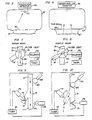
- the liquid, such as urine, being monitored from a source 11 flows through tubing 13 to an intermittent sampler 15. Fluid normally exits from the intermittent sampler 15 through tubing 17 to a suitable collector or waste disposal system, not shown. Periodically, at regular intervals, the sampler 15 directs a small sample from the fluid automatically through tubing 19 into a container 21, which contains a suitable tracer-labeled liquid growth or culture medium 23.
- the sampling rate of urine samples should be in the range of once every ten minutes to once every hour. For industrial applications, the sampling rate may be once every six hours, or very small samples may be taken at more frequent intervals.
- the container 21 has an insulating jacket and is provided with a suitable agitator 24 to stir the growth medium.
- a thermostat 26 senses the temperature within the growth medium 23 and signals a temperature control 28, which operates a heater-cooler 30 to maintain the temperature within the medium 23 to promote the growth of micro-organisms. This temperature will usually be selected to be 37°C.
- the growth medium 23 contains one or more tracer-labeled nutritional substrates, which produce tracer-containing gaseous products when metabolized.
- the composition of the medium is selected to favor the growth of categories or types of organisms of greatest importance or interest and inhibit the growth of other types of organisms.
- the composition of the medium allows evolution of the appropriate gaseous products rather than retention of the products in solution.
- the pH of the solution may be selected to release carbon dioxide.
- the culture medium is of sufficiently large volume so that the successive samples introduced into the medium through the tubing 19 have no substantial effect on the characteristics of the growth medium over a substantial period of time and for a substantial number of samples.
- the space in the container 21 over the growth medium 23 communicates through a conduit 25 with a gas detector 27.
- a gas detector 27 When the growth medium 23 evolves tracer containing gas, some of this gas will pass through the conduit 25 into the detector 27 and be detected thereby thus indicating the presence of micro-organisms in the sample introduced into the growth medium and, accordingly, indicating contamination of the fluid being monitored.
- Fig. 2 schematically illustrates an example of a radioactive gas detector which may be used in the system of Fig. 1.
- Nutritional substrates in growth medium 23 include radionuclides emitting radioactivity of sufficiently low energy that little radioactivity reaches the radioactivity detector unless a radioactive gas is produced by metabolism of the nutritional substrates.
- the detector comprises a chamber 29 having a translucent scintillation medium 31, such as an activated sodium iodide crystal radiation detector contained in a thin, gas-tight envelope, positioned at the top thereof.
- a preferred embodiment uses as scintillation medium 31 a translucent substrate using an organic scintillation medium such as "Liqui- fluor", commerically available from the New Englnd Nuclear Company.
- the substrate is moistened with an aqueous alkaline solution, 0.1 N KOH, in order to favor the dissolution of gaseous Carbon-14 dioxide, thereby bringing the radioactive gas in close proximity to the scintillation medium 31.
- a light trap 33 is provided across the mouth of the chamber 29 which communicates with the conduit 25, the light trap permitting gas to flow into the chamber 29.
- the radio emission from the radioactive gases impinges upon the scintillation medium 31, it will emit light scintillations, which, in turn, will be detected by a photomultiplier tube 35.
- the light trap 33 prevents ambient light from causing false indications by the photomultiplier tube 35, whenever light is admitted, for example, in the process of renewing the growth medium 23.
- the photomultiplier tube is protected from ambient or fluorescent light from sources other than scintillations induced by radioactive gases in the chamber 29. This protection is accomplished by the use of opaque construction materials and coatings to exclude ambient light from the system.
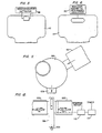
- the radioactive gas detector may comprise an ionization chamber 37, which is separated from the conduit 27 by a semipermeable membrane 41.
- the ionization chamber 37 contains electrodes 43 of an ionization detector 45.
- radioactive gas passes through the membrane 41 and into the chamber 37, it will cause ionization of the gases in the chamber 37.
- This ionization will be detected by the ionization detector 45, which will then provide an indication that the fluid being monitored has become contaminated.
- the purpose of the membrane 41 is to exclude particles from the ionization chamber 37.
- FIG. 4 A third embodiment of the radio gas detector is illustrated in Fig. 4 which employs a Geiger-Muller counter to detect the presence of radio- active gases in a chamber 47.
- the chamber 47 communicates with the conduit 27 through a thin wall 48. This wall is sufficiently thin to admit emissions from the radioactive gas in conduit 25.
- a fourth embodiment is illustrated in Fig. 5, in which a semiconductor radioactivity detector 49 is used to detect the presence of radioactive gases in chamber 47.
- FIG. 6 Another embodiment of the invention is illustrated in Fig. 6, in which a nuclear magnetic resonance analyzer 50 is used to detect change in the nuclide contents of the gas mixture in chamber 47.
- This embodiment is particularly useful for the detection of the evolution of gases containing stable nuclides as evidence of contamination in the liquid growth medium.
- the application of the invention is realized without the use of radioactive nuclides that may result in hazards associated with their use or disposal.
- gaseous Carbon-13 dioxide may be detected as a product of the metabolism by contaminating micro-organisms.
- the gas detection apparatus used in any of these embodiments is provided with an audible alarm, now shown, or other signaling device in order to alert intertested personnel to the presence of signals of contamination when detected.
- the intermittent sampler 15 may comprise a rotary valve 51 operated by a solenoid 53 controlled in turn by a timer 57.
- the rotary valve 51 comprises passageway 59 which, in the position shown in Fig. 7, directs the fluid from the tube 13 to the tube 17.
- the solenoid 53 By means of the solenoid 53, the valve 51 can be moved to the position shown in Fig. 8 in which it connects between the tube 19 and a vent 61 closed by a filter.
- the timer 57 will energize the solenoid 53, which in turn will actuate the valve 51 to the position shown in Fig. 7.
- the sample of fluid contained in the conduit 59 will be directed into the chamber 21 through the tube 19.
- the tube 19 and the tubes' 13 and 15 are implemented by flexible tubing with the tube 19 and 17 joining the tube 13 in the Y-connection 71.
- a stop clamp 73 operated by a solenoid 75 is provided to selectively close the tubing 17 just below the Y-connection 71.
- a stop clamp 77 operated by a solenoid 79 is provided to selectively close the tubing 19 just below the Y-connection 71.
- a roller 80 operated by a solenoid 83 is provided to selectively close and flush the tubing 13 above the Y-connector 17 as shown in Fig. 10.
- the solenoids 75, 77 and 83 are controlled by a timer 85.
- the solenoids will be de-energized in which case the clamp 77 will close the tube 19, the clamp 73 will leave the tube 17 open and the clamp 80 will leave the tube 13 open as illustrated in Fig. 9.
- the timer energizes the solenoids 75, 77, and 83 to cause the clamp 73 to momentarily close the tube 17, the clamp 77 to momentarily open the tube 19, and the roller 80 to momentarily close the tube 13 so that a small sample of fluid of limited volume may flow through the tube 19 into the chamber 21.
- the solenoid 83 is energized to actuate the roller 80, the roller 80 not only closes the tube 13, but also, as shown in Fig.
- roller 80 moves along a short portion of the tube 13 toward the Y-connector 17 to flush fluid in the tube 13 through the tube 19 into the chamber 21.
- the device represented by the roller 80 and the flexible tube 13 is referred to as a peristaltic pump.
- the solenoids 75, 77 and 83 are de-energized and the clamps 73 and 75 return to the position shown in Fig. 9 and the roller 80 returns to the position shown in Fig. 9.
- the sample that is intermittently directed into the chamber 21 is controlled in volume so that only a few drops may flow into the chamber 21 at the time of taking of each sample.
- it is limited to the amount contained above the clamp 77 and below the clamp 80.
- the size of the periodic sample is limited to be a small amount in this way so as not to have a significant effect upon the desirable characteristics of the growth medium.
- the volume of each sample is about 0.1 milliliters and should not exceed 1 milliliter.
- the growth medium preferably has a volume on the order of 100 times the volume of the samples and at a minimum, should be at least 10 times the volume of the samples.
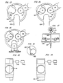
- FIGs. 11-19 illustrate two preferred embodiments of the sampler tha concentrates material from the fluid flow.
- components from the fluid stream that are suspected to be associated with contamination are collected nearly continuously in order to increase the likelihood of early detection of contamination. The collected components are then introduced into the growth medium at selected intervals.
- a sampler 99 is provided to successively and periodically transport porous collection discs into a stream being monitored and then deliver the discs to the growth medium.
- Fig. 11 schematically illustrates the apparatus viewed in elevation in the direction of fluid being monitored to the sampler 99 and
- Fig. 12 illustrates the apparatus viewed perpendicular to the direction of fluid flow.
- the sampler 99 is provided with suitable means 101 of supplying fresh discs for collecting samples to the sampler 99 and with a suitable passageway 103 to deliver discs to the chamber containing the liquid growth medium.
- the sampler 99 is connected in tubing 100 containing the flowing fluid that is to be monitored. In Fig. 11, the apparatus is illustrated without the tubing 100 connected.
- Figs. 13, 14 and 15 illustrate a cutaway view of the sampler 99 and, as shown in these figures, the sampler 99 contains a turntable 105, in the edges of which are defined three disc receiving pockets 111-113.
- Figs. 13, 14 and 15 illustrate the turntable 105 in the sampler 99 in each of three rest positions.
- a collection disc D1 from the supply means 105 calls into the pocket 111 in the turntable 105.
- the turntable 105 is rotated counterclockwise in 120° increments at predetermined intervals by means of a stepping motor 115 controlled by a timer 117 as shown in Fig. 12.
- the sequence of rotation of the turntable is from the rest position of Fig. 15.
- the disc D1 is introduced into the fluid stream flowing from the tubing 100 to the sampler 99 and a fresh disc is allowed to enter pocket 112 in the turntable 105.
- the turntable rotates after a specified collection interval to the position shown in Fig. 15. This brings fresh disc D2 into collection position, drops the disc D1 that previously occupied the collection position into the growth medium 23 for culture, and allows another fresh disc D3 to enter pocket 113 in the turntable.
- a baffle 120 may be provided in the sampler 99 in the flow path of the fluid with the baffle containing an aperture 122 aligned with and corresponding in size to the size of the discs so that the baffle directs substantially all of the fluid to flow through a disc when it is positioned in the collection in the fluid stream.
- the disc collects material from the fluid flow by filtration.
- the turntable continues to rotate in 120° increments at specified intervals, adding a collection disc to the incubation medium with each incremental rotation.
- the discs are sufficiently small in relation to the volume of the incubation medium so that the circulation of the medium remains sufficient for growth purposes after a large number of discs have been added.
- the disc may be so constructed that after immersion in the growth medium for a period of time equal to several of the specified sampling intervals, the disc disintegrates into many particles when the growth medium is agitated. This subdivision of the disc reduces any tendency of the discs to prevent free circulation of growth medium.
- a coil of fresh sample strip 131 is wound in a container 133.
- Fig. 17 schematically illustrates the apparatus in deviation viewed perpendicularly to the direction of flow of the fluid being monitored.
- Figs. 18 and 19 each illustrate an alternative arrangement of the apparatus viewed in the direction of the flow of fluid.
- the end of the sample strip is threaded through an entrance slot 135 and an exit slot 137 in the sidewall of tubing 139 so that the sample strip passes through the interior of the tubing 139 to come into contact with the fluid flowing through the tubing 139.
- the sample strip is wound on an axle 141 which is driven by a stepping motor 143 under the control of a timer 145 (see Figs. 18 and 19).
- the stepping motor 143 incrementally advances the sample strip to the tubing 139 and the sample strip collects material from the fluid flow by absorption and filtration. From the exit slit 137, the strip with the collected samples is fed to the growth medium where the sample is incubated and contamination detected as described above.
- the strip may be advanced incrementally by pinch rollers pulling the strip through the exit slot 37.
- the strip may just occupy part of the tubing allowing for part of the fluid to bypass the sample strip or the strip may be arranged to completely fill the cross-section of the tubing, as shown in Fig. 19, so that all of the fluid flows through the sample strip.
- the growth medium when sufficient uncontaminated samples have been introduced into the growth medium that they would begin to have a significant effect on the grown medium, the growth medium is replaced with a fresh growth medium.
- the chamber containing the growth medium is made disposable, and a fresh growth medium is provided simply by replacing the chamber 21 with a new chamber containing the fresh medium.
- the period at which the growth medium is replaced is selected to be short enough that the total volume of the samples introduced into the growth medium does not exceed 25 percent of the volume of the growth medium.
- the growth medium would normally be replaced once every day or two. Samples are normally added to a single growth medium for culture.
- More than one growth medium is used whenever more than a single variety of microorganism is suspected as a possible contaminant, and the growth requirements of the two or more suspected varieties of contaminant differ so that a growth medium satisfactory for one is unsatisfactory for another.
- Division of liquid samples is accomplished by means of a suitable divisiorr of the outflow of the tubing 19 (Fig. 1) into one or more replicates of chamber 21.
- a single detection device 27 serves to detect growth in all chambers 21.
- separate detectors are used in order to avoid mixing the gas mixtures in separate chambers 21.
- the replaced growth medium should continue to be incubated with a gas detector after replacement for a sufficient length of time for any contamination of the last received sample to be cultured sufficiently to give off gas to be detected by the gas detector.
Landscapes
- Health & Medical Sciences (AREA)
- Life Sciences & Earth Sciences (AREA)
- Chemical & Material Sciences (AREA)
- Engineering & Computer Science (AREA)
- Physics & Mathematics (AREA)
- Organic Chemistry (AREA)
- Molecular Biology (AREA)
- Wood Science & Technology (AREA)
- Biochemistry (AREA)
- Biomedical Technology (AREA)
- Immunology (AREA)
- General Health & Medical Sciences (AREA)
- Biophysics (AREA)
- Analytical Chemistry (AREA)
- Proteomics, Peptides & Aminoacids (AREA)
- Zoology (AREA)
- General Engineering & Computer Science (AREA)
- Urology & Nephrology (AREA)
- Toxicology (AREA)
- Microbiology (AREA)
- Genetics & Genomics (AREA)
- Biotechnology (AREA)
- Hematology (AREA)
- Bioinformatics & Cheminformatics (AREA)
- Food Science & Technology (AREA)
- Medicinal Chemistry (AREA)
- General Physics & Mathematics (AREA)
- Pathology (AREA)
- Sampling And Sample Adjustment (AREA)
- Apparatus Associated With Microorganisms And Enzymes (AREA)
- Measuring Or Testing Involving Enzymes Or Micro-Organisms (AREA)
Applications Claiming Priority (2)
| Application Number | Priority Date | Filing Date | Title |
|---|---|---|---|
| US8032779A | 1979-10-01 | 1979-10-01 | |
| US80327 | 1979-10-01 |
Publications (3)
| Publication Number | Publication Date |
|---|---|
| EP0037416A1 EP0037416A1 (en) | 1981-10-14 |
| EP0037416A4 EP0037416A4 (en) | 1982-03-29 |
| EP0037416B1 true EP0037416B1 (en) | 1984-05-16 |
Family
ID=22156689
Family Applications (1)
| Application Number | Title | Priority Date | Filing Date |
|---|---|---|---|
| EP80902099A Expired EP0037416B1 (en) | 1979-10-01 | 1981-04-08 | Microbial monitor |
Country Status (4)
| Country | Link |
|---|---|
| EP (1) | EP0037416B1 (cg-RX-API-DMAC7.html) |
| JP (1) | JPS56501271A (cg-RX-API-DMAC7.html) |
| DE (1) | DE3067866D1 (cg-RX-API-DMAC7.html) |
| WO (1) | WO1981000858A1 (cg-RX-API-DMAC7.html) |
Families Citing this family (1)
| Publication number | Priority date | Publication date | Assignee | Title |
|---|---|---|---|---|
| FR2714675B1 (fr) * | 1994-01-05 | 1996-03-08 | Inbiomed International | Procédé de mesure du 13CO2 dégagé par une culture biologique, application à l'identification des souches bactériennes, au diagnostic précoce de pousse bactérienne, à l'étude de milieux de culture. |
Family Cites Families (10)
| Publication number | Priority date | Publication date | Assignee | Title |
|---|---|---|---|---|
| US3129144A (en) * | 1962-06-29 | 1964-04-14 | Robert Z Page | Biological detection equipment |
| US4021308A (en) * | 1967-02-16 | 1977-05-03 | Rolf Saxholm | Apparatus associated with magnetically responsive, biologically active substance for testing thereof |
| US3935073A (en) * | 1970-04-22 | 1976-01-27 | Johnston Laboratories, Inc. | Method for detecting bacteria |
| US3844894A (en) * | 1971-08-30 | 1974-10-29 | Us Health Education & Welfare | Apparatus for performing assays on reactions that produce radioactive gases |
| US3956070A (en) * | 1972-04-21 | 1976-05-11 | Kenyon Charles L | Bacteria screening device for continuously monitoring and recording the existence of air borne bacteria and other microorganisms |
| US3817239A (en) * | 1972-05-12 | 1974-06-18 | D Kuntz | Urine monitor |
| US3969496A (en) * | 1973-12-28 | 1976-07-13 | Biospherics Incorporated | Use of radioisotopes for rapid identification of microorganisms |
| US3997404A (en) * | 1974-06-07 | 1976-12-14 | Johnston Laboratories, Inc. | Method and apparatus for characterizing biologically active agents |
| US3952729A (en) * | 1974-08-29 | 1976-04-27 | The Kendall Company | Diagnostic device for a liquid sample |
| FR2353856A1 (fr) * | 1976-06-02 | 1977-12-30 | Chateau Guy | Ruban destine a servir de support a une reaction par exemple chimique ou biochimique, et procede d'analyse le mettant en oeuvre |
-
1980
- 1980-09-30 JP JP50250080A patent/JPS56501271A/ja active Pending
- 1980-09-30 DE DE8080902099T patent/DE3067866D1/de not_active Expired
- 1980-09-30 WO PCT/US1980/001313 patent/WO1981000858A1/en not_active Ceased
-
1981
- 1981-04-08 EP EP80902099A patent/EP0037416B1/en not_active Expired
Non-Patent Citations (2)
| Title |
|---|
| APPLIED MICROBIOLOGY, vol. 22, no. 5, November 1971, US H.J. DE BLANC Jr. et al. "Automated radiometric detection of bacteria in 2,967 blood cultures", pages 846-849 * |
| JOURNAL OF LABORATORY AND CLINICAL MEDICINE, vol. 75, no. 3, March 1970, F. DE LAND et al. "Automated radiometric detection of bacterial growth in bloodcultures", pages 529-534 * |
Also Published As
| Publication number | Publication date |
|---|---|
| EP0037416A4 (en) | 1982-03-29 |
| JPS56501271A (cg-RX-API-DMAC7.html) | 1981-09-10 |
| WO1981000858A1 (en) | 1981-04-02 |
| DE3067866D1 (en) | 1984-06-20 |
| EP0037416A1 (en) | 1981-10-14 |
Similar Documents
| Publication | Publication Date | Title |
|---|---|---|
| US3935073A (en) | Method for detecting bacteria | |
| US5441873A (en) | Apparatus for monitoring liquids | |
| US4294931A (en) | Device for conducting microbiological radiorespirometric assays | |
| US20090215110A1 (en) | Water monitoring systems | |
| CA1256360A (en) | Apparatus and method for determining the effectiveness of sterlization | |
| PT789778E (pt) | Aparelho detector de material celular e respectivo metodo | |
| JPH0510921A (ja) | 毒物検知装置とこれを用いた水質監視システム | |
| KR20030084486A (ko) | 미생물연료전지를 이용한 수질 내 독극물 감지 장치 | |
| Högman et al. | Studies of one invasive and two noninvasive methods for detection of bacterial contamination of platelet concentrates | |
| US4590158A (en) | Microbial monitor | |
| US4248830A (en) | Device for microbiological testing | |
| Bachrach et al. | Radiometric method for the detection of coliform organisms in water | |
| EP0037416B1 (en) | Microbial monitor | |
| FI83432C (fi) | Foerfarande och anordning foer detektering av biologiskt aktiva aemnen. | |
| US5416002A (en) | Near-real-time microbial monitor | |
| US4140487A (en) | Method and apparatus for analysis of water | |
| AU6398880A (en) | Microbial monitor | |
| US3941660A (en) | Method and apparatus for detecting micro-organisms | |
| US20050221417A1 (en) | Sterility testing apparatus | |
| US6605446B2 (en) | Detecting airborne microorganisms | |
| Hawkes et al. | Design and operation of laboratory-scale anaerobic digesters: Operating experience with poultry litter | |
| EP0126019A2 (en) | High resolution method of measuring ATP, and concentrating and measuring unicellular organisms | |
| CA2075092A1 (en) | Automaton for the detection of pollution in an aqueous medium implementing a test on a type of microorganism | |
| US3819489A (en) | Bacteria detector | |
| SU795197A1 (ru) | Устройство дл контрол радиоактивности в потоке вещества |
Legal Events
| Date | Code | Title | Description |
|---|---|---|---|
| PUAI | Public reference made under article 153(3) epc to a published international application that has entered the european phase |
Free format text: ORIGINAL CODE: 0009012 |
|
| AK | Designated contracting states |
Designated state(s): DE FR GB NL SE |
|
| 17P | Request for examination filed |
Effective date: 19810922 |
|
| RBV | Designated contracting states (corrected) |
Designated state(s): DE FR GB NL SE |
|
| GRAA | (expected) grant |
Free format text: ORIGINAL CODE: 0009210 |
|
| AK | Designated contracting states |
Designated state(s): DE FR GB NL SE |
|
| PG25 | Lapsed in a contracting state [announced via postgrant information from national office to epo] |
Ref country code: SE Effective date: 19840516 Ref country code: NL Effective date: 19840516 Ref country code: FR Free format text: THE PATENT HAS BEEN ANNULLED BY A DECISION OF A NATIONAL AUTHORITY Effective date: 19840516 |
|
| REF | Corresponds to: |
Ref document number: 3067866 Country of ref document: DE Date of ref document: 19840620 |
|
| PGFP | Annual fee paid to national office [announced via postgrant information from national office to epo] |
Ref country code: DE Payment date: 19841106 Year of fee payment: 5 |
|
| NLV1 | Nl: lapsed or annulled due to failure to fulfill the requirements of art. 29p and 29m of the patents act | ||
| PLBE | No opposition filed within time limit |
Free format text: ORIGINAL CODE: 0009261 |
|
| STAA | Information on the status of an ep patent application or granted ep patent |
Free format text: STATUS: NO OPPOSITION FILED WITHIN TIME LIMIT |
|
| 26N | No opposition filed | ||
| EN | Fr: translation not filed | ||
| GBPC | Gb: european patent ceased through non-payment of renewal fee | ||
| PG25 | Lapsed in a contracting state [announced via postgrant information from national office to epo] |
Ref country code: DE Effective date: 19860603 |
|
| PG25 | Lapsed in a contracting state [announced via postgrant information from national office to epo] |
Ref country code: GB Effective date: 19881118 |