EP0036765B1 - Exhaust gas scrubber for internal combustion engines - Google Patents
Exhaust gas scrubber for internal combustion engines Download PDFInfo
- Publication number
- EP0036765B1 EP0036765B1 EP81301196A EP81301196A EP0036765B1 EP 0036765 B1 EP0036765 B1 EP 0036765B1 EP 81301196 A EP81301196 A EP 81301196A EP 81301196 A EP81301196 A EP 81301196A EP 0036765 B1 EP0036765 B1 EP 0036765B1
- Authority
- EP
- European Patent Office
- Prior art keywords
- tank
- liquid
- gases
- scrubber
- deflector
- Prior art date
- Legal status (The legal status is an assumption and is not a legal conclusion. Google has not performed a legal analysis and makes no representation as to the accuracy of the status listed.)
- Expired
Links
Images

Classifications
-
- F—MECHANICAL ENGINEERING; LIGHTING; HEATING; WEAPONS; BLASTING
- F01—MACHINES OR ENGINES IN GENERAL; ENGINE PLANTS IN GENERAL; STEAM ENGINES
- F01N—GAS-FLOW SILENCERS OR EXHAUST APPARATUS FOR MACHINES OR ENGINES IN GENERAL; GAS-FLOW SILENCERS OR EXHAUST APPARATUS FOR INTERNAL-COMBUSTION ENGINES
- F01N3/00—Exhaust or silencing apparatus having means for purifying, rendering innocuous, or otherwise treating exhaust
- F01N3/02—Exhaust or silencing apparatus having means for purifying, rendering innocuous, or otherwise treating exhaust for cooling, or for removing solid constituents of, exhaust
- F01N3/04—Exhaust or silencing apparatus having means for purifying, rendering innocuous, or otherwise treating exhaust for cooling, or for removing solid constituents of, exhaust using liquids
-
- B—PERFORMING OPERATIONS; TRANSPORTING
- B01—PHYSICAL OR CHEMICAL PROCESSES OR APPARATUS IN GENERAL
- B01D—SEPARATION
- B01D47/00—Separating dispersed particles from gases, air or vapours by liquid as separating agent
- B01D47/02—Separating dispersed particles from gases, air or vapours by liquid as separating agent by passing the gas or air or vapour over or through a liquid bath
- B01D47/025—Separating dispersed particles from gases, air or vapours by liquid as separating agent by passing the gas or air or vapour over or through a liquid bath by contacting gas and liquid with a static flow mixer
-
- Y—GENERAL TAGGING OF NEW TECHNOLOGICAL DEVELOPMENTS; GENERAL TAGGING OF CROSS-SECTIONAL TECHNOLOGIES SPANNING OVER SEVERAL SECTIONS OF THE IPC; TECHNICAL SUBJECTS COVERED BY FORMER USPC CROSS-REFERENCE ART COLLECTIONS [XRACs] AND DIGESTS
- Y02—TECHNOLOGIES OR APPLICATIONS FOR MITIGATION OR ADAPTATION AGAINST CLIMATE CHANGE
- Y02T—CLIMATE CHANGE MITIGATION TECHNOLOGIES RELATED TO TRANSPORTATION
- Y02T10/00—Road transport of goods or passengers
- Y02T10/10—Internal combustion engine [ICE] based vehicles
- Y02T10/12—Improving ICE efficiencies
-
- Y—GENERAL TAGGING OF NEW TECHNOLOGICAL DEVELOPMENTS; GENERAL TAGGING OF CROSS-SECTIONAL TECHNOLOGIES SPANNING OVER SEVERAL SECTIONS OF THE IPC; TECHNICAL SUBJECTS COVERED BY FORMER USPC CROSS-REFERENCE ART COLLECTIONS [XRACs] AND DIGESTS
- Y10—TECHNICAL SUBJECTS COVERED BY FORMER USPC
- Y10S—TECHNICAL SUBJECTS COVERED BY FORMER USPC CROSS-REFERENCE ART COLLECTIONS [XRACs] AND DIGESTS
- Y10S55/00—Gas separation
- Y10S55/30—Exhaust treatment
Definitions
- This invention relates generally to exhaust gas scrubbers for internal combustion engines, and more particularly to water scrubbers of the type which aspirate water into the stream of hot exhaust gases to cool them and remove pollutants before exhausting the gases into the atmosphere.
- Diesel engines exhaust hot sulphurous gases, aldehydes, nitrogen oxide, unburned hydrocarbons and particulate pollutants.
- Hot exhaust emissions typically 800° to 1000°F (427 to 538°C), and hot engine surfaces can ignite combustible gases and material present in underground mines, such as methane and coal dust.
- a second type of device bubbles exhaust gases through a water bath and then passes the gases through a water eliminator, as disclosed in United States Patent No. 3,768,981 (Alliger) and United States Patent No. 3,561,194 (Baldwin et al).
- Water bath devices increase back pressure on the engine more than is acceptance, particularly when full. Also, the pump used in the Baldwin device is likely to be fouled.
- a stream of exhaust gases passes through a venturi tube, causing water droplets to be sucked from a water chamber into the gas stream, as disclosed in United States Patent No. 4,137,715 (Tung-Lung et al).
- U States Patent No. 4,137,715 Tung-Lung et al.
- Filters when used in such devices, also require frequent cleaning.
- aspirated or induced water scrubbers such as that disclosed in United States Patent No. 3,976,456 (Alcock) have come into wide use.
- Such scrubbers typically include a scrubber tank partially filled with water or other scrubbing liquid.
- the exhaust gases enter the tank above the water level, are piped downwardly below the water level, and then directed upwardly at an angle.
- a submerged slot or orifice in the region where the gases change direction admits water into the gas stream.
- the gas-water mixture then enters an expansion and mixing chamber and flows upwardly above the water level. At the top of the mixing chamber the mixture is redirected downwardly by a curved duct and discharged over the water, impelling the water droplets and particles in the mixture into the water.
- the cooled exhaust gases are then discharged into the atmosphere.
- a make-up type scrubber has a make-up water tank or reservoir and a make-up float valve for adding water to the scrubber tank to maintain a desired water level.
- a batch-type scrubber has a large tank for containing enough water to run for an extended period of time before refilling. Both types are provided with a float-operated safety valve for shutting down the engine if the water level drops below a safe minimum.
- Engine back pressure is lower with aspirated water scrubbers than with other exhaust cleaning or cooling devices, but a number of other problems remain unsolved.
- aspirated water scrubbers similar in principle to the Alcock device has a specific water consumption of about 0.25 to 0.3 U.S. gallons per brake horsepower hour (1.025 x 10- 4 to 1.23 x 10- 4 litres KJ-').
- an even lower water consumption is desired to further reduce water storage requirements and steam generation.
- a further problem is the poor reliability of float- type water valves when they are exposed to the dirty, highly corrosive scrubbing liquid inside the scrubbertank. Theyfrequently malfunction or may fail to shut down the engine when the water level gets too low.
- Use of stainless steel, rather than brass floats and valves adds much to the cost of make-up type scrubbers. This problem has led mine equipment users to preferentially use batch-type aspirated water scrubbers and to use thermally-actuated engine shutdown control valves which sense the temperature of discharged exhaust gases.
- existing batch-type scrubbers pose additional problems.
- batch-type scrubber tanks have an initially higher water level than make-up scrubbers.
- the higher level causes excessive engine back pressure and discharge of water.
- Such scrubbers must also operate over a wide range of water levels, but existing scrubbers have not done so successfully.
- the Alcock design has a water level range of only about 5 inches (12.7 cm), which would require a very large tank to hold sufficient water to run 8 hours if used as a batch-type scrubber.
- Such a large tank requires more extensive baffling and stiffening to minimize sloshing and withstand the high pressures of explosions than a smaller tank would require.
- thermally-actuated control valves does not insure engine shutdown if the water level becomes too low.
- the scrubber can fail to effectively arrest flame propagation in the event of an explosion. This possibility necessitates a flame arrester in the exhaust gas orifice.
- flame arresters add to the expense of the scrubber, increase engine back pressure, particularly when they become dirty, and require daily cleaning.
- US-A-4,078,908 and U.S.-A-4,083,705 describe dump buckets for a wet-dry vacuum system comprising a container having an aperture in the bottom thereof and an aperture at the top thereof, a hollow tube extending upwardly from the lower aperture and a further hollow tube extending downwardly from the upper aperture to a tank near the bottom of the tank of the container.
- the further tube is surrounded by a mixing tube and a baffle cup surrounds the bottom end of the firsttube.
- incoming air and dirt is pulled down through the further tube and is redirected upwardly by the baffle cup below the further tube.
- the air and dirt then passes through, is filtered by, and mixes with water drawn into the annular space between the outside of the further tube and the inside of the mixing tube by the Venturi Effect and splashes against the top of the container.
- the water and dirt then separate from the air, the former returning to the water in the container and the latter passing through a filtering screen into the riser pipe. Water enters the mixing tube so as to mix with the dirt and air by means of apertures provided near the base thereof.
- US-A-4,078,908 and US-A-4,083,705 both relate to vacuum cleaning systems and do not address the particular problems associated with exhaust gas scrubbers, namely, high temperatures, corrosive liquids, engine back pressure constraints, explosive gases, high water consumption, and weight, bulk and operational constraints imposed by use in underground mining vehicle systems.
- GB-A-1,090,042 describes an apparatus for contacting a gas with a liquid for removing dust from a gas or evaporating a liquid.
- the apparatus has an outer enclosure accommodating a liquid pool, the level of which is determined by an overflow type.
- An inner casing 4 is provided in the enclosure and is connected to a gas inlet tube extending downwardly into the enclosure 1.
- the gas inlet tube is coaxial with the casing and extends within it to a level somewhat below the liquid level in the enclosure.
- a deflecting baffle having a downwardly directed skirt, the diameter of which is greater than that of the main portion of the inner casing, is attached to the gas inlet tube a short distance above the top end of the casing.
- the enclosure is provided with a gas outlet about the deflecting baffle.
- gas to be treated is introduced to the gas inlet tube so that liquid is displaced within the inner casing and fine droplets of the liquid flow with the gas upwardly away from the liquid level between the gas inner tube and the casing.
- the droplets take up dust from the gas and the mixture of gas and liquid droplets then strike the deflecting baffle the liquid droplets being separated from the gas and returned to the pool.
- the gas then passes to the gas outlet.
- an exhaust gas scrubber comprising: a scrubber tank; an exhaust gas inlet tube for conducting hot, dirty exhaust gases downwardly into the tank to an outlet opening; a mixing tube surrounding a portion of the inlet tube to define a mixing chamber between said tubes, the mixing tube extending above and below a liquid level in said tank; a deflector for reversing the flow of gases emitted from said opening to deflect said flow upwardly into the mixing chamber, the deflector including wall means extending upwardly into the mixing chamber and spaced between the mixing tube and inlet tube to define aspirator means for aspirating scrubbing liquid into the mixing chamber to intermix with, cool and cleanse said gases; means for separating the liquid from the gases; and an exhaust gas outlet for exhausting cooled, cleansed gases from said tank; the mixing tube having an open upper end and a downwardly open lower end positioned near the bottom of the scrubber tank.
- the main advantages of the present invention reside in enabling: the provision of an improved aspirated water scrubber especially suitable for use in underground mining vehicles; a reduction in the susceptibility of such scrubbers to sloshing and fluctuations in water level; the use of float- controlled valves in such scrubbers under minimum risk of malfunction; and improved scrubbing of the exhaust gases while reducing the amount of water discharged into the atmosphere.
- Embodiments of the invention may have the further advantages of avoiding the need for high cost float and valve components in aspirated water scrubbers; simplifying the structure of such scrubbers; reducing the cost of such scrubbers; minimizing engine back pressure; minimizing water consumption; providing a scrubber that will more readily withstand and dampen internal explosions; eliminating the need for flame arresters; avoiding premature engine shutdown; providing a scrubber that will operate effectively with wide variations of water level; and increasing the amount of water aspirated and uniformly mixing such water into the gases.
- the scrubber tank is vertically elongated to provide a tall, narrow pool of liquid surrounding the scrubber core to minimize sloshing and its effects.
- the relatively large scrubber tank has one pair of opposite side walls close to the scrubber core, but another pair of opposite side walls spaced far from the core.
- a pair of baffles extend between the latter walls and the core and lie close to the core to provide a relatively narrow, tall pool of water surrounding around the scrubber core, giving the same effect as the make-up type scrubber tank.
- a float may be positioned next to the scrubber core and mounted on a sealed rotating shaft which extends through a side wall of the tank.
- Water level control valves and an engine safety shut down switch may be mounted on the shaft outside the tank to isolate them from the corrosive contents of the tank.
- a make-up type water scrubber 10 comprises a scrubber tank 12, an exhaust inlet tube 14, an exhaust outlet tube 16, a scrubber core 18, a float-actuated control mechanism 20, and a make-up liquid tank and pipe (not shown).
- Scrubber tank 12 is a vertically elongate stainless steel canister having a cylindrical side wall 22 sealed at its ends by top and bottom walls 24, 26 for containing a pool of scrubbing liquid, such as water 28, and exhaust gases (not shown) above the surface of the liquid.
- the narrow, vertically elongate shape of the canister provides a deep narrow pool of liquid which is relatively immune to sloshing and normal gradient variations.
- the cylindrically-shaped tank is also unlikely to deform if an explosion occurs in the tank.
- the exhaust inlet tube 14 has a horizontal portion 30 gently curving into a vertical portion 32.
- the horizontal portion extends into the scrubber tank from an inlet flange 31 surrounding an opening in side wall 22 just below top wall 24.
- the inlet flange is adapted for connection to the exhaust pipe 55 of an internal combustion engine (not shown).
- the vertical portion leads downwardly through the centre of the tank to an exhaust opening 34 (Figure 2) spaced above bottom wall 26.
- the exhaust outlet tube 16 extends from an opening 36 in side wall 22 just below top wall 24 to emit cooled gases from the scrubber into the atmosphere or into another apparatus.
- the scrubber core 18 includes a first deflector or cup 37, an open-ended mixing tube 40 and a second deflector 42.
- Cup 37 has a cylindrical side wall 38 defining a collar concentrically surrounding the exhaust opening 34, and a bottom wall 39 spaced slightly above bottom wall 26 so that water can flow beneath the cup to cool walls 26 and 39.
- Side wall 38 extends upwardly a short distance from the inlet tube to define an annular water orifice 74 ( Figure 4) surrounding such tube.
- the cross-sectional area of orifice 74 is less than the cross-sectional area of opening 34, but not so much less than engine back pressure becomes excessive.
- a suitable ratio of such areas is in the range of 0.6 to 0.8.
- Mixing tube 40 concentrically surrounds the vertical portion of the exhaust tube and the deflector cup to define an annular expansion chamber 75 surrounding the exhaust tube and an annular water orifice 76 surrounding side wall 38, as can be seen most clearly from Figures 3 and 4.
- the lower end 41 of tube 40 is approximately level with exhaust opening 34.
- the mixing tube extends upwardly above the water level along much of the length of vertical portion 32.
- the mixing tube is spaced outwardly from the side wall of the cup a distance such that the ratio of the cross-sectional areas of orifice 74 to mixing chamber 75 is in an optimum range of 0.4 to 0.5. Greater or lesser ratios will also work, but reduce the efficiency of aspiration if too great and unduly in crease engine back pressure if too low.
- Deflector 42 forms an annular hood over the open upper end of the mixing tube just below the horizontal portion of exhaust tube 16.
- the deflector has a horizontal top wall 44 radiating outwardly from vertical portion 32 and a cylindrical side wall or skirt 46 depending from the periphery of top wall 44. The lower edge of skirt 46 overhangs the upper end of the mixing tube sufficiently to direct the mixture toward the water surface 28. Skirt 46 is spaced outwardly from the mixing tube sufficiently to further expand the mixture, but not so far as to constrict the upward flow of gases toward outlet tube 16 between the deflector and side wall 22, as indicated by arrow 80. Such flow must be less than about 600 feet per minute (3 ms-') to avoid carrying water droplets out of the scrubber.
- the scrubber is preferably designed for an average upward gas flow rate around the deflector skirt of about 400 feet per minute (2 ms-'), so that the maximum flow rate is less than about 500 feet per minute (2.5 ms- 1 ).
- Brackets or gussets interconnect the lower ends of mixing tube 40, exhaust inlet tube portion 32 and cup 37. Additional brackets (not shown) interconnect the upper ends of tube 40, tube portion 32 and deflector hood 42. Brackets also connect the mixing tube to tank side wall 22 to support the scrubber core in the tank.
- the float-actuated control mechanism 20 includes a float or stilling chamber 48 defined by a vertical baffle 49, a float 50, a rotating float shaft 52, sealed shaft fitting 54, water level sensing valves 56, 57, and safety shutdown switch or valve 58.
- baffle 49 extends along a chord between two points on the inner side of side wall 22 to define float chamber 48.
- the float chamber is preferably just large enough for float 50 to move freely up and down between the baffle and the side wall in response to changes in water level.
- the baffle has small openings 60 near bottom wall 26 to equalize the water level on opposite sides of the baffle.
- the float chamber is sufficiently tall and narrow to reduce the effects of sloshing and gradient changes on the float.
- Float 50 is connected to shaft 52 by a radial arm 51 so that changes in water level raising and lowering the float rotate the shaft within fitting 54.
- the fitting comprises a pipe fitting screwed into a mating fitting welded into an opening in side wall 22 at a position midway between high water level 66 and shut down water level 68.
- a commercial 0- ring seal (not shown) of a type which is compatible with corrosive water solutions seals the pipe fitting around shaft 52.
- Sensing valves 56, 57 are mounted on shaft 52 outside the scrubber tank, where they are isolated from corrosive scrubbing liquid.
- the valves utilize either pneumatic or hydraulic pressure to control the addition of make-up water to the scrubber tank.
- Each valve includes a cam 62 mounted for rotation on shaft 52 in position along the shaft to actuate the valve mechanism.
- Cams 62 are rotationally positioned on shaft 52 so as to actuate their respective valves at different float positions.
- the cam for sensing valve 56 is positioned to actuate valve 56 to add water to the scrubber tank from a make-up water valve and tank (not shown) when the float descends to a "refill" level 64.
- the cam of valve 57 is positioned to actuate valve 57 to cease adding make-up water when the float ascends to a "full” level 66.
- the cam in safety valve 58 is positioned to actuate valve 58 to shut down the engine (not shown) when the float descends to "shutdown" level 68 below the "refill" level.
- Sensing valves 56 and 57 keep the scrubber tank supplied with water until the make-up tank is empty, maintaining the water level above the "refill” level. Thereafter, the water level drops to the shutdown level, to activate safety shutdown valve 58, to shut down the engine before the water level gets so low that the scrubber ceases to act as an effective flame arrestor.
- Tank 12 exhaust inlet tube 14, outlet tube 16, cup 37, mixing tube 40, deflector 42, baffle 49, float 50 and fitting 54 are all preferably made of stainless steel.
- Shaft 52 is preferably bronze aluminum alloy and the 0-ring is preferably made of "Viton", a well-known brand of fluorocarbon elastomer.
- Inlet flange 31 and valves 56, 57 and 58 can be constructed of low cost corrosible components since they are unexposed to corrosive scrubber water.
- a batch-type water scrubber 110 comprises a scrubber tank 112, an exhaust inlet tube 133, an exhaust outlet tube 116, a scrubber core 118 and a float-actuated control mechanism 120.
- the batch-type scrubber uses a scrubber tank 112 whose water volume is large enough to operate for an extended length of time before refilling, for example, one eight hour work shift.
- Tank 112 is an oblong, rectangular tank with top and bottom walls 122, 124, opposite side walls 126, 128 and end walls 130, 132.
- a capped refill opening 134 is located in the top wall near end wall 132. The shape of the tank and the position of the refill opening can be changed as needed to conform to the space availability in different mining vehicles.
- Side walls 126, 128 are spaced closely together to minimize sloshing and the effects of sudden gradient changes on water level in one lateral dimension.
- Two parallel baffles 136, 138 extend across the inside of the tank between the side walls. The baffles are spaced closely together to minimize sloshing and the effect of sudden gradient changes in the other lateral dimension.
- the side walls and baffles form wall means which define tall, narrow central scrubber chamber 140 and two storage chambers 142, 144 at each end of the tank. Notches 146 at the lower corners of the baffles provide small openings for water to flow from one chamber to the other. Oblong openings 148 near the tops of each baffle allow gases to flow from one chamber to the other.
- the scrubber core is centred in the tank within chamber 140 to further minimize the effects of gradient changes.
- the exhaust inlet tube 133 has a vertical tube portion 32 extending downwardly from an inlet flange 31 surrounding an opening in upper wall 122.
- Scrubber core 118 is substantially the same as core 18 of the make-up type scrubber, except that deflector head 42 can be connected either to the underside of wall 122 or to inlet tube portion 32.
- Outlet tube 116 is connected to an opening in top wall 122 above storage chamber 142.
- Float mechanism 120 positioned along side wall 126, is substantially the same as mechanism 20 in the make-up scrubber. However, it has only one water level sensing valve or switch, safety shutdown valve 58. Float 50 is approximately centred between the baffles alongside the scrubber core. The float mechanism is positioned low enough vertically to sense the minimum level of water at which the scrubber will prevent flame propagation in case of engine backfire or an explosion in the scrubber core. Cam 62 is adjusted rotationally on shaft 52 to insure that the valve shuts down the engine when that minimum level is reached.
- both embodiments of the scrubber are initially filled with water or other suitable scrubbing liquid.
- the make-up tank is also filled.
- the batch-type scrubber is filled to a level substantially above the float but below the lower edge of deflector side wall 46. The maximum water depth should be observed in filling the scrubber tank to avoid agitation of the water surface and overly high initial water consumption and engine back pressures.
- any water inside cup 37, the mixing tube 40, and the end of exhaust tube 16 is displaced by the gases. The displaced water should not raise the water level above such maximum.
- the tank should not be filled above a maximum static water level which is about four inches (10 cm) below the skirt of the deflector hood in the make-up scrubber and about three inches (7.6 cm) below the hood in the batch scrubber, depending on tank size.
- the hot exhaust gases of an internal combustion engine travel via a water jacketed exhaust pipe 33, 133 through the scrubber exhaust inlet flange 31 into inlet tube 14, 114.
- the hot gases enter the scrubber, as indicated by arrows 70 in Figures 2 and 5, and flow downwardly toward exhaust opening 34.
- the annular orifice constricts and accelerates the flow of gases so that they flow upwardly at high velocity all around the end of exhaust tube 16 into the mixing chamber 75.
- the mixture of gases and water droplets flows upwardly around the outside of the vertical portion of the exhaust tube, which is also cooled somewhat by the water.
- a second flow reversal is effected by deflector 40 as indicated by arrows 78' in Figures 2 and 6.
- the mixture is deflected laterally and then downwardly by deflector walls 44, 46. This action impels the mixture toward the surface of water 28.
- the mixture is expanded a second time to further reduce its velocity.
- the water droplets and exhaust particles striking the water surface are thus captured.
- the now-cooled gases rise toward the top of the scrubber tank around skirt 46, as indicated by arrows 80 in Figures 2 and 6.
- the rising gases are further cooled by the downward spray of water droplets from the deflector.
- the gases then flow toward the exhaust gas outlet, as indicated by arrows 82.
- the gases exit the tank substantially free of water droplets and at a much reduced temperature and level of water-soluble and particulate pollutants.
- the overall height of the scrubber core 18, 118 is about 26 inches (66 cm).
- the diameters of the exhaust inlet tube 14, the cup 37, the mixing tube 40 and the deflector 42 are about 5 inches (13 cm), 61 inches (16.5 cm), 8 inches (20 cm) and 12 inches (30 cm), respectively.
- the cross-sectional areas of the exhaust inlet tube, the mixing chamber and the annular opening between the deflector skirt and the mixing tube are progressively greater by ratios of at least 1.5 to 1.
- the bottom wall of the cup is spaced about inch (1.25 cm) above the bottom of the tank and its side wall is about 2'1 inches (6 cm) high.
- the lower ends of the exhaust inlet tube and the mixing tube are spaced about 1; inches (4.5 cm) above the bottom wall of the tank.
- the top wall 44 of the deflector is spaced about 2" inches (6 cm) above the upper end of the mixing tube and the deflector skirt 46 extends downwardly therefrom about 5 inches (13 cm).
- a scrubber core of the foregoing dimensions was tested in a make-up scrubber tank about 34 inches (86 cm) high and having a diameter of about 18 inches (46 cm). It was found that such scrubber cooled exhaust gases to 15O-160°F (66°C-71°C) without a significant change in water consumption over a range of water depths which varied from a minimum of less than 3 inches (7.6 cm) to a maximum of about 18 inches (46 cm). When static water depth exceeded 18 inches (46 cm) or less than about 3 inches (7.6 cm) below skirt 46, water consumption increased substantially because of agitation of the water surface. Thus, the maximum static water depth during operation of the scrubber should be less than 17 inches (43 cm).
- a scrubber core of the foregoing dimensions has also been tested in a batch-type scrubber tank and has given similar results.
- the ability of the scrubber core to operate effectively over such a wide range of water depth allows a 50 per cent reduction in surface area of the tank from that required by prior batch-type scrubbers, without reducing operating time between refills. Accordingly, space requirements for batch-type scrubber tanks are substantially reduced. Sloshing and shifting of water levels within the tank due to gradient changes are likewise reduced to the point where simple baffling becomes effective. Centring the scrubber core and float in the tank reduces their susceptibility to any residual gradient changes.
- the scrubber core and exhaust inlet tube are described as being cylindrical, but the invention encompasses other geometric shapes as well.
- the vertical portion of the exhaust tube, the cup, the mixing tube, and the deflector skirt are parallel- sided cylinders.
- the mixing tube could be an inverted frustoconical tube.
- deflector hood 42 other means for separating entrained water droplets can be used. Examples include an inertical separator, or swirling tube, and water eliminating vanes.
Landscapes
- Engineering & Computer Science (AREA)
- Chemical & Material Sciences (AREA)
- Combustion & Propulsion (AREA)
- Mechanical Engineering (AREA)
- General Engineering & Computer Science (AREA)
- Chemical Kinetics & Catalysis (AREA)
- Exhaust Gas After Treatment (AREA)
- Treating Waste Gases (AREA)
- Separation Of Particles Using Liquids (AREA)
- Exhaust-Gas Circulating Devices (AREA)
Description
- This invention relates generally to exhaust gas scrubbers for internal combustion engines, and more particularly to water scrubbers of the type which aspirate water into the stream of hot exhaust gases to cool them and remove pollutants before exhausting the gases into the atmosphere.
- Reducing the pollutants and high temperatures of internal combustion engine exhaust and the temperatures of hot surfaces in underground mining vehicles is essential to the safety of mine personnel in underground coal mines. Diesel engines exhaust hot sulphurous gases, aldehydes, nitrogen oxide, unburned hydrocarbons and particulate pollutants. Hot exhaust emissions, typically 800° to 1000°F (427 to 538°C), and hot engine surfaces can ignite combustible gases and material present in underground mines, such as methane and coal dust.
- Water jacketing the engine's exhaust manifold and piping in conjunction with the engine's cooling system reduces engine surface temperatures sufficiently to meet safety requirements. However, the safety hazard and pollution problems caused by hot exhaust emissions have proven more difficult to solve. Large volumes of ventilation air must be pumped into deep mines at great cost to dilute the exhaust gases of each diesel engine used in the mine. And ventilation alone is insufficient to allay the safety hazards of hot exhaust gases in mines. Therefore, a variety of devices have been propsed for cooling and removing pollutants from the exhaust gases of internal combustion engines used in underground mines.
- One type of device, of which the exhaust cleaner proposed by White in United States Patent No. 3,383,854 is an example, sprays water or foam directly into the exhaust gas stream as it flows along a tortuous path. However, such devices increase engine back pressure, reducing effective power and time between overhauls. Water mixed with the exhaust gases becomes highly acidic and dirty with exhaust particulate matter. Consequently, the spray-type devices are also unreliable because the dirty, corrosive water fouls the pumps, nozzles and filters used in such devices, necessitating frequent cleaning. In addition, such parts must be made of stainless steel, which is very expensive.
- A second type of device bubbles exhaust gases through a water bath and then passes the gases through a water eliminator, as disclosed in United States Patent No. 3,768,981 (Alliger) and United States Patent No. 3,561,194 (Baldwin et al). Water bath devices increase back pressure on the engine more than is acceptance, particularly when full. Also, the pump used in the Baldwin device is likely to be fouled.
- In a third kind of device, a stream of exhaust gases passes through a venturi tube, causing water droplets to be sucked from a water chamber into the gas stream, as disclosed in United States Patent No. 4,137,715 (Tung-Lung et al). However, such devices tend to be very sensitive to water levels. Filters, when used in such devices, also require frequent cleaning.
- Besides the foregoing problems, many such devices inadequately mix the water and gases to effectively cleanse the gases. Also, many such devices discharge substantial amount of entrained water together with the gases, resulting in excessive water consumption and stream generation which strains the water storage capacity of the devices and impairs mine visibility.
- Because of the inadequacies of the foregoing devices, aspirated or induced water scrubbers, such as that disclosed in United States Patent No. 3,976,456 (Alcock), have come into wide use. Such scrubbers typically include a scrubber tank partially filled with water or other scrubbing liquid. The exhaust gases enter the tank above the water level, are piped downwardly below the water level, and then directed upwardly at an angle. A submerged slot or orifice in the region where the gases change direction admits water into the gas stream. The gas-water mixture then enters an expansion and mixing chamber and flows upwardly above the water level. At the top of the mixing chamber the mixture is redirected downwardly by a curved duct and discharged over the water, impelling the water droplets and particles in the mixture into the water. The cooled exhaust gases are then discharged into the atmosphere.
- Such scrubbers are of two types. A make-up type scrubber has a make-up water tank or reservoir and a make-up float valve for adding water to the scrubber tank to maintain a desired water level. A batch-type scrubber has a large tank for containing enough water to run for an extended period of time before refilling. Both types are provided with a float-operated safety valve for shutting down the engine if the water level drops below a safe minimum.
- Engine back pressure is lower with aspirated water scrubbers than with other exhaust cleaning or cooling devices, but a number of other problems remain unsolved. For example, aspirated water scrubbers similar in principle to the Alcock device, has a specific water consumption of about 0.25 to 0.3 U.S. gallons per brake horsepower hour (1.025 x 10⁻⁴ to 1.23 x 10⁻⁴ litres KJ-'). However, an even lower water consumption is desired to further reduce water storage requirements and steam generation.
- At the same time, existing scrubbers only remove about 30% of particulate exhaust emissions. About 90% of the particles emitted are less than 0.5 micrometres in diameter. Existing scrubbers either do not aspirate enough water or do not mix the water that is aspirated well enough with the gases to wet and thereby trap such small particles. In the Alcock device, water is not aspirated uniformly into the flowing gases. Moreover, the curvature of the expansion tube inhibits mixing of the water with the gases. The water is aspirated into the lower portion of the gas stream and most of it follows the outside curves of expansion tube under the influence of centrifugal force.
- Another problem is that the water in such scrubbers sloshes as the vehicle moves and the water level in the tank shifts in response to changes in gradient. The submerged orifice of such scrubbers can thus be briefly subjected to unacceptably low water levels or even exposed so that cooled, cleansed exhaust gases rather than water are drawn into the stream of hot, dirty gases, causing a momentary reduction or lapse in the scrubbing action. Changes in water level due to sloshing or gradient changes can also actuate the safety valve, causing premature shutdown of the engine. Attempts to solve this problem by use of baffles and a separate float chamber have not been successful.
- Yet another problem with existing aspirator- type scrubbers is the difficulty of producing such scrubbers and their concomitantly high manufacturing cost. In particular, the convergent inlet section and curved divergent expansion chamber are quite expensive to manufacture.
- A further problem is the poor reliability of float- type water valves when they are exposed to the dirty, highly corrosive scrubbing liquid inside the scrubbertank. Theyfrequently malfunction or may fail to shut down the engine when the water level gets too low. Use of stainless steel, rather than brass floats and valves adds much to the cost of make-up type scrubbers. This problem has led mine equipment users to preferentially use batch-type aspirated water scrubbers and to use thermally-actuated engine shutdown control valves which sense the temperature of discharged exhaust gases. However, existing batch-type scrubbers pose additional problems.
- Because they contain all the water required for up to eight hours of operation, batch-type scrubber tanks have an initially higher water level than make-up scrubbers. In existing batch scrubber designs, the higher level causes excessive engine back pressure and discharge of water. Such scrubbers must also operate over a wide range of water levels, but existing scrubbers have not done so successfully. For example, the Alcock design has a water level range of only about 5 inches (12.7 cm), which would require a very large tank to hold sufficient water to run 8 hours if used as a batch-type scrubber. Such a large tank requires more extensive baffling and stiffening to minimize sloshing and withstand the high pressures of explosions than a smaller tank would require.
- Use of thermally-actuated control valves does not insure engine shutdown if the water level becomes too low. Thus, the scrubber can fail to effectively arrest flame propagation in the event of an explosion. This possibility necessitates a flame arrester in the exhaust gas orifice. However, flame arresters add to the expense of the scrubber, increase engine back pressure, particularly when they become dirty, and require daily cleaning.
- US-A-4,078,908 and U.S.-A-4,083,705 describe dump buckets for a wet-dry vacuum system comprising a container having an aperture in the bottom thereof and an aperture at the top thereof, a hollow tube extending upwardly from the lower aperture and a further hollow tube extending downwardly from the upper aperture to a tank near the bottom of the tank of the container. The further tube is surrounded by a mixing tube and a baffle cup surrounds the bottom end of the firsttube. In use of the apparatus, incoming air and dirt is pulled down through the further tube and is redirected upwardly by the baffle cup below the further tube. The air and dirt then passes through, is filtered by, and mixes with water drawn into the annular space between the outside of the further tube and the inside of the mixing tube by the Venturi Effect and splashes against the top of the container. The water and dirt then separate from the air, the former returning to the water in the container and the latter passing through a filtering screen into the riser pipe. Water enters the mixing tube so as to mix with the dirt and air by means of apertures provided near the base thereof. US-A-4,078,908 and US-A-4,083,705 both relate to vacuum cleaning systems and do not address the particular problems associated with exhaust gas scrubbers, namely, high temperatures, corrosive liquids, engine back pressure constraints, explosive gases, high water consumption, and weight, bulk and operational constraints imposed by use in underground mining vehicle systems.
- GB-A-1,090,042 describes an apparatus for contacting a gas with a liquid for removing dust from a gas or evaporating a liquid. In the arrangement described, the apparatus has an outer enclosure accommodating a liquid pool, the level of which is determined by an overflow type. An inner casing 4 is provided in the enclosure and is connected to a gas inlet tube extending downwardly into the enclosure 1. The gas inlet tube is coaxial with the casing and extends within it to a level somewhat below the liquid level in the enclosure. A deflecting baffle having a downwardly directed skirt, the diameter of which is greater than that of the main portion of the inner casing, is attached to the gas inlet tube a short distance above the top end of the casing. The enclosure is provided with a gas outlet about the deflecting baffle. In use, gas to be treated is introduced to the gas inlet tube so that liquid is displaced within the inner casing and fine droplets of the liquid flow with the gas upwardly away from the liquid level between the gas inner tube and the casing. The droplets take up dust from the gas and the mixture of gas and liquid droplets then strike the deflecting baffle the liquid droplets being separated from the gas and returned to the pool. The gas then passes to the gas outlet. The arrangement described in GB-A-1,090,042 would not, however, be suitable for use as an exhaust gas scrubber because it lacks aspirator means which would aspirate sufficient liquid into the exhaust gas stream to cool the gas effectively and its structure would not adequately contain and dampen an explosion within the exhaust system.
- According to the present invention there is provided an exhaust gas scrubber comprising: a scrubber tank; an exhaust gas inlet tube for conducting hot, dirty exhaust gases downwardly into the tank to an outlet opening; a mixing tube surrounding a portion of the inlet tube to define a mixing chamber between said tubes, the mixing tube extending above and below a liquid level in said tank; a deflector for reversing the flow of gases emitted from said opening to deflect said flow upwardly into the mixing chamber, the deflector including wall means extending upwardly into the mixing chamber and spaced between the mixing tube and inlet tube to define aspirator means for aspirating scrubbing liquid into the mixing chamber to intermix with, cool and cleanse said gases; means for separating the liquid from the gases; and an exhaust gas outlet for exhausting cooled, cleansed gases from said tank; the mixing tube having an open upper end and a downwardly open lower end positioned near the bottom of the scrubber tank.
- The main advantages of the present invention reside in enabling: the provision of an improved aspirated water scrubber especially suitable for use in underground mining vehicles; a reduction in the susceptibility of such scrubbers to sloshing and fluctuations in water level; the use of float- controlled valves in such scrubbers under minimum risk of malfunction; and improved scrubbing of the exhaust gases while reducing the amount of water discharged into the atmosphere.
- Embodiments of the invention may have the further advantages of avoiding the need for high cost float and valve components in aspirated water scrubbers; simplifying the structure of such scrubbers; reducing the cost of such scrubbers; minimizing engine back pressure; minimizing water consumption; providing a scrubber that will more readily withstand and dampen internal explosions; eliminating the need for flame arresters; avoiding premature engine shutdown; providing a scrubber that will operate effectively with wide variations of water level; and increasing the amount of water aspirated and uniformly mixing such water into the gases.
- In a make-up type scrubber embodying the invention, the scrubber tank is vertically elongated to provide a tall, narrow pool of liquid surrounding the scrubber core to minimize sloshing and its effects.
- Similarly, in a batch-type scrubber embodying the invention, the relatively large scrubber tank has one pair of opposite side walls close to the scrubber core, but another pair of opposite side walls spaced far from the core. However, a pair of baffles extend between the latter walls and the core and lie close to the core to provide a relatively narrow, tall pool of water surrounding around the scrubber core, giving the same effect as the make-up type scrubber tank.
- A float may be positioned next to the scrubber core and mounted on a sealed rotating shaft which extends through a side wall of the tank. Water level control valves and an engine safety shut down switch may be mounted on the shaft outside the tank to isolate them from the corrosive contents of the tank.
- In order that the invention may be readily understood, embodiments thereof will now be described, by way of example, with reference to the accompanying drawings, in which:
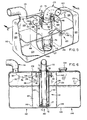
- FIGURE 1 is a perspective view of a make-up type scrubber embodying the invention, portions of the scrubber tank and core being cut away to show interior construction;
- FIGURE 2 is a vertical cross-sectional view of the scrubber of Figure 1 taken along line 2-2 in Figure 1;
- FIGURE 3 is a horizontal cross-sectional view of the scrubber of Figure 1 taken along line 3-3 in Figure 1;
- FIGURE 4 is an enlarged vertical cross-sectional view of a lower portion of Figure 3 showing aspiration of water into the mixing chamber by the exhaust gases;
- FIGURE 5 is a perspective view of a batch-type scrubber embodying the invention, portions of the tank, baffles and core being cut away to show interior construction; and
- FIGURE 6 is a vertical cross-sectional view of the scrubber of Figure 5 taken along line 6-6 in Figure 5, with only small portions of the exhaust inlet and outlet tubes being cut away.
- In the following description of two embodiments of the invention, like reference numerals identify like parts which are common to both embodiments.
- Referring to Figures 1 and 2, a make-up
type water scrubber 10 comprises ascrubber tank 12, anexhaust inlet tube 14, anexhaust outlet tube 16, ascrubber core 18, a float-actuatedcontrol mechanism 20, and a make-up liquid tank and pipe (not shown). -
Scrubber tank 12 is a vertically elongate stainless steel canister having acylindrical side wall 22 sealed at its ends by top andbottom walls water 28, and exhaust gases (not shown) above the surface of the liquid. The narrow, vertically elongate shape of the canister provides a deep narrow pool of liquid which is relatively immune to sloshing and normal gradient variations. The cylindrically-shaped tank is also unlikely to deform if an explosion occurs in the tank. - The
exhaust inlet tube 14 has ahorizontal portion 30 gently curving into avertical portion 32. The horizontal portion extends into the scrubber tank from aninlet flange 31 surrounding an opening inside wall 22 just belowtop wall 24. The inlet flange is adapted for connection to the exhaust pipe 55 of an internal combustion engine (not shown). The vertical portion leads downwardly through the centre of the tank to an exhaust opening 34 (Figure 2) spaced abovebottom wall 26. - The
exhaust outlet tube 16 extends from anopening 36 inside wall 22 just belowtop wall 24 to emit cooled gases from the scrubber into the atmosphere or into another apparatus. - The
scrubber core 18 includes a first deflector orcup 37, an open-endedmixing tube 40 and asecond deflector 42. -
Cup 37 has acylindrical side wall 38 defining a collar concentrically surrounding theexhaust opening 34, and abottom wall 39 spaced slightly abovebottom wall 26 so that water can flow beneath the cup to coolwalls Side wall 38 extends upwardly a short distance from the inlet tube to define an annular water orifice 74 (Figure 4) surrounding such tube. The cross-sectional area of orifice 74 is less than the cross-sectional area of opening 34, but not so much less than engine back pressure becomes excessive. A suitable ratio of such areas is in the range of 0.6 to 0.8. - Mixing
tube 40 concentrically surrounds the vertical portion of the exhaust tube and the deflector cup to define anannular expansion chamber 75 surrounding the exhaust tube and anannular water orifice 76 surroundingside wall 38, as can be seen most clearly from Figures 3 and 4. Thelower end 41 oftube 40 is approximately level withexhaust opening 34. The mixing tube extends upwardly above the water level along much of the length ofvertical portion 32. - The mixing tube is spaced outwardly from the side wall of the cup a distance such that the ratio of the cross-sectional areas of orifice 74 to mixing
chamber 75 is in an optimum range of 0.4 to 0.5. Greater or lesser ratios will also work, but reduce the efficiency of aspiration if too great and unduly in crease engine back pressure if too low. -
Deflector 42 forms an annular hood over the open upper end of the mixing tube just below the horizontal portion ofexhaust tube 16. The deflector has a horizontaltop wall 44 radiating outwardly fromvertical portion 32 and a cylindrical side wall orskirt 46 depending from the periphery oftop wall 44. The lower edge ofskirt 46 overhangs the upper end of the mixing tube sufficiently to direct the mixture toward thewater surface 28.Skirt 46 is spaced outwardly from the mixing tube sufficiently to further expand the mixture, but not so far as to constrict the upward flow of gases towardoutlet tube 16 between the deflector andside wall 22, as indicated byarrow 80. Such flow must be less than about 600 feet per minute (3 ms-') to avoid carrying water droplets out of the scrubber. The scrubber is preferably designed for an average upward gas flow rate around the deflector skirt of about 400 feet per minute (2 ms-'), so that the maximum flow rate is less than about 500 feet per minute (2.5 ms-1). - Brackets or gussets (not shown) interconnect the lower ends of mixing
tube 40, exhaustinlet tube portion 32 andcup 37. Additional brackets (not shown) interconnect the upper ends oftube 40,tube portion 32 anddeflector hood 42. Brackets also connect the mixing tube totank side wall 22 to support the scrubber core in the tank. - The float-actuated
control mechanism 20 includes a float or stillingchamber 48 defined by avertical baffle 49, afloat 50, arotating float shaft 52, sealed shaft fitting 54, waterlevel sensing valves valve 58. - Referring to Figure 3, baffle 49 extends along a chord between two points on the inner side of
side wall 22 to definefloat chamber 48. The float chamber is preferably just large enough forfloat 50 to move freely up and down between the baffle and the side wall in response to changes in water level. The baffle hassmall openings 60 nearbottom wall 26 to equalize the water level on opposite sides of the baffle. The float chamber is sufficiently tall and narrow to reduce the effects of sloshing and gradient changes on the float. -
Float 50 is connected toshaft 52 by aradial arm 51 so that changes in water level raising and lowering the float rotate the shaft within fitting 54. The fitting comprises a pipe fitting screwed into a mating fitting welded into an opening inside wall 22 at a position midway betweenhigh water level 66 and shut downwater level 68. A commercial 0- ring seal (not shown) of a type which is compatible with corrosive water solutions seals the pipe fitting aroundshaft 52. - Sensing
valves shaft 52 outside the scrubber tank, where they are isolated from corrosive scrubbing liquid. The valves utilize either pneumatic or hydraulic pressure to control the addition of make-up water to the scrubber tank. Each valve includes acam 62 mounted for rotation onshaft 52 in position along the shaft to actuate the valve mechanism. -
Cams 62 are rotationally positioned onshaft 52 so as to actuate their respective valves at different float positions. The cam for sensingvalve 56 is positioned to actuatevalve 56 to add water to the scrubber tank from a make-up water valve and tank (not shown) when the float descends to a "refill"level 64. The cam ofvalve 57 is positioned to actuatevalve 57 to cease adding make-up water when the float ascends to a "full"level 66. The cam insafety valve 58 is positioned to actuatevalve 58 to shut down the engine (not shown) when the float descends to "shutdown"level 68 below the "refill" level. - Sensing
valves safety shutdown valve 58, to shut down the engine before the water level gets so low that the scrubber ceases to act as an effective flame arrestor. -
Tank 12,exhaust inlet tube 14,outlet tube 16,cup 37, mixingtube 40,deflector 42,baffle 49,float 50 and fitting 54 are all preferably made of stainless steel.Shaft 52 is preferably bronze aluminum alloy and the 0-ring is preferably made of "Viton", a well-known brand of fluorocarbon elastomer.Inlet flange 31 andvalves - Referring now to Figures 5 and 6, a batch-
type water scrubber 110 comprises ascrubber tank 112, anexhaust inlet tube 133, anexhaust outlet tube 116, ascrubber core 118 and a float-actuatedcontrol mechanism 120. - Instead of employing a make-up water tank as a source of additional scrubbing water, the batch-type scrubber uses a
scrubber tank 112 whose water volume is large enough to operate for an extended length of time before refilling, for example, one eight hour work shift.Tank 112 is an oblong, rectangular tank with top andbottom walls opposite side walls walls refill opening 134 is located in the top wall nearend wall 132. The shape of the tank and the position of the refill opening can be changed as needed to conform to the space availability in different mining vehicles. -
Side walls parallel baffles - The side walls and baffles form wall means which define tall, narrow
central scrubber chamber 140 and twostorage chambers Notches 146 at the lower corners of the baffles provide small openings for water to flow from one chamber to the other.Oblong openings 148 near the tops of each baffle allow gases to flow from one chamber to the other. - The scrubber core is centred in the tank within
chamber 140 to further minimize the effects of gradient changes. Theexhaust inlet tube 133 has avertical tube portion 32 extending downwardly from aninlet flange 31 surrounding an opening inupper wall 122.Scrubber core 118 is substantially the same ascore 18 of the make-up type scrubber, except thatdeflector head 42 can be connected either to the underside ofwall 122 or toinlet tube portion 32.Outlet tube 116 is connected to an opening intop wall 122 abovestorage chamber 142. -
Float mechanism 120, positioned alongside wall 126, is substantially the same asmechanism 20 in the make-up scrubber. However, it has only one water level sensing valve or switch,safety shutdown valve 58.Float 50 is approximately centred between the baffles alongside the scrubber core. The float mechanism is positioned low enough vertically to sense the minimum level of water at which the scrubber will prevent flame propagation in case of engine backfire or an explosion in the scrubber core.Cam 62 is adjusted rotationally onshaft 52 to insure that the valve shuts down the engine when that minimum level is reached. - Preparatory to operation, both embodiments of the scrubber are initially filled with water or other suitable scrubbing liquid. In the make-up type scrubber, the make-up tank is also filled. The batch-type scrubber is filled to a level substantially above the float but below the lower edge of
deflector side wall 46. The maximum water depth should be observed in filling the scrubber tank to avoid agitation of the water surface and overly high initial water consumption and engine back pressures. When the engine is started, any water insidecup 37, the mixingtube 40, and the end ofexhaust tube 16 is displaced by the gases. The displaced water should not raise the water level above such maximum. - Accordingly, the tank should not be filled above a maximum static water level which is about four inches (10 cm) below the skirt of the deflector hood in the make-up scrubber and about three inches (7.6 cm) below the hood in the batch scrubber, depending on tank size.
- In operation of either the make-up type or the batch-type scrubber embodying the invention, the hot exhaust gases of an internal combustion engine travel via a water jacketed
exhaust pipe exhaust inlet flange 31 intoinlet tube 14, 114. The hot gases enter the scrubber, as indicated byarrows 70 in Figures 2 and 5, and flow downwardly towardexhaust opening 34. - The downwardly flowing gases exit
exhaust opening 34 and are immediately deflected laterally and then upwardly bycup 37, effecting a flow reversal, as indicated byarrows 72 in Figures 2, 4 and 6. The annular orifice constricts and accelerates the flow of gases so that they flow upwardly at high velocity all around the end ofexhaust tube 16 into the mixingchamber 75. - As the gases flow through orifice 74 into the mixing chamber, they expand to draw water through
annular water orifice 76 and aspirate such water as fine droplets uniformly into the upwardly flowing stream of gases, as indicated byarrows 78 in Figure 4. - The reversal of the flow of gases, their velocity as they pass through orifice 74, and their sudden expansion as they enter the mixing chamber combine to make the gas flow in the mixing tube quite turbulent. Such turbulence mixes the water droplets thoroughly with the gases to quickly cool the gases and to wet and thereby trap many of the particles and other pollutants in the gases.
- The mixture of gases and water droplets flows upwardly around the outside of the vertical portion of the exhaust tube, which is also cooled somewhat by the water. At the upper opening of the mixing tube, a second flow reversal is effected by
deflector 40 as indicated by arrows 78' in Figures 2 and 6. The mixture is deflected laterally and then downwardly bydeflector walls water 28. At the same time the mixture is expanded a second time to further reduce its velocity. The water droplets and exhaust particles striking the water surface are thus captured. - The now-cooled gases rise toward the top of the scrubber tank around
skirt 46, as indicated byarrows 80 in Figures 2 and 6. The rising gases are further cooled by the downward spray of water droplets from the deflector. The gases then flow toward the exhaust gas outlet, as indicated byarrows 82. The gases exit the tank substantially free of water droplets and at a much reduced temperature and level of water-soluble and particulate pollutants. - Nearly all of the scrubbing liquid not vaporized to cool the gases is returned to the pool, minimizing the need to replenish the liquid. Because of the lower water capacity of the make-up scrubber tank, water must be replenished periodically to maintain the water level. This is done automatically by the make-up float mechanism sensing the water level and adding water from the make-up tank. Because the batch-type scrubber has a very large capacity in a laterally-extending pool, its water level goes down more slowly than that of the make-up scrubber. As the water level in the central scrubber chamber between
baffles storage chambers - Backfires of the engine or explosions of combustible gases sometimes occur within the exhaust pipe or scrubber inlet tube. However, the cylindrical shape of the scrubber core resists deformation better than the square shape used in prior scrubbers. Moreover, the explosion is dampened because the increase velocity of exploded gases through opening 34 induces more water through opening 76 to cool and thereby contract the volume of the gases. The scrubber core thus absorbs and dampens such explosions to save the tank from damage and to prevent flame propagation from the exhaust outlet.
- In one example of the foregoing apparatus, the overall height of the
scrubber core exhaust inlet tube 14, thecup 37, the mixingtube 40 and thedeflector 42 are about 5 inches (13 cm), 61 inches (16.5 cm), 8 inches (20 cm) and 12 inches (30 cm), respectively. Thus, the cross-sectional areas of the exhaust inlet tube, the mixing chamber and the annular opening between the deflector skirt and the mixing tube are progressively greater by ratios of at least 1.5 to 1. The bottom wall of the cup is spaced about inch (1.25 cm) above the bottom of the tank and its side wall is about 2'1 inches (6 cm) high. The lower ends of the exhaust inlet tube and the mixing tube are spaced about 1; inches (4.5 cm) above the bottom wall of the tank. Thetop wall 44 of the deflector is spaced about 2" inches (6 cm) above the upper end of the mixing tube and thedeflector skirt 46 extends downwardly therefrom about 5 inches (13 cm). - A scrubber core of the foregoing dimensions was tested in a make-up scrubber tank about 34 inches (86 cm) high and having a diameter of about 18 inches (46 cm). It was found that such scrubber cooled exhaust gases to 15O-160°F (66°C-71°C) without a significant change in water consumption over a range of water depths which varied from a minimum of less than 3 inches (7.6 cm) to a maximum of about 18 inches (46 cm). When static water depth exceeded 18 inches (46 cm) or less than about 3 inches (7.6 cm) below
skirt 46, water consumption increased substantially because of agitation of the water surface. Thus, the maximum static water depth during operation of the scrubber should be less than 17 inches (43 cm). - Somewhat greater minimum water depth, about 5 or 6 inches (13 or 15 cm), would be required by mine safety regulations to prevent flame propagation and to insure explosion suppression. Moreover, provision for a 6 inch (15 cm) minimum water depth, still permits an 11 inch (28 cm) variation in water depth, more than twice the range of the aforementioned Alcock device. Moreover, the make-up scrubber demonstrated an average specific water consumption of less than 0.2 gallons per brake horsepower hour (8.2 x 10⁻⁵ litres kJ-'), less than 2/3rds of the water consumption of the Alcock device. The velocity of gases flowing upwardly between the deflector and the tank side wall is less than 500 feet per minute (2.5 ms-'), which helps minimize water discharge through the exhaust outlet. Finally, the engine backpressure was less than 18 inches (46 cm) of water, as measured by a water manometer, throughout the operating range of water depths of the scrubber.
- A scrubber core of the foregoing dimensions has also been tested in a batch-type scrubber tank and has given similar results. The ability of the scrubber core to operate effectively over such a wide range of water depth allows a 50 per cent reduction in surface area of the tank from that required by prior batch-type scrubbers, without reducing operating time between refills. Accordingly, space requirements for batch-type scrubber tanks are substantially reduced. Sloshing and shifting of water levels within the tank due to gradient changes are likewise reduced to the point where simple baffling becomes effective. Centring the scrubber core and float in the tank reduces their susceptibility to any residual gradient changes.
- The foregoing detailed description and example illustrate specific ways that the invention can be practiced. However, the invention is not so limited. For example, the scrubber core and exhaust inlet tube are described as being cylindrical, but the invention encompasses other geometric shapes as well. In Figures 2 and 6, the vertical portion of the exhaust tube, the cup, the mixing tube, and the deflector skirt are parallel- sided cylinders. However, non-parallel structures can also be used. For example, the mixing tube could be an inverted frustoconical tube. Besides
deflector hood 42, other means for separating entrained water droplets can be used. Examples include an inertical separator, or swirling tube, and water eliminating vanes.
Claims (17)
Applications Claiming Priority (2)
| Application Number | Priority Date | Filing Date | Title |
|---|---|---|---|
| US132855 | 1980-03-24 | ||
| US06/132,855 US4300924A (en) | 1980-03-24 | 1980-03-24 | Exhaust gas scrubber for internal combustion engines |
Publications (3)
| Publication Number | Publication Date |
|---|---|
| EP0036765A2 EP0036765A2 (en) | 1981-09-30 |
| EP0036765A3 EP0036765A3 (en) | 1982-04-14 |
| EP0036765B1 true EP0036765B1 (en) | 1988-03-16 |
Family
ID=22455904
Family Applications (1)
| Application Number | Title | Priority Date | Filing Date |
|---|---|---|---|
| EP81301196A Expired EP0036765B1 (en) | 1980-03-24 | 1981-03-19 | Exhaust gas scrubber for internal combustion engines |
Country Status (9)
| Country | Link |
|---|---|
| US (1) | US4300924A (en) |
| EP (1) | EP0036765B1 (en) |
| AU (1) | AU536218B2 (en) |
| CA (1) | CA1149731A (en) |
| DE (1) | DE3176684D1 (en) |
| DK (1) | DK110681A (en) |
| FI (1) | FI70297C (en) |
| NO (1) | NO810975L (en) |
| ZA (1) | ZA811082B (en) |
Cited By (1)
| Publication number | Priority date | Publication date | Assignee | Title |
|---|---|---|---|---|
| WO2019229772A1 (en) * | 2018-05-29 | 2019-12-05 | Chaudhari Mangesh Mohan | Device, method, and system of particulate filter for internal combustion engine |
Families Citing this family (74)
| Publication number | Priority date | Publication date | Assignee | Title |
|---|---|---|---|---|
| JPS5870895A (en) | 1981-10-26 | 1983-04-27 | Hisao Makino | Method and apparatus for multistage purification |
| GB8501354D0 (en) * | 1985-01-18 | 1985-02-20 | Ici Plc | Effecting gas-liquid contact |
| US4783958A (en) * | 1986-09-29 | 1988-11-15 | Borja Antonio B | Exhaust gas processing device and method |
| US4797132A (en) * | 1987-07-07 | 1989-01-10 | Vanvlack Edward E | Gas control apparatus |
| US4816042A (en) * | 1987-09-25 | 1989-03-28 | Baker International Corporation | Scrubber-exhaust gas conditioner |
| US5342421A (en) * | 1990-03-14 | 1994-08-30 | Wayne Technology, Inc. | Pyrolytic gas treatment system |
| US5129926A (en) * | 1991-07-22 | 1992-07-14 | Harwell James E | Engine exhaust system |
| US5192344A (en) * | 1991-09-10 | 1993-03-09 | Andre E. Thorn Bacon | Wet filter vacuum cleaner |
| US5348562A (en) * | 1992-06-16 | 1994-09-20 | Wagner Mining And Construction Equipment Co. | Exhaust gas scrubber and filter assembly |
| GB2267843B (en) * | 1992-06-16 | 1996-01-17 | Wagner Mining & Constr | Exhaust gas scrubber and filter assembly |
| JP2530592Y2 (en) * | 1993-06-28 | 1997-03-26 | 日本エスシー株式会社 | Air purification system |
| DE4331685A1 (en) * | 1993-09-17 | 1995-03-23 | Linde Ag | Procedure for operating a diving and diving |
| DE4418287C2 (en) * | 1994-05-26 | 1996-04-11 | Vogelpohl Alfons Prof Dr Ing | Device for mixing two fluids |
| US6027609A (en) * | 1994-11-04 | 2000-02-22 | Kvaener Pulping Ab | Pulp-mill recovery installation for recovering chemicals and energy from cellulose spent liquor using multiple gasifiers |
| FR2748517A1 (en) * | 1996-05-07 | 1997-11-14 | Goncalves Pereira Antonio | DEVICE FOR PURIFYING EXHAUST GASES FROM INTERNAL COMBUSTION ENGINES |
| US6035834A (en) * | 1997-02-10 | 2000-03-14 | Industrial Power Generating Corporation | Nitrogen oxides reducing aftercooler for turbocharged engines |
| US5958113A (en) * | 1997-03-18 | 1999-09-28 | Thermax, Inc. | Modular hydro filtration vacuum extraction machine |
| EP0879940A1 (en) * | 1997-05-23 | 1998-11-25 | Achille Pagani | Method and device for purification of exhaust gases |
| AU9616798A (en) * | 1997-10-08 | 1999-05-03 | D. Andrew Trivett | Gas scrubber |
| US6210468B1 (en) * | 1998-04-27 | 2001-04-03 | William D. Carson | Multiple weir scrubber |
| GB2344544B (en) * | 1998-12-09 | 2003-07-09 | James Paterson Izatt | Collecting processing and disposing of car and industrial toxic emissions |
| TW404491U (en) * | 1999-11-19 | 2000-09-01 | Wang Sheng Shiung | Air Cleaner |
| CA2364100A1 (en) * | 2001-11-30 | 2003-05-30 | Diversified Metals Engineering Ltd. | Method and apparatus for scrubbing gases, using mixing vanes |
| US6783564B2 (en) * | 2002-03-22 | 2004-08-31 | Honeywell International, Inc. | Clutch dust filter apparatus, and method of using same |
| US7112231B2 (en) * | 2002-03-22 | 2006-09-26 | Honeywell International, Inc. | Clutch filter and method for assembly |
| US7192469B1 (en) * | 2004-07-02 | 2007-03-20 | Joann Rumell, legal representative | Exhaust treatment device, system and methods for internal combustion engines |
| US7988020B2 (en) * | 2005-05-02 | 2011-08-02 | Medonyx Inc. | Wearable disinfecting gel dispenser |
| JP2007111397A (en) * | 2005-10-24 | 2007-05-10 | Izumi Products Co | Wet vacuum cleaner |
| US7530552B1 (en) | 2006-06-06 | 2009-05-12 | Enviropure Industries, Inc. | Exhaust gas treatment device and method |
| US20080035187A1 (en) * | 2006-08-14 | 2008-02-14 | Cory Andrew Brown | Fuel supply component cleaning system |
| US20080034734A1 (en) * | 2006-08-14 | 2008-02-14 | Kevin James Karkkainen | Fuel supply component cleaning system |
| US8499739B2 (en) | 2006-08-31 | 2013-08-06 | Caterpillar Inc. | Injector having tangentially oriented purge line |
| US7849682B2 (en) * | 2006-08-31 | 2010-12-14 | Caterpillar Inc | Exhaust treatment device having a fuel powered burner |
| US7721702B2 (en) * | 2006-08-31 | 2010-05-25 | Caterpillar Inc. | Spark plug having separate housing-mounted electrode |
| US8136797B2 (en) | 2007-01-19 | 2012-03-20 | Heartland Technology Partners, Llc | Cooling tower |
| US8425665B2 (en) | 2007-01-19 | 2013-04-23 | Heartland Technology Partners, Llc | Fluid scrubber |
| US8382075B2 (en) * | 2007-01-19 | 2013-02-26 | Heartland Technology Partners, Llc | Air stripper |
| US20120318009A1 (en) * | 2007-01-19 | 2012-12-20 | Heartland Technology Partners Llc | Cooling tower |
| US10005678B2 (en) | 2007-03-13 | 2018-06-26 | Heartland Technology Partners Llc | Method of cleaning a compact wastewater concentrator |
| US8679291B2 (en) | 2007-03-13 | 2014-03-25 | Heartland Technology Partners Llc | Compact wastewater concentrator using waste heat |
| US8790496B2 (en) | 2007-03-13 | 2014-07-29 | Heartland Technology Partners Llc | Compact wastewater concentrator and pollutant scrubber |
| US8741100B2 (en) | 2007-03-13 | 2014-06-03 | Heartland Technology Partners Llc | Liquid concentrator |
| US8801897B2 (en) | 2007-03-13 | 2014-08-12 | Heartland Technology Partners Llc | Compact wastewater concentrator and contaminant scrubber |
| WO2010093958A2 (en) | 2009-02-12 | 2010-08-19 | Heartland Technology Partners Llc | Compact wastewater concentrator using waste heat |
| US8601800B2 (en) * | 2009-11-02 | 2013-12-10 | Akinobu Ojima | Green muffler |
| US8250857B2 (en) * | 2009-11-03 | 2012-08-28 | Caterpillar Inc. | Exhaust aftertreatment system |
| WO2012100074A2 (en) | 2011-01-21 | 2012-07-26 | Heartland Technology Partners Llc | Condensation plume mitigation system for exhaust stacks |
| US9296624B2 (en) | 2011-10-11 | 2016-03-29 | Heartland Technology Partners Llc | Portable compact wastewater concentrator |
| US8808497B2 (en) | 2012-03-23 | 2014-08-19 | Heartland Technology Partners Llc | Fluid evaporator for an open fluid reservoir |
| US8741101B2 (en) | 2012-07-13 | 2014-06-03 | Heartland Technology Partners Llc | Liquid concentrator |
| US9199861B2 (en) * | 2013-02-07 | 2015-12-01 | Heartland Technology Partners Llc | Wastewater processing systems for power plants and other industrial sources |
| US8585869B1 (en) | 2013-02-07 | 2013-11-19 | Heartland Technology Partners Llc | Multi-stage wastewater treatment system |
| KR20160006177A (en) | 2013-05-07 | 2016-01-18 | 테네코 오토모티브 오퍼레이팅 컴파니 인코포레이티드 | Recirculating exhaust treatment fluid system |
| US9334781B2 (en) | 2013-05-07 | 2016-05-10 | Tenneco Automotive Operating Company Inc. | Vertical ultrasonic decomposition pipe |
| US9289724B2 (en) | 2013-05-07 | 2016-03-22 | Tenneco Automotive Operating Company Inc. | Flow reversing exhaust gas mixer |
| US9352276B2 (en) | 2013-05-07 | 2016-05-31 | Tenneco Automotive Operating Company Inc. | Exhaust mixing device |
| US9314750B2 (en) | 2013-05-07 | 2016-04-19 | Tenneco Automotive Operating Company Inc. | Axial flow atomization module |
| US9364790B2 (en) | 2013-05-07 | 2016-06-14 | Tenneco Automotive Operating Company Inc. | Exhaust mixing assembly |
| US9291081B2 (en) | 2013-05-07 | 2016-03-22 | Tenneco Automotive Operating Company Inc. | Axial flow atomization module |
| CN104314653A (en) * | 2014-08-25 | 2015-01-28 | 李花明 | Car muffler with function of reducing smoke dust and carbon monoxide emission |
| US9534525B2 (en) | 2015-05-27 | 2017-01-03 | Tenneco Automotive Operating Company Inc. | Mixer assembly for exhaust aftertreatment system |
| AU2017212052A1 (en) * | 2016-01-27 | 2018-08-16 | Arif Mirza Mohammad | Multipurpose air pollution and heat reducing device |
| US10478767B2 (en) * | 2016-01-27 | 2019-11-19 | Yi Fang | Air purification methodology and apparatus |
| CN105597461B (en) * | 2016-03-14 | 2017-06-06 | 中国矿业大学 | A wet dust collector |
| DE102017100318A1 (en) * | 2016-08-10 | 2018-02-15 | Sigfried Arnold | emission control system |
| CN109794120A (en) * | 2019-03-25 | 2019-05-24 | 广东洁冠能源科技有限公司 | Bubble deduster and its application method |
| US20200376406A1 (en) | 2019-05-31 | 2020-12-03 | Heartland Technology Partners Llc. | Harmful substance removal system and method |
| US20230019953A1 (en) * | 2019-12-20 | 2023-01-19 | Darbo Auto Wash Llc | System for capturing and recycling washing components |
| WO2022150441A1 (en) * | 2021-01-06 | 2022-07-14 | University Of Florida Research Foundation, Incorporated | Liquid bath air filter |
| US20230059932A1 (en) * | 2021-08-19 | 2023-02-23 | Kohler Co. | Ozone gas mitigation devices for plumbing fixtures |
| CN113521919B (en) * | 2021-09-15 | 2021-12-07 | 江苏天宇石化冶金设备有限公司 | Dust collector for waste gas of metallurgy |
| US12599860B2 (en) * | 2021-11-16 | 2026-04-14 | Edwards Vacuum Llc | Liquid filter apparatus with thermal shield |
| AT525952A1 (en) * | 2022-02-24 | 2023-09-15 | Beilschmidt Alfred | Device for treating exhaust gases from a small combustion system |
| CN117599542B (en) * | 2023-11-03 | 2026-05-08 | 哈尔滨圣泰生物制药有限公司 | A dust filtration device for laser marking machines |
Citations (1)
| Publication number | Priority date | Publication date | Assignee | Title |
|---|---|---|---|---|
| GB1090042A (en) * | 1964-03-17 | 1967-11-08 | Bahco Ab | Apparatus for contacting a gas with a liquid |
Family Cites Families (23)
| Publication number | Priority date | Publication date | Assignee | Title |
|---|---|---|---|---|
| DE48921C (en) * | E. W. HOPKINS in London, Nr. 45 Farleigh Röad, Stoke-Newington | Muffler for petroleum engines | ||
| FR337037A (en) * | ||||
| US586923A (en) * | 1897-07-20 | Tenth to frank m | ||
| FR630583A (en) * | 1927-03-09 | 1927-12-05 | Device grabbing the smoke by destroying it completely; the resulting gas is captured to be reused for various uses | |
| US2164833A (en) * | 1937-09-13 | 1939-07-04 | Joseph T Norman | Air cleaning and conditioning apparatus |
| US2612745A (en) * | 1947-12-24 | 1952-10-07 | Veechio Luigi | Apparatus for eliminating toxic gases from exhaust fumes |
| US2686399A (en) * | 1952-04-14 | 1954-08-17 | Goodman Mfg Co | Exhaust gas conditioner |
| US2877098A (en) * | 1955-02-14 | 1959-03-10 | Joseph P Ruth | Apparatus for conditioning exhaust gases from internal combustion engines |
| US3608279A (en) * | 1964-07-24 | 1971-09-28 | Carrier Corp | Apparatus for separating fatty acid distillates from vegetable oils by selective condensation and temperature control |
| GB1090092A (en) * | 1965-02-05 | 1967-11-08 | G Novosib Zd Tyazhelikh Stanko | Boring machine |
| US3485015A (en) * | 1966-03-28 | 1969-12-23 | Luigi Vecchio | Exhaust gas scrubber |
| US3383854A (en) * | 1966-11-28 | 1968-05-21 | John H. White | Internal combustion engine exhaust cleaner |
| AU415712B2 (en) * | 1967-02-17 | 1968-07-27 | E. M. Baldwin & Sons Pty. Limited | Gas conditioner |
| US3768981A (en) * | 1971-02-16 | 1973-10-30 | H Alliger | Auto exhaust scrubber with catalyst |
| AT309911B (en) * | 1971-08-13 | 1973-09-10 | Maximilian Gruber | Gas cleaning device |
| AU461078B2 (en) * | 1971-11-10 | 1975-05-15 | Improvements in or relating to vacuum cleaning systems | |
| US3976456A (en) * | 1975-04-07 | 1976-08-24 | Dresser Industries, Inc. | Gas scrubber |
| SU538145A1 (en) * | 1975-06-11 | 1976-12-05 | Предприятие П/Я А-5536 | Neutralizer for exhaust gas of an internal combustion engine |
| US4137715A (en) * | 1976-07-29 | 1979-02-06 | Tung Lung Ho | Fog smoke-filtrating and muffling device utilized by vehicle |
| US4078908A (en) * | 1976-11-24 | 1978-03-14 | Parise & Sons, Inc. | Dump bucket for a wet-dry vacuum system having improved liquid flow characteristics |
| SE7713259L (en) * | 1976-11-24 | 1978-05-25 | Parise & Sons Inc | COLLECTION CONTAINER FOR REPRESSIVE WORKING CLEANING SYSTEMS |
| GB1517115A (en) * | 1977-04-29 | 1978-07-12 | Hunslet Ltd | Exhaust gas water conditioner for an internal combustion engine |
| US4190629A (en) * | 1977-11-28 | 1980-02-26 | Domino Equipment Pty. Ltd. | Emission control apparatus for diesel engines |
-
1980
- 1980-03-24 US US06/132,855 patent/US4300924A/en not_active Expired - Lifetime
-
1981
- 1981-02-19 ZA ZA00811082A patent/ZA811082B/en unknown
- 1981-02-24 AU AU67585/81A patent/AU536218B2/en not_active Ceased
- 1981-02-27 CA CA000372071A patent/CA1149731A/en not_active Expired
- 1981-03-11 DK DK110681A patent/DK110681A/en not_active Application Discontinuation
- 1981-03-19 EP EP81301196A patent/EP0036765B1/en not_active Expired
- 1981-03-19 DE DE8181301196T patent/DE3176684D1/en not_active Expired
- 1981-03-23 FI FI810895A patent/FI70297C/en not_active IP Right Cessation
- 1981-03-23 NO NO810975A patent/NO810975L/en unknown
Patent Citations (1)
| Publication number | Priority date | Publication date | Assignee | Title |
|---|---|---|---|---|
| GB1090042A (en) * | 1964-03-17 | 1967-11-08 | Bahco Ab | Apparatus for contacting a gas with a liquid |
Cited By (1)
| Publication number | Priority date | Publication date | Assignee | Title |
|---|---|---|---|---|
| WO2019229772A1 (en) * | 2018-05-29 | 2019-12-05 | Chaudhari Mangesh Mohan | Device, method, and system of particulate filter for internal combustion engine |
Also Published As
| Publication number | Publication date |
|---|---|
| NO810975L (en) | 1981-10-27 |
| DE3176684D1 (en) | 1988-04-21 |
| FI810895L (en) | 1981-09-25 |
| FI70297B (en) | 1986-02-28 |
| CA1149731A (en) | 1983-07-12 |
| EP0036765A2 (en) | 1981-09-30 |
| AU536218B2 (en) | 1984-04-19 |
| EP0036765A3 (en) | 1982-04-14 |
| AU6758581A (en) | 1981-10-01 |
| US4300924A (en) | 1981-11-17 |
| ZA811082B (en) | 1982-03-31 |
| FI70297C (en) | 1986-09-15 |
| DK110681A (en) | 1981-09-25 |
Similar Documents
| Publication | Publication Date | Title |
|---|---|---|
| US4300924A (en) | Exhaust gas scrubber for internal combustion engines | |
| JPH0554365B2 (en) | ||
| JPH0643587Y2 (en) | Degassing device for pipeline system | |
| KR101331002B1 (en) | Cleaning apparatus for exhaust gas of ship | |
| US3130024A (en) | Apparatus for separating foreign matter from air | |
| GB2197221A (en) | Degasifier | |
| US5972061A (en) | Wellhead separation system | |
| CN110384997A (en) | Lampblack purifying system based on whirlwind spray | |
| CN2305242Y (en) | Wet composite smoke purifier for boiler | |
| CN2405643Y (en) | Impulse-type efficient smoke-purifying apparatus | |
| US3651620A (en) | Gas scrubber | |
| CN111892182A (en) | Ship desulfurization washing water circulation cabin, ship desulfurization system and ship | |
| CN111151113A (en) | Waste incineration flue gas sprays deacidification tower | |
| CN201320440Y (en) | Furnace smoke dust processor | |
| CN206409281U (en) | Vent gas treatment water tank | |
| CN213542525U (en) | Dust collector and boiler of boiler | |
| CN115720529A (en) | Cyclone type exhaust gas purification device | |
| JPS5942083Y2 (en) | Gas-liquid separator | |
| CN2888249Y (en) | Multifunctional tank with functions of flash evaporation, liquid separation and water seal for combustible gas emptying | |
| CN1237310C (en) | Exhaust hood purified though dipping path | |
| EP0541293B1 (en) | A valve | |
| RU2078722C1 (en) | Reservoir for crude oil and oil products | |
| SU1153957A1 (en) | Separator for gases and liquids | |
| SU860829A1 (en) | Gas-liquid separator | |
| SU1110914A1 (en) | Device for cleaning exhaust gases of internal combustion engine |
Legal Events
| Date | Code | Title | Description |
|---|---|---|---|
| PUAI | Public reference made under article 153(3) epc to a published international application that has entered the european phase |
Free format text: ORIGINAL CODE: 0009012 |
|
| AK | Designated contracting states |
Designated state(s): DE FR GB SE |
|
| PUAL | Search report despatched |
Free format text: ORIGINAL CODE: 0009013 |
|
| AK | Designated contracting states |
Designated state(s): DE FR GB SE |
|
| DET | De: translation of patent claims | ||
| 17P | Request for examination filed |
Effective date: 19820510 |
|
| GRAA | (expected) grant |
Free format text: ORIGINAL CODE: 0009210 |
|
| AK | Designated contracting states |
Kind code of ref document: B1 Designated state(s): DE FR GB SE |
|
| REF | Corresponds to: |
Ref document number: 3176684 Country of ref document: DE Date of ref document: 19880421 |
|
| ET | Fr: translation filed | ||
| PLBE | No opposition filed within time limit |
Free format text: ORIGINAL CODE: 0009261 |
|
| STAA | Information on the status of an ep patent application or granted ep patent |
Free format text: STATUS: NO OPPOSITION FILED WITHIN TIME LIMIT |
|
| 26N | No opposition filed | ||
| REG | Reference to a national code |
Ref country code: GB Ref legal event code: 732 |
|
| REG | Reference to a national code |
Ref country code: FR Ref legal event code: TP |
|
| EAL | Se: european patent in force in sweden |
Ref document number: 81301196.2 |
|
| PGFP | Annual fee paid to national office [announced via postgrant information from national office to epo] |
Ref country code: GB Payment date: 19970310 Year of fee payment: 17 |
|
| PGFP | Annual fee paid to national office [announced via postgrant information from national office to epo] |
Ref country code: FR Payment date: 19970313 Year of fee payment: 17 |
|
| PGFP | Annual fee paid to national office [announced via postgrant information from national office to epo] |
Ref country code: SE Payment date: 19970319 Year of fee payment: 17 |
|
| PGFP | Annual fee paid to national office [announced via postgrant information from national office to epo] |
Ref country code: DE Payment date: 19970401 Year of fee payment: 17 |
|
| PG25 | Lapsed in a contracting state [announced via postgrant information from national office to epo] |
Ref country code: GB Free format text: LAPSE BECAUSE OF NON-PAYMENT OF DUE FEES Effective date: 19980319 |
|
| PG25 | Lapsed in a contracting state [announced via postgrant information from national office to epo] |
Ref country code: SE Free format text: LAPSE BECAUSE OF NON-PAYMENT OF DUE FEES Effective date: 19980320 |
|
| PG25 | Lapsed in a contracting state [announced via postgrant information from national office to epo] |
Ref country code: FR Free format text: THE PATENT HAS BEEN ANNULLED BY A DECISION OF A NATIONAL AUTHORITY Effective date: 19980331 |
|
| GBPC | Gb: european patent ceased through non-payment of renewal fee |
Effective date: 19980319 |
|
| PG25 | Lapsed in a contracting state [announced via postgrant information from national office to epo] |
Ref country code: DE Free format text: LAPSE BECAUSE OF NON-PAYMENT OF DUE FEES Effective date: 19981201 |
|
| EUG | Se: european patent has lapsed |
Ref document number: 81301196.2 |
|
| REG | Reference to a national code |
Ref country code: FR Ref legal event code: ST |
|
| APAH | Appeal reference modified |
Free format text: ORIGINAL CODE: EPIDOSCREFNO |