EP0036752B1 - Protection apparatus for electric power transmission systems - Google Patents
Protection apparatus for electric power transmission systems Download PDFInfo
- Publication number
- EP0036752B1 EP0036752B1 EP81301137A EP81301137A EP0036752B1 EP 0036752 B1 EP0036752 B1 EP 0036752B1 EP 81301137 A EP81301137 A EP 81301137A EP 81301137 A EP81301137 A EP 81301137A EP 0036752 B1 EP0036752 B1 EP 0036752B1
- Authority
- EP
- European Patent Office
- Prior art keywords
- feeder
- mutual coupling
- zero sequence
- signal
- proportional
- Prior art date
- Legal status (The legal status is an assumption and is not a legal conclusion. Google has not performed a legal analysis and makes no representation as to the accuracy of the status listed.)
- Expired
Links
- 230000005540 biological transmission Effects 0.000 title claims description 9
- 230000008878 coupling Effects 0.000 claims description 26
- 238000010168 coupling process Methods 0.000 claims description 26
- 238000005859 coupling reaction Methods 0.000 claims description 26
- 230000000670 limiting effect Effects 0.000 claims description 12
- 230000007935 neutral effect Effects 0.000 claims description 6
- 238000010586 diagram Methods 0.000 description 5
- 238000000034 method Methods 0.000 description 3
- 230000000694 effects Effects 0.000 description 2
- FWNOUYXMHAJQMU-DBRKOABJSA-N (2s,3s,4r,5r)-2-(iodomethyl)-5-(2-nitroimidazol-1-yl)oxolane-3,4-diol Chemical compound O1[C@H](CI)[C@@H](O)[C@@H](O)[C@@H]1N1C([N+]([O-])=O)=NC=C1 FWNOUYXMHAJQMU-DBRKOABJSA-N 0.000 description 1
- 230000002411 adverse Effects 0.000 description 1
- 238000013459 approach Methods 0.000 description 1
- 238000010276 construction Methods 0.000 description 1
- 230000001934 delay Effects 0.000 description 1
- 230000001939 inductive effect Effects 0.000 description 1
- 238000005259 measurement Methods 0.000 description 1
- 230000001681 protective effect Effects 0.000 description 1
- 230000001052 transient effect Effects 0.000 description 1
Images


Classifications
-
- H—ELECTRICITY
- H02—GENERATION; CONVERSION OR DISTRIBUTION OF ELECTRIC POWER
- H02H—EMERGENCY PROTECTIVE CIRCUIT ARRANGEMENTS
- H02H3/00—Emergency protective circuit arrangements for automatic disconnection directly responsive to an undesired change from normal electric working condition with or without subsequent reconnection ; integrated protection
- H02H3/40—Emergency protective circuit arrangements for automatic disconnection directly responsive to an undesired change from normal electric working condition with or without subsequent reconnection ; integrated protection responsive to ratio of voltage and current
- H02H3/402—Emergency protective circuit arrangements for automatic disconnection directly responsive to an undesired change from normal electric working condition with or without subsequent reconnection ; integrated protection responsive to ratio of voltage and current using homopolar quantities
-
- H—ELECTRICITY
- H02—GENERATION; CONVERSION OR DISTRIBUTION OF ELECTRIC POWER
- H02H—EMERGENCY PROTECTIVE CIRCUIT ARRANGEMENTS
- H02H7/00—Emergency protective circuit arrangements specially adapted for specific types of electric machines or apparatus or for sectionalised protection of cable or line systems, and effecting automatic switching in the event of an undesired change from normal working conditions
- H02H7/26—Sectionalised protection of cable or line systems, e.g. for disconnecting a section on which a short-circuit, earth fault, or arc discharge has occured
- H02H7/267—Sectionalised protection of cable or line systems, e.g. for disconnecting a section on which a short-circuit, earth fault, or arc discharge has occured for parallel lines and wires
Definitions
- This invention relates to protection apparatus for electrical power transmission systems.
- the mutual coupling compensation signal be controlled in dependence on the ratio of the zero sequence currents in the other feeder and the protected feeder, the compensation being cut- .off when the ratio exceeds a predetermined value.
- Such an arrangement has the disadvantage that quite a substantial time is necessary to arrive at a decision as to whether or not to cutoff the compensation and to effect cutting-off of the compensation.
- Such an arrangement is not suitable for use in modern protection apparatus in which minimum operating times of 5 milliseconds or even lower are common.
- the mutual coupling compensation signal is controlled in dependence on the ratio of the zero sequence currents in the other feeder and said feeder
- the mutual coupling compensation signal is arranged to be proportional to the zero sequence current in the other feeder when the ratio of the zero sequence currents in the other feeder and said feeder is below a predetermined value, and when said ratio is above said predetermined value is limited to a value proportional to the zero sequence current in said feeder.
- the required limiting can be effected almost instantaneously and does not involve the sort of time delay which is necessary with the prior art arrangement wherein before cutting-off the mutual coupling compensation it is desirable to be sure that the high zero sequence current ratio condition is a permanent condition and not merely a transient condition.
- the transmission system comprises a parallel pair of feeders G and H connecting two sources of 3-phase a.c. electrical power S1 and S2, the required 3- phase line arrangements being indicated by single lines in Figure 1.
- the feeders are protected by four circuit breakers CB1 to CB4 one connected at each end of each feeder.
- the circuit breakers are controlled by respective distance relays DR1 to DR4.
- Each relay determines the values relative to set values of various impedances of its associated feeder in a direction towards the other distance relay associated with that feeder, and on the basis of the result of such determination makes a decision as to whether its associated circuit breaker should be opened.
- the relay is supplied by way of current transformers (not shown) with currents I A , I B and I C respectively representative of the currents of the three phases of the associated feeder H.
- the currents I A , I B and I C are also summed and the resultant current I N ' which is three times the zero sequence current of the feeder H, is used to provide neutral compensation of the earth fault impedance determining elements in the relay.
- currents representative of the phase currents of the parallel feeder G are summed to provide a current I M representative of three times the zero sequence current of the feeder G, this current being used to provide mutual coupling compensation of the earth fault impedance determing elements in the relay.
- the relay includes impedance replicas Z ⁇ , Z N and Z,, represented by block 1 in Figure 2, whose magnitudes and phase angles determine the phase impedance, neutral compensation and mutual coupling compensation settings respectively of the relay. These impedance replicas together with the current inputs are utilised to produce voltages I A Z R , I B Z R , I C Z R , I N Z N and I M Z M . These voltages together with voltages V A , V B , V e and V N respectively representative of the phase and neutral voltages of the feeder H are fed to decision making elements 3 of the relay wherein a decision is made as to whether the associated circuit breaker should be opened.
- the constant K is chosen to split the gap between the correct compensation conditions and the limiting conditions thus giving a safety margin for both situations.
- the limit is always above the I M Z M signal and therefore does not influence the signal.
- the limiting action comes in before the mutual compensation is large enough to cause maloperation.
- Studies have shown that a K value of 1.5 will generally give adequate safety margins between conditions requiring correct mutual compensation and those requiring limiting.
- the K value can be made adjustable, if desired, in case 1.5 proved unsuitable for particular power systems.
- the response time of the dynamic control circuit must be faster than the operating time of the distance relay to which it is applied.
- the trend in new designs of such relays is for minimum operating times of around 0.25 cycles or 5 mS for a 50 Hz system.
- the proposed control has no inherent delays and is suitable for application for very high speed protection.
- One practical arrangement which has been built and tested has a speed of response of typically 1 mS.
- the type of limiting required depends on the measurement principles of the protection to which it is applied. There are two possible forms, peak limiting and waveshape limiting. The former is simple and inexpensive, however, difficulties can arise because the signal I M Z M ' approaches a square wave as the ratio of I M Z M to I N Z N increases. Some relays could be adversely affected by one of the input signals having a square instead of a sine waveshape. This is easily overcome by controlling the waveshape such that it has an approximate sine waveshape. This method is considered suitable for all known measuring principles used in relays. Since the limiting is applied only to prevent maloperation then the I M Z M ' signal can have significant distortion under these conditions. The critical factor tends to be the maximum rate of rise of any part of the waveform, and it is this which must be controlled.
- the circuit comprises a two-stage feedback amplifier arrangement comprising operational amplifiers 7 and 9 to which the signal I N Z N is applied as input, the arrangement providing an output of 1.5 I N Z N at the output of the second amplifier 9.
- the output of the amplifier 9 is applied to a further operational amplifier 11 which serves to limit excursions of one polarity of the signal on a pair of lines 13 and 15, to which the signal I M Z M is applied via a resistor 17, to the value 1.5 I N Z N .
- a further amplifier 19 to which the output of amplifier 9 is applied via an inverter comprising an operational amplifier 21 serves to limit excursions of the signal on the lines 13 and 15 of the other polarity to the value 1.5 INZ N .
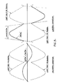
- Figure 5 gives examples of the signal waveforms for the unlimited and the limited conditions.
- the power system parameters dictate that the currents I N and I M will be close to being either in-phase or anti-phase, this helps in the case where waveshape limiting is applied, as shown in the diagrams.
- the unlimited condition waveforms are an example of a fault on the protected feeder where the mutual compensation is less than Kl N Z N and therefore the signal I M Z M ' is the correct mutual compensation.
- the limited condition waveforms are typical of faults on the parallel feeder where maloperation on standard mutual compensation could occur.
- the input signal I M Z M is much greater than Kl N Z N and hence the limits apply and control the size of the signal I M Z M '. This signal shows some distortion, but this is unlikely to cause problems in the distance relay. If necessary, the signal I M Z M can be filtered to reduce the distortion.
Landscapes
- Emergency Protection Circuit Devices (AREA)
Applications Claiming Priority (2)
| Application Number | Priority Date | Filing Date | Title |
|---|---|---|---|
| GB8009709 | 1980-03-21 | ||
| GB8009709 | 1980-03-21 |
Publications (2)
| Publication Number | Publication Date |
|---|---|
| EP0036752A1 EP0036752A1 (en) | 1981-09-30 |
| EP0036752B1 true EP0036752B1 (en) | 1984-06-27 |
Family
ID=10512296
Family Applications (1)
| Application Number | Title | Priority Date | Filing Date |
|---|---|---|---|
| EP81301137A Expired EP0036752B1 (en) | 1980-03-21 | 1981-03-18 | Protection apparatus for electric power transmission systems |
Country Status (5)
| Country | Link |
|---|---|
| US (1) | US4370691A (ref) |
| EP (1) | EP0036752B1 (ref) |
| AU (1) | AU540253B2 (ref) |
| DE (1) | DE3164383D1 (ref) |
| IN (1) | IN155998B (ref) |
Families Citing this family (1)
| Publication number | Priority date | Publication date | Assignee | Title |
|---|---|---|---|---|
| GB0127745D0 (en) * | 2001-11-20 | 2002-01-09 | Alstom | Protection of double circuit power lines |
Citations (2)
| Publication number | Priority date | Publication date | Assignee | Title |
|---|---|---|---|---|
| DE618220C (de) * | 1932-03-08 | 1935-09-06 | Siemens Schuckertwerke Akt Ges | Erdschlussschutzschaltung fuer den Schutz von Energieverteilungsnetzen mit parallelen Leitungen |
| DE1098590B (de) * | 1958-12-09 | 1961-02-02 | Elektro App Werke J W Stalin V | Schaltungsanordnung zur selektiven Abschaltung von Erdkurzschluessen auf Drehstrom-Doppelleitungen |
Family Cites Families (2)
| Publication number | Priority date | Publication date | Assignee | Title |
|---|---|---|---|---|
| CH409086A (de) * | 1963-06-17 | 1966-03-15 | Bbc Brown Boveri & Cie | Distanzschutzanordnung für parallele Leitungen in Netzen mit geerdetem Sternpunkt |
| US3430103A (en) * | 1966-10-27 | 1969-02-25 | Westinghouse Electric Corp | Mutual impedance compensation for distance relaying |
-
1981
- 1981-03-16 IN IN145/DEL/81A patent/IN155998B/en unknown
- 1981-03-18 EP EP81301137A patent/EP0036752B1/en not_active Expired
- 1981-03-18 DE DE8181301137T patent/DE3164383D1/de not_active Expired
- 1981-03-20 AU AU68564/81A patent/AU540253B2/en not_active Ceased
- 1981-03-23 US US06/246,374 patent/US4370691A/en not_active Expired - Fee Related
Patent Citations (2)
| Publication number | Priority date | Publication date | Assignee | Title |
|---|---|---|---|---|
| DE618220C (de) * | 1932-03-08 | 1935-09-06 | Siemens Schuckertwerke Akt Ges | Erdschlussschutzschaltung fuer den Schutz von Energieverteilungsnetzen mit parallelen Leitungen |
| DE1098590B (de) * | 1958-12-09 | 1961-02-02 | Elektro App Werke J W Stalin V | Schaltungsanordnung zur selektiven Abschaltung von Erdkurzschluessen auf Drehstrom-Doppelleitungen |
Also Published As
| Publication number | Publication date |
|---|---|
| AU6856481A (en) | 1981-09-24 |
| DE3164383D1 (en) | 1984-08-02 |
| US4370691A (en) | 1983-01-25 |
| IN155998B (ref) | 1985-04-20 |
| EP0036752A1 (en) | 1981-09-30 |
| AU540253B2 (en) | 1984-11-08 |
Similar Documents
| Publication | Publication Date | Title |
|---|---|---|
| CA2257410C (en) | Method and device for testing differential protection relays or differential protection relay systems | |
| US4161011A (en) | Ground distance relay employing phase comparator measurement | |
| EP0316203B1 (en) | Protective relay | |
| US4297740A (en) | Protective relaying apparatus | |
| US4329727A (en) | Directional power distance relay | |
| US4607309A (en) | Apparatus for detecting arcing faults on low-voltage spot networks | |
| US4342064A (en) | Static distance relays with improved polarizing signal | |
| CA1319969C (en) | Transformer differential relay | |
| US4566053A (en) | Ground-fault protective relay | |
| US20190187201A1 (en) | Method and Device for Detecting Faults in Transmission and Distribution Systems | |
| US4631622A (en) | Multiple static trip circuit breaker coordination | |
| EP0083772A1 (en) | Protective relay apparatus | |
| US4295175A (en) | Pilot wire relay protection system for electrical distribution networks | |
| US7053503B2 (en) | Cross current compensation control system for a power system | |
| US4825323A (en) | Out-of-step blocking unit | |
| EP0036752B1 (en) | Protection apparatus for electric power transmission systems | |
| EP0626107B1 (en) | Method and device for preventing overstabilization of longitudinal differential protection in case of internal fault | |
| GB2072973A (en) | Power Feeder Protection Apparatus | |
| Bergeal et al. | Single-phase faults on compensated neutral medium voltage networks | |
| GB1535124A (en) | Control apparatus for responding to a fault current in a power transmission line | |
| US3591831A (en) | Harmonic filter protection means | |
| SU982136A1 (ru) | Способ резервной защиты трансформатора | |
| US2378800A (en) | Protective system | |
| SU815829A1 (ru) | Устройство дл защитного отключени В ТРЕХфАзНОй элЕКТРичЕСКОй СЕТи СизОлиРОВАННОй НЕйТРАлью | |
| SU936214A1 (ru) | Способ управлени установкой компенсации реактивной мощности в аварийных режимах |
Legal Events
| Date | Code | Title | Description |
|---|---|---|---|
| PUAI | Public reference made under article 153(3) epc to a published international application that has entered the european phase |
Free format text: ORIGINAL CODE: 0009012 |
|
| AK | Designated contracting states |
Designated state(s): CH DE FR SE |
|
| 17P | Request for examination filed |
Effective date: 19811009 |
|
| RAP1 | Party data changed (applicant data changed or rights of an application transferred) |
Owner name: THE GENERAL ELECTRIC COMPANY, P.L.C. |
|
| GRAA | (expected) grant |
Free format text: ORIGINAL CODE: 0009210 |
|
| AK | Designated contracting states |
Designated state(s): CH DE FR LI SE |
|
| REF | Corresponds to: |
Ref document number: 3164383 Country of ref document: DE Date of ref document: 19840802 |
|
| ET | Fr: translation filed | ||
| PLBI | Opposition filed |
Free format text: ORIGINAL CODE: 0009260 |
|
| 26 | Opposition filed |
Opponent name: BBC AKTIENGESELLSCHAFT BROWN,BOVERI & CIE. Effective date: 19850323 |
|
| PLBN | Opposition rejected |
Free format text: ORIGINAL CODE: 0009273 |
|
| STAA | Information on the status of an ep patent application or granted ep patent |
Free format text: STATUS: OPPOSITION REJECTED |
|
| 27O | Opposition rejected |
Effective date: 19860815 |
|
| PGFP | Annual fee paid to national office [announced via postgrant information from national office to epo] |
Ref country code: SE Payment date: 19910207 Year of fee payment: 11 |
|
| PGFP | Annual fee paid to national office [announced via postgrant information from national office to epo] |
Ref country code: FR Payment date: 19910227 Year of fee payment: 11 |
|
| PGFP | Annual fee paid to national office [announced via postgrant information from national office to epo] |
Ref country code: CH Payment date: 19910307 Year of fee payment: 11 |
|
| PGFP | Annual fee paid to national office [announced via postgrant information from national office to epo] |
Ref country code: DE Payment date: 19910527 Year of fee payment: 11 |
|
| PG25 | Lapsed in a contracting state [announced via postgrant information from national office to epo] |
Ref country code: SE Effective date: 19920319 |
|
| PG25 | Lapsed in a contracting state [announced via postgrant information from national office to epo] |
Ref country code: LI Effective date: 19920331 Ref country code: CH Effective date: 19920331 |
|
| PG25 | Lapsed in a contracting state [announced via postgrant information from national office to epo] |
Ref country code: FR Effective date: 19921130 |
|
| REG | Reference to a national code |
Ref country code: CH Ref legal event code: PL |
|
| PG25 | Lapsed in a contracting state [announced via postgrant information from national office to epo] |
Ref country code: DE Effective date: 19921201 |
|
| REG | Reference to a national code |
Ref country code: FR Ref legal event code: ST |
|
| EUG | Se: european patent has lapsed |
Ref document number: 81301137.6 Effective date: 19921005 |