EP0036719A2 - Inbetriebsetzungsapparat für ein Bremssteuerungssystem - Google Patents
Inbetriebsetzungsapparat für ein Bremssteuerungssystem Download PDFInfo
- Publication number
- EP0036719A2 EP0036719A2 EP81300948A EP81300948A EP0036719A2 EP 0036719 A2 EP0036719 A2 EP 0036719A2 EP 81300948 A EP81300948 A EP 81300948A EP 81300948 A EP81300948 A EP 81300948A EP 0036719 A2 EP0036719 A2 EP 0036719A2
- Authority
- EP
- European Patent Office
- Prior art keywords
- signal
- brake control
- wheel
- improvement
- control signal
- Prior art date
- Legal status (The legal status is an assumption and is not a legal conclusion. Google has not performed a legal analysis and makes no representation as to the accuracy of the status listed.)
- Granted
Links
Images

Classifications
-
- B—PERFORMING OPERATIONS; TRANSPORTING
- B60—VEHICLES IN GENERAL
- B60T—VEHICLE BRAKE CONTROL SYSTEMS OR PARTS THEREOF; BRAKE CONTROL SYSTEMS OR PARTS THEREOF, IN GENERAL; ARRANGEMENT OF BRAKING ELEMENTS ON VEHICLES IN GENERAL; PORTABLE DEVICES FOR PREVENTING UNWANTED MOVEMENT OF VEHICLES; VEHICLE MODIFICATIONS TO FACILITATE COOLING OF BRAKES
- B60T8/00—Arrangements for adjusting wheel-braking force to meet varying vehicular or ground-surface conditions, e.g. limiting or varying distribution of braking force
- B60T8/17—Using electrical or electronic regulation means to control braking
- B60T8/176—Brake regulation specially adapted to prevent excessive wheel slip during vehicle deceleration, e.g. ABS
- B60T8/1761—Brake regulation specially adapted to prevent excessive wheel slip during vehicle deceleration, e.g. ABS responsive to wheel or brake dynamics, e.g. wheel slip, wheel acceleration or rate of change of brake fluid pressure
- B60T8/17616—Microprocessor-based systems
Definitions
- the present invention is directed to an apparatus for initializing a brake control system.
- the apparatus of this invention is particularly useful in brake control systems such as antiskid systems.
- One important class of modern brake control systems modulates braking action to achieve the desired level of braking.
- These systems include a modulator which generates a brake control signal as a time integral function of the difference between a reference value and a measured wheel characteristic, such as velocity or acceleration.
- the brake control signal is indicative of the desired modulated braking action.
- one type of such brake control system is an antiskid system which compares wheel velocity with a reference velocity to generate an error signal which is integrated over time. The integrated error signal is then used to generate a modulated brake control signal. This control signal is summed with other brake control signals and then used to control an antiskid valve which acts to reduce braking action on command.
- Other modulating brake control systems integrate the difference between measured wheel acceleration and a reference acceleration in order to generate the modulated brake control signal.
- modulator based brake control systems provide significant advantages, primarily in terms of smooth, efficient braking and skid control. Because of these advantages, such systems have found widespread application on modern commercial jet aircraft.
- modulator based systems have in the past suffered from certain disadvantages related to efficient modulator initialization. Because the modulated brake control signal is a time integral function of the braked wheel's rotational behavior, it does not ordinarily change level abruptly. This can result in excessive braking action and skidding during the initial brake application. For example, many prior art braking control systems routinely use an initial skid at aircraft touchdown to generate a large error signal to initialize the modulator and the brake control system.
- the present invention is directed to an improved apparatus for initializing a brake control modulator, which reduces the amount of skidding or wheel slip required for modulator initialization.
- means are provided for modifying the modulated brake control signal when a signal indicative of excessive wheel slip or skidding crosses a threshold value after remaining within a specified range of values for a selected time period.
- the modifying means acts to rapidly adjust the brake control signal to a level suitable for maximum braking effectiveness for a dry runway surface.
- This feature operates to quickly initialize the modulator to a point where it can begin to modulate properly. Only a limited amount of wheel slip is required to trigger the initialization, and initialization is therefore faster than in the prior art systems described above. This reduces the depth and duration of the initial wheel skids and therefore improves braking effectiveness.
- means are provided for initializing a reference signal by modifying it in the direction of more aggressive braking at substantially the same time as the modulator is initialized. Initialization of the reference signal permits the brake control system to adapt quickly to the optimum degree of wheel slip.
- a third feature of the invention also relates to improved adaptability of the brake control system.
- the maximum available braking force typically rises rapidly as the aircraft settles, the spoilers are deployed, and more and more weight is supported by the wheels.
- the braking system is not allowed to stabilize during the abnormally reduced braking effectiveness found immediately after touchdown. Instead, the adaptability of the brake control is kept high for an initial period.
- this third feature of the invention includes means for biasing the reference signal toward more aggressive braking during an initial period which begins at substantially the same time as modulator initialization.
- the reference velocity is preferably made to decrease at a faster than usual rate for a short period of time following initialization of the modulator.
- Figure 1 shows the major components of an antiskid brake control system 10 which provides brake control for the brake 20 of a rotatable wheel 30.
- the system 10 includes a wheelspeed transducer 40 which produces a sinusoidal signal on line 41 having a frequency proportional to the angular velocity of the wheel 30.
- the signal on line 41 is shaped in a squaring circuit 50 and is then supplied as a wheel speed signal to an anti- skid control system 60 via line 51.
- the antiskid control system 60 monitors the wheel signal on line 51.
- the antiskid system 60 When the wheel signal indicates that the wheel 30 is about to go into a skid due to excessive braking force, the antiskid system 60 generates a brake control signal on line 61.
- the antiskid control valve 70 is positioned in the brake line 72 which supplies brake fluid under pressure to the brake 20, and the valve 70 operates in response to the signal on line 61 to reduce the brake pressure applied to the brake 20.
- the brake pressure in line 72 is the metered pressure determined by the vehicle operator by means of conventional hydraulic controls. As long as the wheel 30 is not braked so severely as to go into a skid, the full metered pressure in the line 72 is passed by the valve 70 via the line 74 to the brake 20. However, if the metered brake pressure exceeds the skid threshold and drives the wheel 30 into a skid, the antiskid system 60 will generate a brake control signal on line 61 which causes the valve 70 to reduce the pressure in the line 74 to a value less than the metered pressure. By reducing the pressure applied to the brake 30, the braking torque is reduced and the wheel 30 is prevented from skidding.
- FIG 2 shows a schematic representation of the antiskid system 60 of Figure 1, including a wheel speed determination unit 80 which uses the wheel signal on line 51 as an input and generates an output signal representative of measured wheel speed.
- This wheel speed signal is supplied as an input to a reference velocity determination unit 90 for generating a reference velocity signal representative of the desired wheel speed for optimum braking.
- This reference velocity signal is applied as an input to an apparatus 100 for determining an error velocity signal representative of the difference between the measured wheel speed signal and the reference velocity signal.
- the error velocity signal is applied as an input to two separate control units: the brake pressure bias modulation unit, or modulator 110, and the transient control determination unit 120.
- the modulator 110 integrates the error velocity signal over time to arrive at a time averaged, modulated signal representative of the optimum braking pressure. This signal is smoothly and continuously modulated to either increase or decrease the applied brake pressure as needed to substantially prevent excessive wheel skidding while maintaining a high, effective level of braking.
- the output of the modulator 110 is a time integral function of the error velocity signal, it will on occasion be unable to respond quickly enough to prevent a wheel skid. For example, when a braked wheel suddenly enters a tar strip or an ice patch or a wet surface, the skid threshold will abruptly fall and the wheel may enter a deep skid if heavily braked. Under these conditions, the transient control unit 120 responds to a large error velocity signal by commanding a sharp and sudden reduction in applied brake pressure.
- the wheel speed signal is also applied as an input to a lead/lag unit 130 which responds to changes in the wheel speed signal to anticipate trends and to command an early modification in brake pressure to anticipate skids.
- Outputs from the modulator 110, the transient control unit 120, and the lead/lag unit 130 are summed in a summing device 140 to produce a composite brake control signal which is amplified by the valve driver 150 and then applied as a control signal via line 61 to the antiskid control valve.
- the brake control system 10 is provided to set forth the environment of a preferred embodiment of the initialization apparatus of this invention. Individual components of this environment do not form a part of the present invention, and for that reason have not been described in detail here. Furthermore, those skilled in the art are familiar with various forms of these components. For example, one form of the wheel speed determination unit 80, the error velocity determination unit 100, the modulator 110, the transient control unit 120, and the lead/lag unit 130 is shown in United States Patent No. 3,724,916, issued April 3, 1973 to Edgar A. Hirzel, and entitled "Controlled Wheel Braking System". Other forms of the wheel speed determination unit 80 are described in United States Patent No. 4,056,287, issued November 1, 1977 to Wolfgang Gudat; and in United States Patent No. 4,125,295, issued November 14, 1978 to Gerhard Ruhnam, et al.
- the present invention is directed to an improved initialization apparatus for a brake control system.
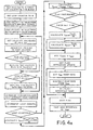
- a presently preferred embodiment of this invention, included in initialization unit 160 of Figure 2, will be described in conjunction with the flow charts of Figure 3.
- the presently preferred embodiment of the present invention is implemented as a programmed microprocessor.
- the presently preferred microprocessor is a Z-80 CPU manufactured by Zilog, Inc., Cupertino, California.
- the program is presented in flow chart form in Figure 3 and is listed in assembly language form in Table 1.
- This program monitors the control signal output of the modulator 110 to determine the appropriate time to initialize the modulator 110 and the reference velocity determination unit 90, and then accomplishes the initialization by introducing a step function modification to the output of the modulator circuit 110 and the reference velocity signal at the appropriate time.
- the presently preferred embodiment of the invention maintains a timer (Timer #2 in Figure 3) which is used to determine when the modulator unit 110 has been commanding substantially no pressure reduction by the antiskid valve for more than a pre-determined time interval.
- the program of Figure 3 is in this embodiment executed about 203 times per second.
- the output signal (PBM) of the modulator 110 is sampled and compared with a threshold value (LOWPBM).
- This threshold value is set equal to a low modulator output which corresponds to substantially no reduction in brake pressure applied to the brake 20, with a small allowance for noise.
- the threshold value is set to correspond to a antiskid valve current of about one milliamp.
- the program branches. If the modulator output is below the threshold, corresponding to a valve current less than 1 milliamp, TIMER #2 is decremented by 1 if it is greater than 1 or left unchanged if it is equal to 1. The minimum value of TIMER #2 is 1, and when TIMER #2 is equal to 1 it indicates that the antiskid valve current commanded by the modulator 110 has been substantially zero for a period greater than the time required for TIMER #2 to time out. An additional timer (TIMER #1) is decremented by 1 in this branch of the program if greater than zero.
- the program enters a second branch in which TIMER #2 is examined to see if it has timed out, indicating that the modulator output is now above the threshold value after an extended period of time below the threshold. If it has, this is taken as an indication that the modulator output and the reference velocity are to be initialized. To accomplish this, the modulator output is set equal to a selected value (PBMSTP) and the reference velocity is set equal to 75% of its previous value. TIMER #2 and TIMER #1 are both then initialized, and TIMER #1 is decremented by 1 if greater than zero.
- PBMSTP selected value
- the initialization value for TIMER #2 is 74 hexadecimal, which equals 116 decimal and corresponds to a timer interval of 0.57 seconds.
- this embodiment operates to initialize both the modulator output and the reference velocity every time the modulator output exceeds the threshold value after remaining below that threshold for 0.57 seconds or more. In operation, this will happen during the initial skid of an aircraft touchdown, and then again whenever a wheel enters a skid after a period of antiskid inactivity.
- the initialization value PBMSTP for the modulator output signal is set at a value appropriate for skid control on a dry runway under normal circumstances. This is particularly true for modulators of the type which act to reduce brake pressure more quickly than to increase brake pressure. In practice, the initialization value is set empirically to minimize stopping distance for the desired conditions.
- the antiskid valve 70 is a single gain valve of the type described in U.S. Patent 4,130,322, for in this case brake pressure is a function of only the control signal on line 61, as long as the metered pressure on line 72 exceeds the pressure commanded by the control signal. When such an antiskid valve 70 is used the initialization value actually corresponds to an initialization brake pressure, assuming the pilot has commanded adequate pressure.
- TIMER #1 which affects the manner in which the reference velocity is determined.
- TIMER #1 is initialized whenever the modulator output and reference velocity are initialized, and TIMER #1 is decremented each time the program of Figure 3 is executed.
- TIMER #1 is initialized to 77 hexadecimal, or 119 decimal. Approximately 0.58 second therefore elapses between the time TIMER #1 is initialized and the time TIMER #1 is next decremented to zero.
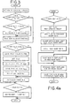
- Figures 4a and 4b provide a flow chart of the operation of the Reference Velocity Determination Unit 90. Tables II and III list the programs of Figures 4a and 4b in assembly language.
- this program first calculates a conditioned velocity signal (V COND ), which is approximately equal to the current average velocity signal from the braked wheel with some allowance for oscillations in the velocity signal.
- V COND conditioned velocity signal
- the conditioned velocity signal is then compared with the reference velocity, which is revised depending on the outcome of the comparison.
- the reference velocity is increased, or updated, by an amount proportional to the difference between the two.
- the proportionality factor is one-thirty-second when TIMER #1 is not equal to zero and one-eighth otherwise.
- the reference velocity is biased towards lower velocities during the initialization period when TIMER #1 is non-zero, because the reference velocity is increased by a smaller fraction of the difference during this period.
- the reference velocity is reduced, or ramped, by a predetermined amount, the ramp rate, which is calculated by the program of Figure 4b.
- the calculation of the ramp rate is dependent on TIMER #1.
- the ramp rate is set to a maximum value, which in this embodiment corresponds to .053 feet per .005 second (1.6 cm. per .005 second).
- the ramp rate is decreased by about 0.0008 feet per second (0.024 cm. per second) each time the reference velocity is greater than the conditioned velocity and the ramp rate is increased by about 0.0001 feet per second (0.003 cm. per second) each time the reference velocity is less than the conditioned velocity.
- TIMER #1 is non-zero for a period of about 0.58 seconds following initialization of the modulator, it is during this period that the-reference velocity is biased towards lower velocities. This results in more aggressive application of brake pressure during the initialization period than at other times. Thus, as the airplane settles on its wheels after the initial touchdown, the antiskid system rapidly adapts to the increased available braking face by aggressively commanding a lesser reduction in brake pressure than at other times.
- Table 1 corresponds to the program of Figure 3
- Table 2a corresponds to the program of Figure 4a
- Table 2b corresponds to the program of Figure 4b
- Table 2c provides a listing of the constants and variables used by the programs of Tables 2a and 2b.
- the wheel speed measurements stored in the velocity block as VELOC1 through VELOC16 are stored as sixteen-bit binary numbers scaled to 0.1 feet per second (3 cm. per second) per LS bit.
- the reference velocity V REF corresponds to the variable REFER which is a twenty-four-bit binary number scaled to about 0.000391 feet per second (0.0117 cm. per second) per bit
- the ramp rate corresponds to RAMP and is scaled identically to REFER.
- the programs of Tables 1, 2a and 2b are each executed after each wheel speed measurement is made, about once every 5 milliseconds in this embodiment.
- Modulator initialization rapidly brings the modulator to a point where it can begin to modulate brake pressure effectively.
- Initialization of the reference signal rapidly brings the reference signal to a point where the antiskid is aggressively controlling the brakes, and biases the reference signal in the direction of aggressive braking for an initial period.
- This embodiment of the invention monitors the output signal of the modulator to determine when to initialize the anti-skid system.
- monitor other signals indicative of excessive braking action For example, the error signal integrated by the modulator, i.e., the difference between the wheel signal and the reference signal, can also be monitored as an indication that a wheel is entering a skid after a period of no skidding and thus that it is appropriate to initialize.
Landscapes
- Engineering & Computer Science (AREA)
- Microelectronics & Electronic Packaging (AREA)
- Physics & Mathematics (AREA)
- Fluid Mechanics (AREA)
- Transportation (AREA)
- Mechanical Engineering (AREA)
- Regulating Braking Force (AREA)
Applications Claiming Priority (2)
| Application Number | Priority Date | Filing Date | Title |
|---|---|---|---|
| US06/132,112 US4338667A (en) | 1980-03-20 | 1980-03-20 | Initialization apparatus for a brake control system |
| US132112 | 1980-03-20 |
Publications (3)
| Publication Number | Publication Date |
|---|---|
| EP0036719A2 true EP0036719A2 (de) | 1981-09-30 |
| EP0036719A3 EP0036719A3 (en) | 1983-02-02 |
| EP0036719B1 EP0036719B1 (de) | 1987-07-22 |
Family
ID=22452534
Family Applications (1)
| Application Number | Title | Priority Date | Filing Date |
|---|---|---|---|
| EP81300948A Expired EP0036719B1 (de) | 1980-03-20 | 1981-03-06 | Inbetriebsetzungsapparat für ein Bremssteuerungssystem |
Country Status (3)
| Country | Link |
|---|---|
| US (1) | US4338667A (de) |
| EP (1) | EP0036719B1 (de) |
| DE (1) | DE3176320D1 (de) |
Cited By (1)
| Publication number | Priority date | Publication date | Assignee | Title |
|---|---|---|---|---|
| EP3225475A1 (de) * | 2016-03-21 | 2017-10-04 | Goodrich Corporation | Adaptive druckschlupfregelung |
Families Citing this family (10)
| Publication number | Priority date | Publication date | Assignee | Title |
|---|---|---|---|---|
| US4530058A (en) * | 1980-03-20 | 1985-07-16 | Crane Co. | Initialization apparatus for a brake control system |
| US4613190A (en) * | 1984-04-10 | 1986-09-23 | Crane Co. | Modulator preset circuit |
| JPS62227842A (ja) * | 1986-03-28 | 1987-10-06 | Honda Motor Co Ltd | 車両速度推定方法 |
| JPH0624912B2 (ja) * | 1987-01-26 | 1994-04-06 | 本田技研工業株式会社 | 車両のアンチロツク制御方法 |
| DE4018495C2 (de) * | 1990-06-09 | 2000-08-03 | Continental Teves Ag & Co Ohg | Schaltungsanordnung zur Verbesserung des Fahrverhaltens eines zur Übersteuerung neigenden Kraftfahrzeuges |
| DE4122016A1 (de) * | 1991-07-03 | 1993-01-21 | Hella Kg Hueck & Co | Antiblockierregelsystem |
| JP2901849B2 (ja) * | 1993-09-07 | 1999-06-07 | 三菱電機株式会社 | アンチスキッド制御装置用フェール検出装置 |
| DE19716291B4 (de) * | 1997-04-18 | 2016-07-07 | Robert Bosch Gmbh | Verfahren und Vorrichtung zum Steuern einer Bremsanlage eines Fahrzeugs |
| US6142585A (en) * | 1997-10-14 | 2000-11-07 | The Boeing Company | Antiskid/autobrake control system with low-speed brake release to reduce gear walk |
| US6241325B1 (en) | 1997-10-14 | 2001-06-05 | The Boeing Company | Low-speed antiskid control for multigain hydraulic valve brake system |
Family Cites Families (6)
| Publication number | Priority date | Publication date | Assignee | Title |
|---|---|---|---|---|
| GB1018548A (en) * | 1964-04-30 | 1966-01-26 | North American Aviation Inc | Automatic wheel brake system |
| US3768873A (en) * | 1971-06-23 | 1973-10-30 | Crane Co | Brake control system |
| US4022513A (en) * | 1972-04-12 | 1977-05-10 | Crane Co., Hydro-Aire Division | Selective deceleration brake control system |
| GB1380744A (en) * | 1972-04-24 | 1975-01-15 | Guntur R R | Vehicle brake control system and a control unit for such a system |
| US4007970A (en) * | 1975-09-30 | 1977-02-15 | The Boeing Company | Aircraft automatic braking system |
| US4180223A (en) * | 1977-12-28 | 1979-12-25 | The Boeing Company | Limited-slip brake control system |
-
1980
- 1980-03-20 US US06/132,112 patent/US4338667A/en not_active Expired - Lifetime
-
1981
- 1981-03-06 DE DE8181300948T patent/DE3176320D1/de not_active Expired
- 1981-03-06 EP EP81300948A patent/EP0036719B1/de not_active Expired
Cited By (2)
| Publication number | Priority date | Publication date | Assignee | Title |
|---|---|---|---|---|
| EP3225475A1 (de) * | 2016-03-21 | 2017-10-04 | Goodrich Corporation | Adaptive druckschlupfregelung |
| US9919795B2 (en) | 2016-03-21 | 2018-03-20 | Goodrich Corporation | Adaptive pressure skid control |
Also Published As
| Publication number | Publication date |
|---|---|
| US4338667A (en) | 1982-07-06 |
| DE3176320D1 (en) | 1987-08-27 |
| EP0036719B1 (de) | 1987-07-22 |
| EP0036719A3 (en) | 1983-02-02 |
Similar Documents
| Publication | Publication Date | Title |
|---|---|---|
| US6527350B2 (en) | System and method for adaptive brake application and initial skid detection | |
| US6916075B2 (en) | System and method for adaptive brake application and initial skid detection | |
| US4338667A (en) | Initialization apparatus for a brake control system | |
| US4530058A (en) | Initialization apparatus for a brake control system | |
| EP0039606B1 (de) | Modulator für Gleitschutz-Bremssystem | |
| EP0039605B1 (de) | Modulator für Gleitschutz-Bremssystem | |
| EP0048309B1 (de) | Einrichtung zur Erzeugung eines Sollwertsignals in einem Bremssteuersystem | |
| EP0247640A2 (de) | Einrichtung zur Erzeugung eines Sollwertsignals in einem Bremssteuersystem |
Legal Events
| Date | Code | Title | Description |
|---|---|---|---|
| PUAI | Public reference made under article 153(3) epc to a published international application that has entered the european phase |
Free format text: ORIGINAL CODE: 0009012 |
|
| AK | Designated contracting states |
Designated state(s): DE FR GB |
|
| PUAL | Search report despatched |
Free format text: ORIGINAL CODE: 0009013 |
|
| AK | Designated contracting states |
Designated state(s): DE FR GB |
|
| 17P | Request for examination filed |
Effective date: 19830627 |
|
| GRAA | (expected) grant |
Free format text: ORIGINAL CODE: 0009210 |
|
| AK | Designated contracting states |
Kind code of ref document: B1 Designated state(s): DE FR GB |
|
| ET | Fr: translation filed | ||
| REF | Corresponds to: |
Ref document number: 3176320 Country of ref document: DE Date of ref document: 19870827 |
|
| PLBE | No opposition filed within time limit |
Free format text: ORIGINAL CODE: 0009261 |
|
| STAA | Information on the status of an ep patent application or granted ep patent |
Free format text: STATUS: NO OPPOSITION FILED WITHIN TIME LIMIT |
|
| 26N | No opposition filed | ||
| PGFP | Annual fee paid to national office [announced via postgrant information from national office to epo] |
Ref country code: FR Payment date: 20000202 Year of fee payment: 20 |
|
| PGFP | Annual fee paid to national office [announced via postgrant information from national office to epo] |
Ref country code: GB Payment date: 20000222 Year of fee payment: 20 Ref country code: DE Payment date: 20000222 Year of fee payment: 20 |
|
| PG25 | Lapsed in a contracting state [announced via postgrant information from national office to epo] |
Ref country code: GB Free format text: LAPSE BECAUSE OF EXPIRATION OF PROTECTION Effective date: 20010305 |
|
| REG | Reference to a national code |
Ref country code: GB Ref legal event code: PE20 Effective date: 20010305 |