EP0036649A1 - Magnetic recording tape - Google Patents
Magnetic recording tape Download PDFInfo
- Publication number
- EP0036649A1 EP0036649A1 EP81102123A EP81102123A EP0036649A1 EP 0036649 A1 EP0036649 A1 EP 0036649A1 EP 81102123 A EP81102123 A EP 81102123A EP 81102123 A EP81102123 A EP 81102123A EP 0036649 A1 EP0036649 A1 EP 0036649A1
- Authority
- EP
- European Patent Office
- Prior art keywords
- magnetic
- magnetic layer
- recording medium
- medium according
- thickness
- Prior art date
- Legal status (The legal status is an assumption and is not a legal conclusion. Google has not performed a legal analysis and makes no representation as to the accuracy of the status listed.)
- Granted
Links
Images

Classifications
-
- G—PHYSICS
- G11—INFORMATION STORAGE
- G11B—INFORMATION STORAGE BASED ON RELATIVE MOVEMENT BETWEEN RECORD CARRIER AND TRANSDUCER
- G11B5/00—Recording by magnetisation or demagnetisation of a record carrier; Reproducing by magnetic means; Record carriers therefor
- G11B5/62—Record carriers characterised by the selection of the material
- G11B5/68—Record carriers characterised by the selection of the material comprising one or more layers of magnetisable material homogeneously mixed with a bonding agent
- G11B5/70—Record carriers characterised by the selection of the material comprising one or more layers of magnetisable material homogeneously mixed with a bonding agent on a base layer
- G11B5/716—Record carriers characterised by the selection of the material comprising one or more layers of magnetisable material homogeneously mixed with a bonding agent on a base layer characterised by two or more magnetic layers
-
- Y—GENERAL TAGGING OF NEW TECHNOLOGICAL DEVELOPMENTS; GENERAL TAGGING OF CROSS-SECTIONAL TECHNOLOGIES SPANNING OVER SEVERAL SECTIONS OF THE IPC; TECHNICAL SUBJECTS COVERED BY FORMER USPC CROSS-REFERENCE ART COLLECTIONS [XRACs] AND DIGESTS
- Y10—TECHNICAL SUBJECTS COVERED BY FORMER USPC
- Y10S—TECHNICAL SUBJECTS COVERED BY FORMER USPC CROSS-REFERENCE ART COLLECTIONS [XRACs] AND DIGESTS
- Y10S428/00—Stock material or miscellaneous articles
- Y10S428/90—Magnetic feature
-
- Y—GENERAL TAGGING OF NEW TECHNOLOGICAL DEVELOPMENTS; GENERAL TAGGING OF CROSS-SECTIONAL TECHNOLOGIES SPANNING OVER SEVERAL SECTIONS OF THE IPC; TECHNICAL SUBJECTS COVERED BY FORMER USPC CROSS-REFERENCE ART COLLECTIONS [XRACs] AND DIGESTS
- Y10—TECHNICAL SUBJECTS COVERED BY FORMER USPC
- Y10S—TECHNICAL SUBJECTS COVERED BY FORMER USPC CROSS-REFERENCE ART COLLECTIONS [XRACs] AND DIGESTS
- Y10S428/00—Stock material or miscellaneous articles
- Y10S428/922—Static electricity metal bleed-off metallic stock
- Y10S428/9265—Special properties
- Y10S428/928—Magnetic property
-
- Y—GENERAL TAGGING OF NEW TECHNOLOGICAL DEVELOPMENTS; GENERAL TAGGING OF CROSS-SECTIONAL TECHNOLOGIES SPANNING OVER SEVERAL SECTIONS OF THE IPC; TECHNICAL SUBJECTS COVERED BY FORMER USPC CROSS-REFERENCE ART COLLECTIONS [XRACs] AND DIGESTS
- Y10—TECHNICAL SUBJECTS COVERED BY FORMER USPC
- Y10T—TECHNICAL SUBJECTS COVERED BY FORMER US CLASSIFICATION
- Y10T428/00—Stock material or miscellaneous articles
- Y10T428/12—All metal or with adjacent metals
- Y10T428/12465—All metal or with adjacent metals having magnetic properties, or preformed fiber orientation coordinate with shape
-
- Y—GENERAL TAGGING OF NEW TECHNOLOGICAL DEVELOPMENTS; GENERAL TAGGING OF CROSS-SECTIONAL TECHNOLOGIES SPANNING OVER SEVERAL SECTIONS OF THE IPC; TECHNICAL SUBJECTS COVERED BY FORMER USPC CROSS-REFERENCE ART COLLECTIONS [XRACs] AND DIGESTS
- Y10—TECHNICAL SUBJECTS COVERED BY FORMER USPC
- Y10T—TECHNICAL SUBJECTS COVERED BY FORMER US CLASSIFICATION
- Y10T428/00—Stock material or miscellaneous articles
- Y10T428/24—Structurally defined web or sheet [e.g., overall dimension, etc.]
- Y10T428/24942—Structurally defined web or sheet [e.g., overall dimension, etc.] including components having same physical characteristic in differing degree
- Y10T428/2495—Thickness [relative or absolute]
- Y10T428/24967—Absolute thicknesses specified
- Y10T428/24975—No layer or component greater than 5 mils thick
-
- Y—GENERAL TAGGING OF NEW TECHNOLOGICAL DEVELOPMENTS; GENERAL TAGGING OF CROSS-SECTIONAL TECHNOLOGIES SPANNING OVER SEVERAL SECTIONS OF THE IPC; TECHNICAL SUBJECTS COVERED BY FORMER USPC CROSS-REFERENCE ART COLLECTIONS [XRACs] AND DIGESTS
- Y10—TECHNICAL SUBJECTS COVERED BY FORMER USPC
- Y10T—TECHNICAL SUBJECTS COVERED BY FORMER US CLASSIFICATION
- Y10T428/00—Stock material or miscellaneous articles
- Y10T428/26—Web or sheet containing structurally defined element or component, the element or component having a specified physical dimension
- Y10T428/263—Coating layer not in excess of 5 mils thick or equivalent
- Y10T428/264—Up to 3 mils
- Y10T428/265—1 mil or less
Definitions
- the present invention relates to improvements over a magnetic recording medium such as a magnetic tape.
- a typical example of the magnetic recording medium is a magnetic tape for recording a musical source and the like, for example, cassette tape.
- a magnetic tape for recording a musical source and the like for example, cassette tape.
- Approaches, which have been proposed to meet such a requirement are Japanese Patent Publication No. 2218/62 and Japanese Patent Disclosure No. 143113/79.
- the magnetic recording medium disclosed in those Gazettes has a dual layered configuration consisting of a low coercive force magnetic layer formed on a base layer and a high coericve force magnetic layer layered on the former layer. With this configuration, a high output level in the short wave range (high frequency range) is attained with little deterioration of MOL (utility maximum output level) in the long wave range (mid bass range).
- MOL utility maximum output level
- the present coating technique can not make the second magnetic layer extremely thin. Under a condition that the thickness of the tape must be fixed over the entire of the tape, the tape base, therefore, must be thinned by the thickness of the second magnetic layer coating. This fact is undesirable for a long play tape of C-120 type of which the thickness must be thinned, from a mechanical strength of view.
- the second magnetic layer made of Co, Fe, Ni or the like
- the second magnetic layer is deposited without binder, that is, the second magnetic layer is deposited on the first magnetic layer by the sputtering or evaporation depositing process, the second magnetic layer may be formed extremely thin.
- a protective layer when practically used must be formed on the second magnetic layer for improving the running performance of the tape, corrosion resistance, wear resistance and the like.
- the protective layer should have a thickness (normally 0.3 to 0.5 ⁇ m) which is thicker than the second magnetic layer, in order to provide a satisfactory function.
- organic macromolecule material is used for the protecting layer, there is produced a disadvantage of spacing loss.
- the second magnetic layer and the gap edge of a magnetic head are separated by the thickness of the protective layer, so that the high frequency range output is more reduced as the protective layer is thicker.
- An experiment shows that, when a sinusoidal wave of 15 KHz is recorded with 2.4 cm/sec of tape speed, the level loss is about 7 dB for 0.2 ⁇ m spacing.
- the thickness of the protective layer is too thick (for example, 0.3 pm or less), the corrosion resistance and the wear resistance are deteriorated and a proximity of the magnetic layer surface to a conductor produces an electrostatic noise and curling or cupping is possibly produced in the layer.
- an object of the present invention is to provide a magnetic recording medium with improved mechanical and magnetic characteristics which is free from deterioration of the corrosion and wear resistances with a minimum of the spacing loss.
- the magnetic recording medium according to the invention comprises a base member or film, a first magnetic layer formed on the film, a secon layer formed on the first magnetic layer, and a third magnetic layer formed on the second layer.
- a thin film containing fine grain alloy such as Fe and Co is used for the second magnetic layer.
- a magnetic layer of fine grain alloy such as y - Fe 2 0 3 including organic binder is used for the thrid magnetic layer.
- the third magnetic layer coated with the organic binder has more excellent mechanical characteristics, for example, the wear resistance than the second magnetic layer.
- the first magnetic layer is the thick film (for example, 1 pm) of relatively low energy such as y - Fe 2 0 3 and the second magnetic layer is an alloy thin film (e.g. 0.3 ⁇ m) of high energy
- the second magnetic layer is coated with the third magnetic layer, the mechanical characteristics such as the wear resistance are excellent.
- the third magnetic layer may be ferromagnetic in substance and properly thin in thickness (for example, 0.5 pm), the spacing loss is small.
- the magnetic recording medium may be thinned over its entire without damaging the advantages.
- the magnitudes of the recording bias and erasing magnetic fields may be kept compatible with those of the conventional recording medium of the iron oxide type. This implies that when the recording medium of the present invention is applied for music tape, the record/playback characteristic can be improved by using the conventional tape recorder as it is. In other words, as long as the recording medium of the present invention is used, there is no need for a tape recorder using a special tape selector position for a metal cassette tape recently prevailed.
- FIG. 1 An example when the magnetic recording medium according to the present invention is applied for a magnetic tape used in a micro- cassette or a compact cassette, is illustrated in Fig. 1.
- a first magnetic layer 12 containing mainly acicular powder of low coercive force type material (about 500 to 600 Oe) such as y - Fe 2 0 3 (gamma hematite) and organic binder is coated over a base film (base) 10 made of polyethylene terephthalate, polyester or the like. Then, the base film 10 coated with the first magnetic layer 12 is subjected to a calendering process.
- base film 10 made of polyethylene terephthalate, polyester or the like.
- metal magnetic material such as Co (cobalt) is obliquely vapor-deposited on the first magnetic layer 12 up to a given thickness at an incident angle of about 60° with respect to a normal of the first magntic layer 12.
- a second magnetic layer 14 is formed on the first magnetic layer 12.
- the coercive force of the second magnetic layer 14 may be 500 to 600 Oe, for example, the formation of the second magnetic layer may be conducted by any other suitable means such as the sputtering.
- a third magnetic layer 16 containing magnetic powder, for example, y - Fe 2 O 3 , together with organic binder is then coated over the second magnetic layer 14.
- the forming method of the magnetic layers 12, 14 and 16 may be a suitable one well known to those skilled in the art.
- the method of forming the layers 12 and 16 is disclosed in "MAGNETIC RECORDING" in Science and Industry, Edited by C.B. Pear, Jr. Reinhold Publishing Corp., New York, pp58 to 84.
- the method of forming the layer 14 may be the one disclosed in Japanese Patent Application No. 176578/80 filed by the applicant of the present patent application or in U.S. Patent No. 3,342,632 (G. Bate et al).
- the thickness tl of the base film 10 is about 7.2 pm; the thickness t2 of the first magnetic layer 12 is about 1.0 pm; the thickness t3 of the second magnetic layer 14 is about 0.3 pm; and the thickness t4 of the third magnetic layer 16 is about 0.5 ⁇ m.
- the above example which is directed for the application of the compact cassette (Philips type) of the C-120, selects the thickness of the base film 10 in accordance with the magnetic layers 12 to 16 so that the total thickness of the tape is always about 9 pm.
- the magnetic tape thus constructed exhibits at the magnetic surface an insulating characteristic like an insulating material to never produce the electrostatic noise.
- An additional advantage of the magnetic tape of the present embodiment is that, since the magnetic energy of the second magnetic layer 14 is large, the total thickness of the magnetic layers 12 to 16, i.e. t2 + t3 + t4, may easily be thinned.
- the third magnetic layer 16 is used for a protection layer for the second magnetic layer 14 and its thickness t4 is selected within a range from about 0.3 ⁇ m to about 1.0 pm.
- the thickness t4 is less than 0.3 pm, unsatisfactory performance of the recording tape is obtained at the present stage in our trial experiment. The reason for this will be described referring to Fig. 2.
- the surface of the second magnetic layer 14 formed on the first magnetic layer 12 by the vapor deposition, the sputtering or the like is considerably rugged when microscopically observed in the order of 0.1 pm. From this, it is concluded that the average thickness t4 ave of the third magnetic layer 16 must be thick enough to cover the surface roughness of the second magnetic layer 14. Otherwise, the third magnetic layer 16 unsatisfactorily functions as the protective layer for the second magnetic layer. Consequently, the average thickness t4 ave , or the given thickness, of the third magnetic layer 16 should be thicker than approximately 0.3 ⁇ m.
- the thickness t4 of the third magnetic layer 16 is too thick (e.g. 1.0 ⁇ m or more), the interval between the second magnetic layer 14 and the gap of a recording head expands, failing to take full advantage of the useful feature of the second magnetic layer 14 which is in high energy and good high frequency range characteristics.
- the total thickness Tt is restricted to the fixed value, if the thickness of the third magnetic layer 16 is made thick, the base film 10 must be thinned to such an extent and therefore a mechanical strength of the tape is deteriorated. Consequently, in the above example, the thickness t4 of the third magnetic layer 16 should be selected to be within approximately 0.3 ⁇ m to 1.0 ⁇ m, preferably 0.3 ⁇ m to 0.5 ⁇ m.
- the thickness of the base film 10 may be selected to be sufficiently thick, as in the case of the cassette tape of the C-90 or C-60 type, the thickness of the magnetic layers 12, 14 and 16 may be selected without severe restriction.
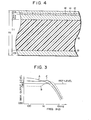
- Fig. 3 is a graph for comparatively illustrating the experimental results of the magnetic tape with the construction shown in Fig. 1 and the prior magnetic tape.
- the tape recorder used was of the 3-head type and tape speed was 2.4 cm/sec.
- a curve A represents a frequency response of the magnetic tape coated with y -Fe 2 0 3 by the binder.
- a curve B represents a frequency response of a three-layered tape which is formed by alternately laying a metal magnetic thin film and a non-magnetic film by the vacuum deposition method.
- the metal thin film tape haivng the response represented by the curve B has a high output level in the high frequency range but its output level is about 7 to 8 dB lower than that of the iron oxide type tape represented by the curve A in the mid range of 100 Hz to 1 KHz.
- the magnetic tape as disclosed in the above-mentioned Gazette of No. 143113/79 has the frequency response corresponding to the combination of the curves A and B and therefore a good MOL over the mid and high frequency ranges.
- a tape of the type in which the magnetic member not using the binder slidably contacts with the magnetic head is poor in the corrosion resistance, the wear resistance and the like when it has no protective layer, however.
- the curve C in Fig. 3 represents a frequency response of the magnetic tape as the embodiment of the present invention shown in Fig. 1.
- the characteristic of the curve C is the well combination of the curve A representing the advantage of the iron oxide type tape, or the high MOL over the low and mid frequency ranges, and the curve B representing the advantage of the metal thin film tape, or the high MOL in the high frequency.
- the magnetic tape of the prior art has still probelms as mentioned above such as wear resistance.
- the magnetic tape, or the magnetic recording medium which is mechanically and chemically stable, having the improved characteristic as shown by the curve C.
- a fourth magnetic layer 18 is formed on the reverse side of the base film 10, that is, the surface opposite to that on which the first to third magnetic layers 12 to 16 are formed.
- the magnetic layer 18 is formed by coating magnetic fine grain alloy of high energy and high permeability, for example, Fe, Co or the like, together with organic binder.
- the thickness t5 of the fourth magnetic layer 18 is selected to be about 1 pm, for example, although it is changeable in accordance with the thickness tl of the base film 10, and the thicknesses t2 to t4 and the coercive force of the first to third magnetic layers.
- the fourth magnetic layer 18 is operable like the back coat of the known back coating type tape and further effectively reduces particularly the transfer effect in the reel take-up type magnetic tape. In other words, even if the recorded magnetic tape with the construction shown in Fig.
- the magnetic layers 12, 16 and 18 in the present invention are formed by the same type coating process using the binder, with the result that the manufacturing process is not so much complicated.
- the materials and the thicknesses of the base film and the magnetic layers are not limited to those described in the above-mentioned embodiments.
- the present invention is applicable for magnetic discs, magnetic cards, magnetic sheets and other proper magnetic recording mediums, in addition to the magnetic tapes.
Landscapes
- Magnetic Record Carriers (AREA)
- Paints Or Removers (AREA)
Abstract
Description
- The present invention relates to improvements over a magnetic recording medium such as a magnetic tape.
- A typical example of the magnetic recording medium is a magnetic tape for recording a musical source and the like, for example, cassette tape. For this type of the magnetic tape, it has been desired that a uniform and large level recording is performed over a wide frequency range. Approaches, which have been proposed to meet such a requirement, are Japanese Patent Publication No. 2218/62 and Japanese Patent Disclosure No. 143113/79. The magnetic recording medium disclosed in those Gazettes has a dual layered configuration consisting of a low coercive force magnetic layer formed on a base layer and a high coericve force magnetic layer layered on the former layer. With this configuration, a high output level in the short wave range (high frequency range) is attained with little deterioration of MOL (utility maximum output level) in the long wave range (mid bass range).
- In coating the surface layer of high coercive force, or the second magnetic layer together with binder, the present coating technique can not make the second magnetic layer extremely thin. Under a condition that the thickness of the tape must be fixed over the entire of the tape, the tape base, therefore, must be thinned by the thickness of the second magnetic layer coating. This fact is undesirable for a long play tape of C-120 type of which the thickness must be thinned, from a mechanical strength of view. When the second magnetic layer (made of Co, Fe, Ni or the like) is deposited without binder, that is, the second magnetic layer is deposited on the first magnetic layer by the sputtering or evaporation depositing process, the second magnetic layer may be formed extremely thin. In this case, however, a protective layer when practically used must be formed on the second magnetic layer for improving the running performance of the tape, corrosion resistance, wear resistance and the like. The protective layer should have a thickness (normally 0.3 to 0.5 µm) which is thicker than the second magnetic layer, in order to provide a satisfactory function. When organic macromolecule material is used for the protecting layer, there is produced a disadvantage of spacing loss. Specifically, the second magnetic layer and the gap edge of a magnetic head are separated by the thickness of the protective layer, so that the high frequency range output is more reduced as the protective layer is thicker. An experiment shows that, when a sinusoidal wave of 15 KHz is recorded with 2.4 cm/sec of tape speed, the level loss is about 7 dB for 0.2 µm spacing. When the thickness of the protective layer is too thick (for example, 0.3 pm or less), the corrosion resistance and the wear resistance are deteriorated and a proximity of the magnetic layer surface to a conductor produces an electrostatic noise and curling or cupping is possibly produced in the layer.
- Accordingly, an object of the present invention is to provide a magnetic recording medium with improved mechanical and magnetic characteristics which is free from deterioration of the corrosion and wear resistances with a minimum of the spacing loss.
- To achieve the above object, the magnetic recording medium according to the invention comprises a base member or film, a first magnetic layer formed on the film, a secon layer formed on the first magnetic layer, and a third magnetic layer formed on the second layer.
- A thin film containing fine grain alloy such as Fe and Co is used for the second magnetic layer. A magnetic layer of fine grain alloy such as y - Fe203 including organic binder is used for the thrid magnetic layer. The third magnetic layer coated with the organic binder has more excellent mechanical characteristics, for example, the wear resistance than the second magnetic layer. When the first magnetic layer is the thick film (for example, 1 pm) of relatively low energy such as y - Fe203 and the second magnetic layer is an alloy thin film (e.g. 0.3 µm) of high energy, satisfactorily large MOL is obtained for both mid bass and high ranges in a well balanced manner. Further, since the second magnetic layer is coated with the third magnetic layer, the mechanical characteristics such as the wear resistance are excellent. Additionally, the third magnetic layer may be ferromagnetic in substance and properly thin in thickness (for example, 0.5 pm), the spacing loss is small.
- Furthermore by properly combining the materials and the thickness of the first to third magnetic layers, the magnetic recording medium may be thinned over its entire without damaging the advantages. In addition the magnitudes of the recording bias and erasing magnetic fields may be kept compatible with those of the conventional recording medium of the iron oxide type. This implies that when the recording medium of the present invention is applied for music tape, the record/playback characteristic can be improved by using the conventional tape recorder as it is. In other words, as long as the recording medium of the present invention is used, there is no need for a tape recorder using a special tape selector position for a metal cassette tape recently prevailed.
- Other objects and advantages of the present invention will be apparent from the following description in connection with the accompanying drawings, in which:
- Fig. 1 is a cross sectional view of a part of an embodiment of a magnetic recording medium according to the present invention;
- Fig. 2 exaggeratively illustrates a cross section of a part of the upper magnetic layers in Fig. 1;
- Fig. 3 is a graphical representation to illustrate how the magnetic characteristic is improved by the magnetic recording medium constructed as shown in Fig. 1; and
- Fig. 4 is a partial cross section of a modification of the magnetic recording medium shown in Fig. 1.
- Before proceeding with the description of the embodiments of the invention, it will expressly be understood that like reference symbols are used to designate like portions throughout the drawings for simplicity of illustration and that the components designated by like reference symbols may easily be replaced with each other or one another with minor change thereof by a skilled person in the art. An embodiment of a magnetic recording medium according to the invention will be described.
- A specific embodiment of a magnetic recording medium according to the invention will be described with reference to the accompanying drawings. An example when the magnetic recording medium according to the present invention is applied for a magnetic tape used in a micro- cassette or a compact cassette, is illustrated in Fig. 1. A first
magnetic layer 12 containing mainly acicular powder of low coercive force type material (about 500 to 600 Oe) such as y - Fe203 (gamma hematite) and organic binder is coated over a base film (base) 10 made of polyethylene terephthalate, polyester or the like. Then, thebase film 10 coated with the firstmagnetic layer 12 is subjected to a calendering process. In the next step metal magnetic material such as Co (cobalt) is obliquely vapor-deposited on the firstmagnetic layer 12 up to a given thickness at an incident angle of about 60° with respect to a normal of the firstmagntic layer 12. As a result of the vapor deposition, a secondmagnetic layer 14 is formed on the firstmagnetic layer 12. The coercive force of the secondmagnetic layer 14 may be 500 to 600 Oe, for example, the formation of the second magnetic layer may be conducted by any other suitable means such as the sputtering. A thirdmagnetic layer 16 containing magnetic powder, for example, y - Fe2O3, together with organic binder is then coated over the secondmagnetic layer 14. Subsequently, the surface of the thirdmagnetic layer 16 is subjected to the calendering process. The forming method of themagnetic layers layers layer 14 may be the one disclosed in Japanese Patent Application No. 176578/80 filed by the applicant of the present patent application or in U.S. Patent No. 3,342,632 (G. Bate et al). - For about 9 µm of the total thickness Tt of the magnetic tape constructed as shown in Fig. 1, the thickness tl of the
base film 10 is about 7.2 pm; the thickness t2 of the firstmagnetic layer 12 is about 1.0 pm; the thickness t3 of the secondmagnetic layer 14 is about 0.3 pm; and the thickness t4 of the thirdmagnetic layer 16 is about 0.5 µm. The above example, which is directed for the application of the compact cassette (Philips type) of the C-120, selects the thickness of thebase film 10 in accordance with themagnetic layers 12 to 16 so that the total thickness of the tape is always about 9 pm. The magnetic tape thus constructed exhibits at the magnetic surface an insulating characteristic like an insulating material to never produce the electrostatic noise. In addition, it is not attendent with the curling or cupping and its tape running characteristic is good. An additional advantage of the magnetic tape of the present embodiment is that, since the magnetic energy of the secondmagnetic layer 14 is large, the total thickness of themagnetic layers 12 to 16, i.e. t2 + t3 + t4, may easily be thinned. - The third
magnetic layer 16 is used for a protection layer for the secondmagnetic layer 14 and its thickness t4 is selected within a range from about 0.3 µm to about 1.0 pm. When the thickness t4 is less than 0.3 pm, unsatisfactory performance of the recording tape is obtained at the present stage in our trial experiment. The reason for this will be described referring to Fig. 2. The surface of the secondmagnetic layer 14 formed on the firstmagnetic layer 12 by the vapor deposition, the sputtering or the like is considerably rugged when microscopically observed in the order of 0.1 pm. From this, it is concluded that the average thickness t4ave of the thirdmagnetic layer 16 must be thick enough to cover the surface roughness of the secondmagnetic layer 14. Otherwise, the thirdmagnetic layer 16 unsatisfactorily functions as the protective layer for the second magnetic layer. Consequently, the average thickness t4ave, or the given thickness, of the thirdmagnetic layer 16 should be thicker than approximately 0.3 µm. - When the thickness t4 of the third
magnetic layer 16 is too thick (e.g. 1.0 µm or more), the interval between the secondmagnetic layer 14 and the gap of a recording head expands, failing to take full advantage of the useful feature of the secondmagnetic layer 14 which is in high energy and good high frequency range characteristics. In case that the total thickness Tt is restricted to the fixed value, if the thickness of the thirdmagnetic layer 16 is made thick, thebase film 10 must be thinned to such an extent and therefore a mechanical strength of the tape is deteriorated. Consequently, in the above example, the thickness t4 of the thirdmagnetic layer 16 should be selected to be within approximately 0.3 µm to 1.0 µm, preferably 0.3 µm to 0.5 µm. In case where the thickness of thebase film 10 may be selected to be sufficiently thick, as in the case of the cassette tape of the C-90 or C-60 type, the thickness of themagnetic layers - Fig. 3 is a graph for comparatively illustrating the experimental results of the magnetic tape with the construction shown in Fig. 1 and the prior magnetic tape. In the measurement of the experiment, the tape recorder used was of the 3-head type and tape speed was 2.4 cm/sec. In Fig. 3, a curve A represents a frequency response of the magnetic tape coated with y -Fe203 by the binder. A curve B represents a frequency response of a three-layered tape which is formed by alternately laying a metal magnetic thin film and a non-magnetic film by the vacuum deposition method. The metal thin film tape haivng the response represented by the curve B has a high output level in the high frequency range but its output level is about 7 to 8 dB lower than that of the iron oxide type tape represented by the curve A in the mid range of 100 Hz to 1 KHz. The magnetic tape as disclosed in the above-mentioned Gazette of No. 143113/79 has the frequency response corresponding to the combination of the curves A and B and therefore a good MOL over the mid and high frequency ranges. As described above, a tape of the type in which the magnetic member not using the binder slidably contacts with the magnetic head is poor in the corrosion resistance, the wear resistance and the like when it has no protective layer, however.
- The curve C in Fig. 3 represents a frequency response of the magnetic tape as the embodiment of the present invention shown in Fig. 1. As shown, the characteristic of the curve C is the well combination of the curve A representing the advantage of the iron oxide type tape, or the high MOL over the low and mid frequency ranges, and the curve B representing the advantage of the metal thin film tape, or the high MOL in the high frequency. When considering only such MOL characteristic, even the magnetic tape disclosed in the Gazette No. 143113/79 may obtain the characteristic as shown by the curve C. The magnetic tape of the prior art, however, has still probelms as mentioned above such as wear resistance. According to the present invention, there is provided the magnetic tape, or the magnetic recording medium, which is mechanically and chemically stable, having the improved characteristic as shown by the curve C.
- Turning now to Fig. 4, there is shown a modification of the embodiment shown in Fig. 1. In the present embodiment, a fourth
magnetic layer 18 is formed on the reverse side of thebase film 10, that is, the surface opposite to that on which the first to thirdmagnetic layers 12 to 16 are formed. Themagnetic layer 18 is formed by coating magnetic fine grain alloy of high energy and high permeability, for example, Fe, Co or the like, together with organic binder. - The thickness t5 of the fourth
magnetic layer 18 is selected to be about 1 pm, for example, although it is changeable in accordance with the thickness tl of thebase film 10, and the thicknesses t2 to t4 and the coercive force of the first to third magnetic layers. The fourthmagnetic layer 18 is operable like the back coat of the known back coating type tape and further effectively reduces particularly the transfer effect in the reel take-up type magnetic tape. In other words, even if the recorded magnetic tape with the construction shown in Fig. 4 is left for a long time, there will not occur an adverse case where the recording magnetic field of the first to third magnetic layers (not shown) right under the fourthmagnetic layer 18 acts on the firstmagnetic layer 12 through thefilm 10 and the recorded contents of the magnetic layer just under it is transferred on the firstmagnetic layer 12 as if it is a ghost signal. - In addition, the
magnetic layers - The embodiments of the invention disclosed and illustrated in the specification and drawings do not limit the present invention and therefore the present invention may be variously changed and modified within the scope and spirit as defined by the appended claims. For example, the materials and the thicknesses of the base film and the magnetic layers are not limited to those described in the above-mentioned embodiments. The present invention is applicable for magnetic discs, magnetic cards, magnetic sheets and other proper magnetic recording mediums, in addition to the magnetic tapes.
Claims (14)
Applications Claiming Priority (2)
| Application Number | Priority Date | Filing Date | Title |
|---|---|---|---|
| JP35815/80 | 1980-03-21 | ||
| JP3581580A JPS56134321A (en) | 1980-03-21 | 1980-03-21 | Magnetic recording medium |
Publications (2)
| Publication Number | Publication Date |
|---|---|
| EP0036649A1 true EP0036649A1 (en) | 1981-09-30 |
| EP0036649B1 EP0036649B1 (en) | 1984-12-12 |
Family
ID=12452421
Family Applications (1)
| Application Number | Title | Priority Date | Filing Date |
|---|---|---|---|
| EP81102123A Expired EP0036649B1 (en) | 1980-03-21 | 1981-03-20 | Magnetic recording tape |
Country Status (5)
| Country | Link |
|---|---|
| US (1) | US4410583A (en) |
| EP (1) | EP0036649B1 (en) |
| JP (1) | JPS56134321A (en) |
| AU (1) | AU525354B2 (en) |
| DE (1) | DE3167675D1 (en) |
Cited By (1)
| Publication number | Priority date | Publication date | Assignee | Title |
|---|---|---|---|---|
| EP0105705A2 (en) * | 1982-10-01 | 1984-04-18 | Hitachi, Ltd. | Perpendicular magnetic recording medium |
Families Citing this family (13)
| Publication number | Priority date | Publication date | Assignee | Title |
|---|---|---|---|---|
| JPS59119532A (en) * | 1982-12-25 | 1984-07-10 | Tdk Corp | Magnetic recording medium |
| JPS59119531A (en) * | 1982-12-25 | 1984-07-10 | Tdk Corp | Magnetic recording medium |
| JPS59119534A (en) * | 1982-12-26 | 1984-07-10 | Tdk Corp | Magnetic recording medium |
| JPS59172142A (en) * | 1983-03-20 | 1984-09-28 | Hitachi Maxell Ltd | Magnetic recording medium |
| US4714641A (en) * | 1983-12-15 | 1987-12-22 | Varian Associates, Inc. | Ferromagnetic films for high density recording and methods of production |
| JP2597967B2 (en) * | 1984-03-09 | 1997-04-09 | 株式会社東芝 | Magnetic recording media |
| JPS60229220A (en) * | 1984-03-09 | 1985-11-14 | Toshiba Corp | Magnetic recording medium |
| US4717592A (en) * | 1984-12-24 | 1988-01-05 | Fuji Photo Film Co., Ltd. | Vertical magnetization type recording medium and manufacturing method therefor |
| JPS61248228A (en) * | 1985-04-26 | 1986-11-05 | Tokyo Jiki Insatsu Kk | Magnetic medium for magnetic embossing and magnetic card using said medium |
| US4861671A (en) * | 1985-10-23 | 1989-08-29 | Kerdix, Inc. | Magneto-optic recording media with protective layer |
| JP2743960B2 (en) * | 1986-02-17 | 1998-04-28 | 日本電信電話株式会社 | Magnetic card |
| US4770924A (en) * | 1986-07-02 | 1988-09-13 | Tdk Corporation | Magnetic recording medium |
| JPH10198950A (en) * | 1996-11-18 | 1998-07-31 | Dainippon Printing Co Ltd | Magnetic card |
Citations (3)
| Publication number | Priority date | Publication date | Assignee | Title |
|---|---|---|---|---|
| DE2461936A1 (en) * | 1974-12-31 | 1976-07-08 | Basf Ag | FLEXIBLE MULTI-LAYER MAGNETOGRAM CARRIER |
| DE2716356A1 (en) * | 1976-04-13 | 1977-10-27 | Fuji Photo Film Co Ltd | Multilayer magnetic recording medium prodn. - using ferromagnetic powder in (co)polyvinylidene chloride, activation and electroless plating |
| US4172171A (en) * | 1976-11-12 | 1979-10-23 | Fuji Photo Film Co., Ltd. | Magnetic recording medium |
Family Cites Families (6)
| Publication number | Priority date | Publication date | Assignee | Title |
|---|---|---|---|---|
| JPS49123005A (en) * | 1973-03-27 | 1974-11-25 | ||
| US4237189A (en) * | 1973-10-31 | 1980-12-02 | Robert J. Deffeyes | Polymodal magnetic recording media process for making and verifying the same and compositions useful therein |
| JPS50104902A (en) * | 1974-01-23 | 1975-08-19 | ||
| JPS5415203B2 (en) * | 1974-01-25 | 1979-06-13 | ||
| JPS5433725B2 (en) * | 1974-07-05 | 1979-10-23 | ||
| US4200678A (en) * | 1974-12-31 | 1980-04-29 | Basf Aktiengesellschaft | Flexible multilayer magnetic recording medium |
-
1980
- 1980-03-21 JP JP3581580A patent/JPS56134321A/en active Pending
-
1981
- 1981-03-17 US US06/244,807 patent/US4410583A/en not_active Expired - Fee Related
- 1981-03-18 AU AU68496/81A patent/AU525354B2/en not_active Ceased
- 1981-03-20 EP EP81102123A patent/EP0036649B1/en not_active Expired
- 1981-03-20 DE DE8181102123T patent/DE3167675D1/en not_active Expired
Patent Citations (3)
| Publication number | Priority date | Publication date | Assignee | Title |
|---|---|---|---|---|
| DE2461936A1 (en) * | 1974-12-31 | 1976-07-08 | Basf Ag | FLEXIBLE MULTI-LAYER MAGNETOGRAM CARRIER |
| DE2716356A1 (en) * | 1976-04-13 | 1977-10-27 | Fuji Photo Film Co Ltd | Multilayer magnetic recording medium prodn. - using ferromagnetic powder in (co)polyvinylidene chloride, activation and electroless plating |
| US4172171A (en) * | 1976-11-12 | 1979-10-23 | Fuji Photo Film Co., Ltd. | Magnetic recording medium |
Cited By (2)
| Publication number | Priority date | Publication date | Assignee | Title |
|---|---|---|---|---|
| EP0105705A2 (en) * | 1982-10-01 | 1984-04-18 | Hitachi, Ltd. | Perpendicular magnetic recording medium |
| EP0105705A3 (en) * | 1982-10-01 | 1986-03-19 | Hitachi, Ltd. | Perpendicular magnetic recording medium |
Also Published As
| Publication number | Publication date |
|---|---|
| EP0036649B1 (en) | 1984-12-12 |
| AU525354B2 (en) | 1982-11-04 |
| JPS56134321A (en) | 1981-10-21 |
| US4410583A (en) | 1983-10-18 |
| DE3167675D1 (en) | 1985-01-24 |
| AU6849681A (en) | 1981-09-24 |
Similar Documents
| Publication | Publication Date | Title |
|---|---|---|
| US4210946A (en) | Magnetic recording medium | |
| US4687712A (en) | Vertical magnetic recording medium | |
| US5224002A (en) | Thin-film magnetic head device | |
| US4371590A (en) | Magnetic recording medium with stepwise orientation of deposited metallic particles | |
| EP0036649B1 (en) | Magnetic recording tape | |
| US5851656A (en) | Magnetic recording medium | |
| US4649073A (en) | Magnetic recording medium | |
| JPH01158618A (en) | Magnetic recording medium | |
| JPS62236131A (en) | Magnetic recording medium and manufacture thereof | |
| US4966821A (en) | Perpendicular magnetic recording medium | |
| KR930009625B1 (en) | Magnetic recording medium | |
| JPH0556565B2 (en) | ||
| US4400444A (en) | Magnetic recording media and process of producing them | |
| JPH0785401A (en) | Magnetic recording method | |
| JPS62128019A (en) | Magnetic recording medium | |
| KR960000822B1 (en) | A magnetic recording medium | |
| JPS60140525A (en) | Magnetic recording medium for vertical recording | |
| JPH0321966B2 (en) | ||
| JPS6134722A (en) | Vertical magnetic recording medium | |
| JPS58171717A (en) | Magnetic recording medium | |
| JPS61187122A (en) | Magnetic recording medium | |
| EP0444571A2 (en) | Magnetic transfer system | |
| Speliotis | Advanced MP++ and BaFe++ tapes | |
| JP2527618B2 (en) | Metal thin film magnetic recording medium | |
| JPH01143312A (en) | Amorphous soft magnetic laminated film |
Legal Events
| Date | Code | Title | Description |
|---|---|---|---|
| PUAI | Public reference made under article 153(3) epc to a published international application that has entered the european phase |
Free format text: ORIGINAL CODE: 0009012 |
|
| AK | Designated contracting states |
Designated state(s): DE FR GB NL |
|
| 17P | Request for examination filed |
Effective date: 19811123 |
|
| GRAA | (expected) grant |
Free format text: ORIGINAL CODE: 0009210 |
|
| AK | Designated contracting states |
Designated state(s): DE FR GB NL |
|
| PG25 | Lapsed in a contracting state [announced via postgrant information from national office to epo] |
Ref country code: NL Effective date: 19841212 Ref country code: FR Free format text: THE PATENT HAS BEEN ANNULLED BY A DECISION OF A NATIONAL AUTHORITY Effective date: 19841212 |
|
| REF | Corresponds to: |
Ref document number: 3167675 Country of ref document: DE Date of ref document: 19850124 |
|
| NLV1 | Nl: lapsed or annulled due to failure to fulfill the requirements of art. 29p and 29m of the patents act | ||
| EN | Fr: translation not filed | ||
| PLBE | No opposition filed within time limit |
Free format text: ORIGINAL CODE: 0009261 |
|
| STAA | Information on the status of an ep patent application or granted ep patent |
Free format text: STATUS: NO OPPOSITION FILED WITHIN TIME LIMIT |
|
| GBPC | Gb: european patent ceased through non-payment of renewal fee | ||
| 26N | No opposition filed | ||
| PG25 | Lapsed in a contracting state [announced via postgrant information from national office to epo] |
Ref country code: DE Effective date: 19861202 |
|
| PG25 | Lapsed in a contracting state [announced via postgrant information from national office to epo] |
Ref country code: GB Effective date: 19881118 |